
Related Manuals for Bosch Optiflow Professional GWH16 1 CTD E23 F5 L


Summary of Contents for Bosch Optiflow Professional GWH16 1 CTD E23 F5 L
- Page 1 Installation Manual Room sealed gas continuous flow water heaters Optiflow Professional GWH12 | 16 | 20 1 CTD E23/31 F5 L 6720808879-00.1V...
-
Page 2: Table Of Contents
Index Index Key to symbols and safety instructions ..3 Regulating the gas Key to symbols ..... . . 3 (only for authorised technicians) . -
Page 3: Key To Symbols And Safety Instructions
Key to symbols and safety instructions – Do not operate any electrical Key to symbols and safety instructions switches or unplug any equipment. Key to symbols – Do not use the telephone or ring doorbells. Warnings ▶ Turn off the gas supply at the main Warnings in this document are identified by a shut-off valve or at the gas meter. - Page 4 • Ensuring the appliance performs to water heater is the responsibility of the specifications stated on the rating the property owner. label. ▶ Use only genuine Bosch spare parts. • Demonstrating the operation of the appliance to the customer before Explosive and highly flammable leaving.
- Page 5 Key to symbols and safety instructions Installation All gas appliances require DANGER: Explosion Risk! adequate air intake to ensure correct combustion. Insects ▶ Always turn off the gas and dirt ingress may affect valve before carrying out combustion causing sooting. any work on components If you notice sooting from the which carry gas.
- Page 6 Key to symbols and safety instructions kPa) MUST be fitted. The preferable prevent hazards from occurring when location for the pressure limiting using electrical appliances: valve is at the water meter. “This appliance can be used by children ▶ Where the pressure limiting valve is of 8 years and older, as well as by people less than 3 metres from the hot water with reduced physical, sensory or...
-
Page 7: Product Details
Product details • Safety devices: Product details – Flame sensor rod – Thermal fuse Declaration of Conformity – Hot water temperature sensor The appliance has been tested and certified to Australia – Electronic control unit Standards. – Air temperature sensor –... -
Page 8: Dimensions And Minimum Clearances
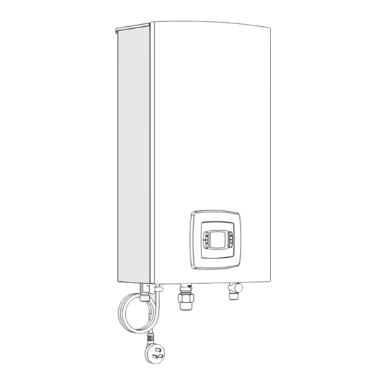
Product details Dimensions and minimum clearances Fig. 1 Dimensions (in mm) Connections Water Cold Nat. Universal GWH12 ½ “ ½ “ ½ “ ½ “ GWH16 GWH20 Table 4 Dimensions (in mm) Optiflow Professional – 6 720 810 560 (2017/11) -
Page 9: Appliance Layout
Product details Appliance layout Fig. 2 [1] Heat exchanger [13] Ignition electrode [2] Flame sensor rod [14] Burner pressure test point [3] Burner [15] Water flow sensor and Water valve [4] Air pressure test point [16] Electronic control unit [5] Fan [17] Cold water temperature sensor [6] Air temperature sensor [18] Gas shut-off valve... -
Page 10: Electrical Wiring Diagram
Product details Electrical wiring diagram Fig. 3 Electrical diagram [1] Flame sensor rod [9] Segmentation electrovalve 2 (gas) [2] Fan [10] Safety electrovalve (gas) [3] Ignition electrode [11] Thermal fuse [4] Power supply [12] Water flow sensor [5] Connection for frost protection [13] Air temperature sensor [6] Connection for remote control [14] Hot water temperature sensor... -
Page 11: Specification
Product details 2.10 Specification Technical features Units GWH12 GWH16 GWH20 Performance Nominal Gas Consumption MJ/h 90.0 120.2 149.0 Minimum gas consumption MJ/h 11.9 18.0 18.0 Efficiency at 100% of nominal load 82.4 82.4 82.4 Gas supply data Gas supply pressure (flowing) Natural gas (when operating) 1.13 1.13... -
Page 12: Flue Accessories
▶ Add any flue lengths, bends, or condensate traps required may cause combustion gases to leak for your configuration. through the appliance installation ▶ Place your order using the Bosch part numbers shown compartment and may result in personal below. injury or death. - Page 13 Product details Type Description Reference Flue Elbow Ø 60/100 90° 7 736 995 079 Flue Elbow Ø 60/100 45° 7 736 995 071 Flue Terminal Extension DN60/100 350mm 7 736 995 059 Flue Terminal Extension DN60/100 750 mm 7 736 995 063 Flue Terminal Extension DN60/100 1500 mm 7 736 995 067 Horizontal Condensate Trap Ø...
-
Page 14: Vertical Installation
Regulations Bosch 4000S flue components Installation (only by an authorised All 4000S coaxial flue components have an internal pipe technicians) diameter of 60 mm and an external pipe diameter of 100 mm. 2.11.2 Vertical installation DANGER: Explosion! Maximum lengths (Lmax) ▶... -
Page 15: Choice Of Installation Site
Installation (only by an authorised technicians) Choice of installation site 4.2.1 Regulations concerning the installation site ▶ The water heater may not be installed over a heat source. ▶ Comply with the minimum installation clearances indicated in fig. 5 and table 10. ▶... -
Page 16: Fitting Hanging-Plate
Installation (only by an authorised technicians) ▶ Remove the appliance from the packaging. Item Min.clea- ▶ Check that all the items indicated are included (section rance (mm) 2.3). D From a gas meter (GM) 1000 ▶ Remove the covers from the gas and water connections. E From an electricity meter or fuse box (P) ▶... -
Page 17: Altitude Of Installation Site
Altitude < 500 m Flue configuration 500 m - 1 000 m Bosch 4000S supplied flue must be used with these appliances. 1 000 m - 1 500 m 1 500 m - 2 000 m Cutting coaxial flue to length... -
Page 18: Electrical Connection (Only By Authorised Technicians)
If the power cable is damaged, it must be The maximum temperature is preset to 55 °C. If required it can replaced with a Bosch supplied spare part. be increased to 60 °C or 70 °C. ▶ Enter the Service function (section 5.2). -
Page 19: Regulating The Gas (Only For Authorised Technicians)
Regulating the gas (only for authorised technicians) ▶ Press the button for 3 seconds. Service function The value flashes to confirm the new setpoint limit. Accessing the service function Calibration example ▶ Press and hold down at the same time ,and for 3 seconds. -
Page 20: Adjusting The Minimum Flow (Parameter P2)
Regulating the gas (only for authorised technicians) ▶ Loosen the test point screw of the air pressure test ▶ Press for 3 seconds. point.[A] The displayed value flashes as a sign of confirmation. ▶ Connect the negative "-" side of the pressure gauge to the ▶... -
Page 21: Factory Default Settings
13. ▶ Press for 3 seconds. ▶ Your appliance should only be attended to by a Bosch The displayed value flashes as a sign of confirmation. service technician. To locate your nearest service provider, ▶ Press to exit this function. -
Page 22: Replacement Of The Fuse
Maintenance (only by authorised service technician) – Fan NOTICE: Damage to the appliance. – Gas valve Damage to the heat exchanger. – Combustion chamber ▶ Do not apply a jet that is too strong or In case of corrosion visible: aimed in a direction other than that ▶... -
Page 23: Troubleshooting
Troubleshooting Troubleshooting Fitting, maintenance and repair must only be carried out by authorised technicians. The following table describes the possible solutions. Display Description Possible solution Cold and hot water temperature sensor damaged. ▶ Check temperature sensor and associated connections. ▶ If the problem persists, call an authorised service technician. - Page 24 Troubleshooting Display Description Possible solution Air temperature sensor detects overheating (leaking ▶ Switch off at the power point and remove combustion products inside the combustion the plug from the electrical socket. chamber). ▶ Do not try to Restart the appliance. ▶...
-
Page 25: Environmental Considerations
Environmental considerations Water quality Environmental protection is a fundamental corporate strategy All Bosch water heating appliances are constructed from high of the Bosch Group. quality materials and components and all are certified for The quality of our products, their efficiency and environmental... -
Page 26: Warranty Details
1. Warranty of the hot water unit. Bosch offers, at its option, to repair or exchange this Bosch hot water unit or the relevant part listed in clause 2 below at no 4. Warranty conditions charge, if it becomes faulty or defective in manufacture or (a) Proof of purchase may be required. - Page 27 Purpose. A customer can object at any time to the use of their personal information for the Purpose. Bosch will cease to use a customer's personal information accordingly if an objection is made.
- Page 28 6720810560...