Table of Contents
Advertisement
Quick Links
Advertisement
Table of Contents

Related Manuals for Bosch B20CS50 Series


Summary of Contents for Bosch B20CS50 Series
-
Page 2: Table Of Contents
C O N T E N T S 1. WARNINGS AND PRECAUTIONS FOR SAFETY -------------------------------------------- 2. EXTERNAL VIEW 2-1. External Size ---------------------------------------------------------------------------------------- 2-2. Name of Each Parts -------------------------------------------------------------------------------- 2-3. Cold Air Circulation -------------------------------------------------------------------------------- 3. SPECIFICATION -------------------------------------------------------------------------------------- 4. OPERATION AND FUNCTIONS ------------------------------------------------------------------- 5. -
Page 3: Warnings And Precautions For Safety
1. WARNINGS AND PRECAUTIONS FOR SAFETY Please observe the following safety precautions in order to use safely and correctly the refrigerator and to prevent accident and danger during repair. 1. Be care of an electric shock. Disconnect power cord from wall outlet and wait for more than three minutes before replacing PCB parts. -
Page 4: External View
2. EXTERNAL VIEWS 2-1. External Size... -
Page 5: Name Of Each Parts
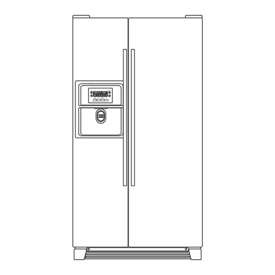
2-2. Name of Each Parts (Model : B20CS50SN* ) Freezer Compartment Refrigerator Compartment 1. Ice cubes storage case 7. Water Filter 2. Freezer light 8. Dairy pocket 3. Water/Ice Dispenser 9. Refrigerator light 4. Freezer shelf 10. Refrigerator shelf 5. Freezer pocket 11. - Page 6 (Model : B20CS80SN*) Freezer Compartment Refrigerator Compartment 1. Ice cubes storage case 7. Water Filter 2. Freezer light 8. Dairy pocket 3. Water/Ice Dispenser 9. Refrigerator light 4. Freezer shelf 10. Shelf wire 5. Freezer pocket 11. Refrigerator shelf 6. Freezer case 12.
-
Page 7: Cold Air Circulation
2-3. Cold Air Circulation Freezer Refrigerator Compartment Compartment... -
Page 8: Specification
3. SPECIFICATION Item Specification Model Name B20CS50SN* B20CS80SN* Total 572Li (20.19 ft 567 Li (20.01 ft Gross Volume Freezer 212 Li (7.48 ft 212 Li (7.48 ft (Li) Refrigerator 360 Li (12.71 ft 355 Li (12.53 ft External Dimension 903mm * 734.5mm *1790mm (Width * Depth * Height) Rated Voltage 115~120V (60Hz) - Page 9 Item Specification Model Name B20CS50SN* B20CS80SN* PBN-43 Defrost Freezer PT-38 Refrigerator PBN-43B Magic Cool Zone PBN-43B Defrost AC115V / 192W Main Duct AC110V / 7W Dispenser Box AC110V / 5W Water Pipe AC110V / 5W Power cord AC125V 15A Fuse Temp (Defrost) AC250V , 10A , 77℃...
-
Page 10: Operation And Functions
4. OPERATION AND FUNCTIONS 4-1. Display INPUT CONTROL OBJECT Front PCB button Freezer Set , Refrigerator Set Super Freeze , Super Cool FCP C-LED Water Filter Reset , Dispenser , Ice Maker Lock ,Lock CONTENTS REMARKS Water filter reset Dispenser select button Ice maker lock button Lock button Super freeze... - Page 11 CONTENTS REMARKS 4. “Refrigerator Set” button. 1) Temperature control of Refrigerator compartment 2) 7 step mode of successive temperature mode. 3) Initial mode by power input : “39℉” ※Whenever pressing button, setting is repeated in the order of (39℉) → (37℉) → (35℉) → (33℉) → (45℉) → (43℉) → (41℉). Letters are indicated on 88 Display LED power Temperature...
- Page 12 4-2. Defrost Mode INPUT CONTROL OBJECT 1. Comp 2. F-Fan 1. Defrosting Cycle 3. R-Fan 4. D-Heater CONTENTS REMARKS 1. Defrost Mode Heater Heater Defrosting Defrosting 1) Comp, F-fan, R-fan : OFF Defrost-Heater : ON 2) Time limit 30 seconds : Heater is ON regardless of D-sensor temperature right after defrosting start 30 minutes : in case of D1- Error 80 minutes : in normal control state...
- Page 13 CONTENTS REMARKS 4. Flow Chart of Defrosting Start Start Comp. operating time is over 2 hours? Total time is over 60 hours? Comp. operating time is over 12 hours? Comp. operating time is over 6 hours? Any error ? Room Temp. ≥...
- Page 14 4-3. Forced Defrosting Mode INPUT CONTROL OBJECT 1. Comp 2. F-Fan 1. Defrosting Cycle 3. R-Fan 4. D-Heater CONTENTS REMARKS 1. A/S Defrosting Mode (Heater defrost → Pause → Fan Delay) Heater Heater Defrosting Defrosting 1) Comp, F-fan, R-fan : OFF D-Heater : ON 2) Time limit 30 seconds : Heater is ON regardless of D-sensor...
- Page 15 4-5. Dispenser and Flap Heater Control INPUT CONTROL OBJECT 1. Comp Dispenser Heater Ice Flap Heater CONTENTS REMARKS It is linked with comp. 4-6. Buzzer or Alarm Control INPUT CONTROL OBJECT 1. Control Front-PCB buttons Buzzer 2. Door Switch 3. Initial Power Input CONTENTS REMARKS 1.
- Page 16 4-8. Demonstration INPUT CONTROL OBJECT Comp 1. “Freezer Set , Dispenser” button F/R-Fan Heater CONTENTS REMARKS 1. Start Push “Dispenser” button 5 times while pushing “Freezer Set” button simultaneously. 2. Control 1) All other electrical components are OFF except for F-Fan / R-Fan 2) Fan Control Door open →...
- Page 17 4-9. Compensation of R-sensor ON/OFF Temp. INPUT CONTROL OBJECT Main PCB Resistance of R-sensor ON/OFF Temp. of Refrigerator CONTENTS REMARKS Compensation of R-sensor ON/OFF temp. (down) In case temperature of refrigerator compartment is weak or insufficient, take the following action. R-SENSOR (31.4㏀) J18,19...
- Page 18 4-10. Error Display INPUT CONTROL OBJECT Temperature Control Buttons 88 Display CLED CONTENTS REMARKS 1. How to start 1) Under “Lock” mode, press “Super Freeze” button 5 times while pressing “Freezer Set” button at the same time. 2) The front C-LED displays as the right diagram shows ( [Ex.] Time Display of 0003 signifies 3 minutes of power on time.) 3) Press “Freezer Set”...
- Page 19 CONTENTS REMARKS 5. Control way of Error (if any) 1) “F1” error Cause : F-sensor disconnection or short Check point : Measure the resistance between both terminals after separating CN8 (or CN15) of the Main PCB. If F-sensor is disconnected or shorted , change the F-sensor in the freezer compartment. How to reset : If F-sensor is normal, the error is terminal temperature.
- Page 20 CONTENTS REMARKS 9) “EI”ERROR Cause : I-SENSOR disconnection / short Check point : Measure the resistance between both terminals after separating CN11 of the Main PCB. If F-sensor is disconnected or shorted , change the I-sensor in the automatic ice maker. 10) “EF”...
- Page 21 4-11. Summary of Function INPUT CONTROL OBJECT Each button CONTENTS REMARKS 1. All the modes are started “Lock” mode (except “Water Filter Reset” mode) 2. Element A/S Function Temp Display change “Water Filter Reset” button for 15 seconds Forced Defrosting “Freezer Set”...
- Page 22 4-12. Filter information & Function to adjust the amount of water INPUT CONTROL OBJECT Temperature Control Buttons 88 Display CLED CONTENTS REMARKS Filter information 1. Filter Exchange Information : Record a real-time from the point of power input. - The filter is normal for 6 months after the first installation. - When the time comes to change or reset, press the Water Filter Reset button for 3 seconds.
- Page 23 4-13. Automatic Icemaker INPUT CONTROL OBJECT Full ice sensing switch Ice Maker Lock Ice separating motor Sensors CONTENTS REMARKS 1. Flow of ice making START Ice making mode Ice is being made ▶ (water supply stand by) Ice separating mode ▶...
- Page 24 CONTENTS REMARKS 2) With the initial power input, Ice tray turns to be horizontal and ice making mode starts. 3) Control of water hose heater * Heater is always ON if RT-sensor has an error or RT is below 15 degree. * Heater is always ON for 60 minutes (max.
- Page 25 CONTENTS REMARKS 3. Ice separating (drop) mode State of Ice tray Ice separating start Horizontal position level S/W 11초 미만 13초 미만 1 sec 0.2 sec normal level S/W motor STOP revolution 12 sec 13 sec 1.1 sec level S/W open error 13 sec 14 sec...
- Page 26 CONTENTS REMARKS 1) Water supply valve is open when water supply mode starts after separation of ices. 2) Water is supplied by time in case sensor has error. 3) Factor valve is variable which can be useful in AS action ①...
- Page 27 CONTENTS REMARKS 4) Control flow & time chart ① Crushed Ice D.P SW D.P Lamp D.P S/V (Flap) Gear Motor ② Cubed Ice D.P SW D.P Lamp Cube S/V D.P S/V (Flap) Gear Motor ③ Water D.P SW (입) D.P Lamp MAIN S/V Water(DIS) S/V Delay time : A = 0.5sec , B =0.
- Page 28 4-15. Compensation of F/R-Compartment temperature. INPUT CONTROL OBJECT Front PCB button ON/OFF Temp. of Freezer Set , Refrigerator Set Freezer & Refrigerator Compartment Super Freeze , Super Cool Dispenser , Lock CONTENTS REMARKS 1. How to start 1) Freezer Compartment : Under “Lock” mode, press “Freeze Set” button 5 times while pressing “Dispenser”...
- Page 29 4-16. Temperature control of “Magic Cool Zone” compartment INPUT CONTROL OBJECT 1. R-Fan 1. “Magic Cool Zone” damper 2. “Magic Cool Zone” sensor 2. Damper heater 3. “SELECT” button CONTENTS REMARKS 1. “Select” button 1) Temperature control of “Magic Cool Zone” compartment 2) 4 step mode of successive temperature mode.
-
Page 30: Wiring Diagram
5. WIRING DIAGRAM... -
Page 31: Component Locate View
6. COMPONENT LOCATE VIEW 6-1. Front View Water Filter Front PCB Dispenser Button Magic Cool Zone Control PCB 6-2. Inner View Freezer Compartment Refrigerator Compartment F-Fan Automatic Motor Geared R-Fan Motor Ice Maker Motor Cover Cover R-Sensor R-Lamp Water Filter F-Door F-Sensor F-Lamp... - Page 32 6-3. Evaporator Water Pipe D-Sensor Evaporator Temp Fuse Defrost Heater 6-4. Machine Compartment Power cord Compressor Condenser Running Dryer Condenser Water Tray Drip Capacitor & PTC Fan-Motor Valve...
-
Page 33: How To Check Each Parts
7. HOW TO CHECK EACH PARTS 7-1. Hose Ice Maker Tube Assembly 1) Disassembling Procedure DISASSEMBLING PROCEDURE DISASSEMBLING PROCEDURE ▷Remove 2 screws at the Cove ▷Pull forward Ice Storage Case Guide Cab W/Tube A. ▷Remove 2 screws. ▷Disassemble Cover Guide Cab W/Tube A ▷Pull forward Ice Maker. -
Page 34: Bracket Geared Motor
7-2. Bracket Geared Motor Assembly 1) Disassembling Procedure DISASSEMBLING PROCEDURE DISASSEMBLING PROCEDURE ▷Remove 2 screws. ▷Pull forward Bracket Geared Motor. Unscrew (red 4 screws). ▷Unscrew (4 points). Unscrew (blue 4 screws). ▷Separate 6 pin housing of Bracket ▷Check Solenoid Valve and Geared Motor. Geared Motor from the top connector. -
Page 35: Dispenser Micro Switch
7-3. Dispenser Micro Switch 1) Disassembling Procedure DISASSEMBLING PROCEDURE DISASSEMBLING PROCEDURE ▷ Insert (-) screw driver into bottom hole of Dispenser Button Guide. ▷Separate wire connectors Pull up forward to remove the guide. from Micro Switch. (Be careful not to damage guide surface.) ▷Check Micro Switch. -
Page 36: Dispenser Solenoid Valve
7-4. Dispenser Solenoid Valve 1) Disassembling Procedure DISASSEMBLING PROCEDURE DISASSEMBLING PROCEDURE ▷ Insert (-) screw driver into bottom left groove of Cover Dispenser Box. Pull forward with a snap.(Be careful not to damage cover and ▷Separate 2 terminals from Sol Valve and door surface.) 2P Housings from Cover Ice Flap. -
Page 37: Main Pcb
7-5. Main PCB ■ Model : FRU-546D,FRU-546E MICOM Item Check Point Remark Compensation for * Used when making R-temp. down J18,19 weak refrigeration to compensate for weak refrigeration →Making R-temp without changing FCP temp. setting. ※Cutting of J18 ⇒ down by 1.5 ℃ cooler ※Cutting of J18, J19 ⇒... -
Page 38: Ice Maker
7-6. Ice Maker ; Disassembling & Check 1) Disassembling procedure Disassembling procedure Disassembling procedure Full ice sensing Level switch switch ▷ Remove 2 screws on top front of ice maker. ▷Remove full ice sensing switch and level switch. ▷ Pull forward ice maker. ▷Unscrew (3 points) Plate Gear Fixture. - Page 39 2) How to check ice maker Parts How to check Criterion ▷ GOOD : RS-360RH-14250 Ice dropping motor : 6 ~ 14Ω ▷ DEFECTIVE : Change the motor. ▷ Check resistance between 2 wires with tester. ▷ GOOD : 4.4 ~ 50kΩ I-Sensor (Ice Sensor) (It depends on ambient temperature)
-
Page 40: Trouble Diagnosis
8. TROUBLE DIAGNOSIS 8-1. Faulty Start (F/R lights OFF , F-PCB Power OFF) Start Power input to Main PCB is ok? Check power connection from machine compartment to CN1 of Main PCB. Main PCB Fuse is disconnected? Change the fuse (AC250V 3.15A) (on the Main PCB) Voltage... -
Page 41: Freezer Compartment
8-2. Freezer Compartment 8-2-1. Freezing failure . (Foods are not frozen / cold.) Start Any error code on Front PCB? Refer to error display in operation and function ※ Refer to the 4-10. (Error Display) Does Comp. work? OLP/PTC is OK? Change the Comp. - Page 42 Removing and replacing Freezer parts 1) Remove foods. 2) Remove Ice bucket, shelves and cases in freezer compartment. * Remove 2 screws * Remove 4 screws of ice maker. of geared motor. * Remove the housing * Remove the housing of ice maker AS.
- Page 43 Removing and replacing Freezer parts (12) * Remove the screw cap on * Remove light cover screws. the F-Louver A with a flat tip driver. (13) * Pull down smoothly the * Remove 3 screws of bottom of light cover to F-Louver A.
- Page 44 Removing and replacing Freezer parts Temp. Fuse Housing 1st : None. 2nd : None. 1st : F-Fan Motor 3rd : Defrost Heater Housing. Housing 2nd : D-Sensor Housing D-Sensor Temp. Fuse Defrost Heater...
- Page 45 8-2-2. Ice Formation on F-Louver Start Dews are formed on the Gasket has a gap Remove the gap. gasket surface inside between cabinet ? F-compartment ? Door is hanged Reassemble the door. down ? Door is open and closed too frequently ? Explain not to open doors too frequently.
- Page 46 8-2-3. Disconnection / breaking of Freezer Lights Wires Start Freezer light filament is disconnected or breaking ? Change the light bulb. Connection of F door switch is OK ? Repair the F-door switch. Check the F door switch connection and F-light socket. Change of F Lights Change of F Door Switch ①...
-
Page 47: Refrigerator Compartment
8-3. Refrigerator Compartment 8-3-1. Refrigeration failure (Foods does not get cool or cold soon.) Start ※ Refer to the 4-10. (Error Display) Any error mode on Front PCB? Solve error code problem, if any. Change R-Fan R-Fan motor the R-Fan motor. works ok ? is ok? Wiring connection... - Page 48 8-3-2. Disconnection / Breaking of Refrigerator Lights Wires Start Freezer light filament is disconnected or breaking ? Change the light bulb. Connection of R door switch is OK ? Repair the R-door switch. Check the R-door switch connection and R-light socket. Change of F Lights Change of F Door Switch ①...
- Page 49 8-3-3. Dews on Refrigerator Compartment Start Dews are formed Gasket has on the gasket inside Repair to eliminate the gap. Any gap ? R-compartment? Door is Reassemble the doors. hanged down ? Door is open too long ? Explain not to open doors too long.
- Page 50 8-3-4. Excessive Refrigeration of Vegetable Case Start Refrigerator temp. mode is “HIGH” ? Explain the temperature modes. Advise to set the temp. to “Normal” or “Warm” mode. R-check valve Works OK ? Repair and/or Change the R-check valve. ※ Refer to “Repair /Change of Check Valve”.
- Page 51 Removing of Check Valve ① * Remove screws ⑤ of light cover. * Remove screws with a (+)screw driver. ② * Hold the bottom of cover and pull ⑥ forward to remove. * Hold the bottom and right of damper to pull down to remove.
-
Page 52: Operation Noise Of Refrigerator
8-4. Operation Noise of Refrigerator 8-4-1. Comp. operation Noise Start Refrigerator is leveled ? Level the refrigerator by adjusting wheels. ☞ Refer to User’s Guide and SVC Manual. Front cover or door gasket is assembled wrong ? Set it right. Rubber absorber comp is distorted or aged ? Change the Rubber absorber. - Page 53 8-4-2. Refrigerant Flow Sound Start Water flowing or hiss sounds from the refrigerator ? Attach an absorber gum on the capillary tube. Refrigerant sound of hiss or sizzling sound when comp. starts ? Apply a gum on the accumulator. Refrigerant sound of hiss or sizzling when comp.
- Page 54 Troubleshooting of Evaporator Sound 1. Hiss Sound from Capillary Tube “I” tube 1) “I” tube is used to connect the capillary tube and evaporator. (2 welding points : ①, ②) 2) When such a sound is made, attach a absorber on the tube including 2 welding points.
- Page 55 8-4-3. Fan Noise Start Fan is damaged or transformed ? Change the fan. Fan is touching the surround ? Set it right not to touch. Fan-motor assembly is moving or shaking ? Set it right not to move. Motor has its own noise or vibration when working ? Change the motor assembly.
- Page 56 Troubleshooting of Fan Noise 1. Fixing or Fastening of Fan Motor 1) Check if fan motor frame of the assembly is fastened tightly with screws to the liner wall. Unless it is tight, vibration of shaking can make. 2) Check if fan motor and fan are hanged down. Fan working sound can be louder if they are not set right.
- Page 57 8-4-4. Pipe Noise Start Pipes are touching in the machine compartment ? Separate the touching pipes, if any. Tray drip makes noise by Condenser shaking ? Apply cushion material between Comp. base and Tray drip. Pipe itself is shaking much ? Move or change the points of vibration absorber rubbers on the pipes to reduce the shaking.
-
Page 58: Door
8-5. Door 8-5-1. Door Opening Alarm Continues though the door is closed. Start Check if interior light is ON. Door switch is pushed well ? Attach a thin pad on the door liner or change the door assembly. Door switch is soaked with water or there is water in the switch ? Change the door switch. -
Page 59: Adjusting F/R Door Balance
8-6. Adjusting F/R Door Balance ※ Top of F/R door is unbalanced horizontally. (Refer to User Guide and SVC Manual for details.) Start Top of F/R is unbalanced within 2 mm ? Refrigerator is level ? Turn the wheels to level refrigerator. Detail Top of F/R is unbalanced within 2 mm ? -
Page 60: Cooling Cycle Heavy Repair
9. COOLING CYCLE HEAVY REPAIR 9-1. Summary of Heavy Repair Process Contents Tools Remove * Cut charging pipe ends (Comp. & Dryer) and refrigerant * Nipper, side cutters discharge refrigerant from drier and compressor. Residuals * Confirm refrigerant (R-134a or R-600a) and oil for compressor and drier. -
Page 61: Precaution During Heavy Repair
9-2. Precautions During Heavy Repair Items Precautions Use of tools. 1) Use special parts and tools for R-134a or R-600a 1) Remove retained refrigerant more than 5 minutes after turning off a refrigerator. (If not, oil will leak inside.) Removal of retained 2) Remove retained refrigerant by cutting first high pressure side refrigerant. -
Page 62: Practical Work For Heavy Repair
9-3. Practical Work for Heavy Repair Items Precautions 1. Removal of residual refrigerant. 1) Remove residual refrigerant more than 5 minutes later after turning off the refrigerator. ( If not, compressor oil may leak inside.) 2) Remove retained refrigerant slowly by cutting first high pressure side (drier part) with a nipper and then cut low pressure side. - Page 63 Items Precautions * Pipe Connection Connect a red hose to the high pressure side and a blue hose 3.Vacuum degassing. to the low pressure side. * Vacuum Sequence Open ①,② valves and evacuate for 40 minutes. Close valve ①. Evaporator Compressor Hot Pipe Condenser...
-
Page 64: Standard Regulations For Heavy Repair
Items Precautions 4.Refrigerant charging. 4) Refrigerant Charging Charge refrigerant while operating a compressor as shown above. 5) Pinch a charging pipe with a pinch-off plier after completion of charging. 6) Braze the end of a pinched charging pipe with copper brazer and take a gas leakage test on the welded parts. -
Page 65: Brazing Reference Drawing
9-5. Brazing Reference Drawings. Accumulator I-Pipe Hot Pipe Suction Pipe Evaporator Pipe Suc Conn Condenser Dryer Pipe Conn B Capi-Tube Compressor ▶ Welding Point ● Copper Welding (Ag 5%) 7 Points ■ Silver Welding (Ag 35%) 3 Points ▶ Flow of Refrigeration Cycle High... -
Page 66: Installation Guide
10. INSTALLATION GUIDE 10-1. Installation Preparation Check if the refrigerator can pass a doorway or enter a door first. Dimensions( including Door Handles) 903mm X 734..5mm X 1790mm (Width*Depth*Height) Find a suitable place to install ※Sufficient space from refrigerator back to the ※Avoid direct sunlight. -
Page 67: If The Refrigerator Can Not Enter The Door
10-2. If the refrigerator can not enter the door ※Remove front bottom cover first, if it is attached. Removing Freezer Door Remove front bottom cover first, Unscrew top hinge cover with a Turn top hinge bolt Pull out the left collar of the screw driver. - Page 68 Replacing Freezer Door Insert the water tube into the hole Insert the bottom hole of freezer Let the top of door close to the Of the bottom hinge pin first, then door straight to the bottom hinge cabinet and insert the top hinge Insert the bottom of freezer door pin.
-
Page 69: Refrigerator Leveling & Door Adjustment
10-3. Refrigerator Leveling & Door Adjustment ※Refrigerator must be level in order to maintain optimal performance and desirable front appearance. (If the floor beneath the refrigerator is uneven, freezer and refrigerator doors look unbalanced.) In case freezer door is lower than refrigerator door Insert a screw driver (flat tip) into a Open the doors, unscrew the front Loosen 3 hinge bolts(1 on the left... -
Page 70: Water Line Installation
10-4. Connect the Tubing to the Refrigerator ※ Before you begin, make sure the refrigerator power cord is not plugged into the wall outlet. and, shut off the main water supply. ※ Water pressure should be 3kgf/cm2 or more to run the automatic icemaker. 1) The compressor compartment access cover must be removed and remove the plastic cap of the water main(1-way) valve. -
Page 71: Dispenser Water Flow
10-5. Dispenser Water Flow BSH Home Appliances Corporation 5551 McFadden Avenue, Huntington Beach, CA 92649 888 522-6724 58300000120605 ARA EN B...