
Related Manuals for Sony XC-ES50L


Summary of Contents for Sony XC-ES50L
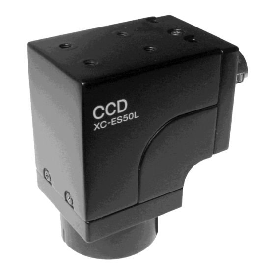
- Page 1 A-BB3-100-11 (1) CCD Black-and-White Video Camera Module Technical Manual XC-ES50L/ES50LCE 2002 Sony Corporation...
-
Page 2: Table Of Contents
When set to Mode 1 ..........13 When set to Mode 2 ..........19 Appendix Specifications ............21 Dimensions .............. 22 XC-ES50L/ES50LCE ..........22 Spectral Sensitivity Characteristics (Typical Value) ............22 XC-ES50L/ES50LCE ..........22 CCD Output Waveform Timing Chart ..... 23 XC-ES50L .............. -
Page 3: Main Features
Overview Overview The XC-ES50L/ES50LCE is a monochrome video Restart/Reset function camera module with a 1/2 type CCD for industrial use. Inputting external HD and VD signals (2 VD or more) Like the XC-ES50/ES50CE, this model provides continuously can catch one image at an arbitrary point various mode switches on the rear panel, making in time and control the stored CCD. -
Page 4: System Components
Overview System Components The XC-ES50L/ES50LCE Video Camera Module system comprises the following components. C C D Video camera module Camera adaptor XC-ES50L/ES50LCE Camera cables DC-700/700CE CCXC-12P02N(2 m) CCXC-12P05N(5 m) CCXC-12P10N(10 m) CCXC-12P25N(25 m) Close-up ring kit C-mount lens LO-77ERK VCL-50Y-M... -
Page 5: Location Of Parts And Operation
Overview Location of Parts and Operation Front/Top/Bottom Reference holes C C D Lens mount (C-mount) 1 Reference holes These precision screw holes are for locking the camera module. 2 Lens mount (C-mount) Attach the VCL-50Y-M C-mount lens or other optical equipment. -
Page 6: Rear Panel
Overview Rear Panel VIDEO OUT/DC IN/SYNC (video output/DC power Shutter speed/Mode setting DIP switch input/sync signal I/O) connector (12-pin) 75Ω termination switch HD/VD signal input/output switch Manual GAIN (M GAIN) control knob 3 HD/VD signal input/output switch Note Set the switch to INT to output HD/VD signals from When you do switch settings, make sure the unit is off. - Page 7 Overview VIDEO OUT/DC IN/SYNC connector pin assignment Rear panel Pin No. Camera sync output External Sync (HD/VD) Restart/Reset External trigger shutter Ground Ground Ground Ground +12 V DC +12 V DC +12 V DC +12 V DC Video output (Ground) Video output (Ground) Video output (Ground) Video output (Ground)
-
Page 8: Specifications Of The Input/Output
Mode Setting Mode Setting Specifications of the Input/Output Input Phase Specifications of Specifications of the Trigger the External HD/VD Pulse 4 to 5.0 V 2 µ sec EVEN, Non Interlace External 0 to 1.0 V 1/4 sec • Input impedance; 10 kΩ or more. External HD 455 (454) 455 (454) -
Page 9: Normal Shutter
Mode Setting Normal Shutter External Trigger Shutter This mode provides continuous video output with the By inputting an external trigger pulse, the camera is electronic shutter selected by switches to capture a able to capture fast-moving objects clearly. high-speed moving object clearly. Set DIP switches 6, 7, and 8 on the rear panel to Mode 1 or Mode 2 (See the table below). - Page 10 Mode Setting Mode 2 (Reset mode) 1/100 (EIA)* 1/125 1/250 1/500 1/120 (CCIR)* 1/10000 (EIA) 1/1000 1/2000 1/4000 1/8000 (CCIR) (Unit: second) * If 1/100 (EIA) or 1/120 (CCIR) has been set, the positions of DIP switches 1 to 3 are optional. Note The positions of DIP switches 5, 9 and 0 are optional.
-
Page 11: Restart/Reset
15.625 kHz (XC-ES50LCE) Allowable frequency value ±1% EXT VD VD interval (T): 262.5 H or more (XC-ES50L) and less than 1 second (Recommended), 312.5 H or more (XC-ES50LCE) and less than 1 second (Recommended) Four or more VD pulses are required. - Page 12 Avoid lighting the scene during the light-emitting inhibit zone defined below. (The field is transferred to the storage area of the CCD, so it can be read out.) Note For best performance, it is recommended that you do not flash between VD and VD + 10 H (XC-ES50L)/16 H (XC-ES50LCE).
-
Page 13: Timing Charts
Mode Setting Timing Charts When set to Mode 1 For setting the shutter speed using the trigger pulse width HD/VD input Continuous VD input Mode transition state External input External trigger inhibition area External trigger shutter operation Normal operation* shutter operation (50 ms) Trigger* Trigger pulse width... - Page 14 Mode Setting For setting the shutter speed using the trigger pulse width HD/VD input Continuous HD input/Single VD input Mode transition state External input External trigger inhibition area External trigger shutter operation Normal operation* shutter operation (50 ms) Trigger* Trigger pulse width Exposure time Exposure time (Te)* (Te)*...
- Page 15 Mode Setting For setting the shutter speed using the trigger pulse width No HD/VD input (Internal synchronization) Mode transition state External input inhibition area External trigger External trigger shutter operation (50 ms) Normal operation* shutter operation Trigger* Trigger pulse width Exposure time Exposure Exposure...
- Page 16 Mode Setting For setting the shutter speed using the DIP switches HD/VD input Continuous VD input Mode transition state External input External trigger Normal inhibition area External trigger shutter operation shutter operation operation* (50 ms) 100 µ s to 250 ms Trigger* Trigger pulse width* Exposure time...
- Page 17 Mode Setting For setting the shutter speed using the DIP switches HD/VD input Continuous HD input/Single VD input Mode transition state External input External trigger inhibition area External trigger shutter operation Normal operation* shutter operation (50 ms) 100 µ s to 250 ms Trigger* Trigger pulse width* Exposure time...
- Page 18 Mode Setting For setting the shutter speed using the DIP switches No HD/VD input (Internal synchronization) Mode transition state External input Normal External trigger inhibition area External trigger shutter operation operation* shutter operation (50 ms) 100 µ s to 250 ms Trigger* Trigger pulse width* Exposure time (Te)*...
-
Page 19: When Set To Mode 2
Mode Setting When set to Mode 2 For setting the shutter speed using the trigger pulse width Mode transition state External input inhibition area External trigger (50 ms) External trigger shutter operation Normal operation* shutter operation Trigger* Trigger pulse width* Exposure time (Te)* Exposure time (Te)*... - Page 20 Mode Setting For setting the shutter speed using the DIP switches Mode transition state External input inhibition area External trigger Normal operation* (50 ms) External trigger shutter operation shutter operation 100 µ s to 250 ms Trigger* Trigger pulse width* Exposure time (Te)* Exposure time (Te)*...
-
Page 21: Specifications
XC-ES50L: 768 (H) × 494 (V) switch on the rear panel) XC-ES50LCE: 752 (H) × 582 (V) Gamma compensation XC-ES50L: 8.4 (H) × 9.8 (V) µm ON/OFF Cell size XC-ES50LCE: 8.6 (H) × 8.3 (V) µm (Can be selected using the XC-ES50L: 7.95 (H) ×... -
Page 22: Dimensions
110 g (4 oz) (Typical Value) Standards UL1492, FCC Class B Digital Device, CE (61326/97+A1/98), AS4251.1+AS4252.1 Other Restart/Reset function XC-ES50L/ES50LCE Frame or field accumulation can be selected. Relative Response New EIAJ compliance 12-pin 1.00 connector pin assignment 0.90 External trigger shutter 0.80... -
Page 23: Ccd Output Waveform Timing Chart
Appendix CCD Output Waveform Timing Chart XC-ES50L Horizontal Output Waveform Timing Chart 91 (6.36 µs) output signal Effective total pixels 768 Dummy Optical black 69.8 ns bits portion Horizontal transfer stop period Optical black portion Horizontal blanking period (11.0 µs) - Page 24 Appendix Vertical Output Waveform Timing Chart (2:1 interlaced frame accumulation) Odd field (262.5 H) Even field (262.5 H) 253.5 H 253.5 H 1 3 5 7 9 2 4 6 8 output signal 242.5 242.5 Empty Empty transfer transfer Camera Optical black portion Optical black portion video...
-
Page 25: Xc-Es50Lce
Appendix XC-ES50LCE Horizontal Output Waveform Timing Chart (6.91 µs) output signal Effective total pixels 752 Dummy Optical black 70.5 ns bits portion Horizontal transfer stop period Optical black portion Horizontal blanking period (12.1 µs) Output video period Camera video output signal (Typical value) 81 (5.71 µs) 736 (51.9 µs) - Page 26 Appendix Vertical Output Waveform Timing Chart (2:1 interlaced frame accumulation) Odd field (312.5 H) Even field (312.5 H) 7.5 H 305 H 7.5 H 305 H 1 3 5 7 9 2 4 6 8 output signal 287.5 287.5 Empty Empty transfer transfer...
- Page 27 Technical information contained herein is for reference only and does not convey any license by any implication or otherwise under any intellectual property right or other right of Sony or third parties. Sony cannot assume responsibility for any right infringements arising out of the use of this information.