
Related Manuals for Toro eHoverPro 450


Summary of Contents for Toro eHoverPro 450
- Page 1 Form No. 3454-974 Rev A eHoverPro™ 450 60V Mower Model No. 02614T—Serial No. 400000000 and Up *3454-974* Register at www.Toro.com. Original Instructions (EN)
-
Page 2: Safety-Alert Symbol
It Model No. is designed to use Toro 60V lithium-ion battery packs. These battery packs are designed to be charged only by Toro 60V lithium-ion battery chargers. Using this Serial No. -
Page 3: Table Of Contents
Replace any damaged or unreadable labels. Use only the battery pack specified by Toro. Using other accessories and attachments may increase the risk of injury and fire. Plugging the battery charger into an outlet... - Page 4 Do not use a battery-operated lawn mower in Charge the battery pack with only the battery rain. charger specified by Toro. A charger suitable for Operate the machine only in good visibility and 1 type of battery pack may create a risk of fire appropriate weather conditions.
- Page 5 Toro distributor perform service on the machine • Replace the battery pack with a genuine using identical replacement parts. Toro battery pack only; using another type of Wear gloves and eye protection when servicing battery pack may cause a fire or risk of injury. the machine.
-
Page 6: Safety And Instructional Decals
Safety and Instructional Decals Safety decals and instructions are easily visible to the operator and are located near any area of potential danger. Replace any decal that is damaged or missing. g017410 H295159 1. Engine stop (shut off) decal111-9826 111–9826 1. - Page 7 decal134-8067 134-8067 1. Warning—read the Operator’s Manual; all operators should 4. Warning—read the Operator’s Manual. be trained before operating the machine. 2. Warning—wear hearing protection and eye protection. 5. Cutting/dismemberment hazard of hands or feet, mower blade—shut off the machine and remove the key before performing maintenance;...
-
Page 8: Setup
Setup Determine the handlebar height when the footstop is secured to the upstop bracket (Figure Align the hole in the footstop with the hole in the lower handlebar (Figure Installing the Handlebar Footstop Parts needed for this procedure: Lower handlebar Footstop Bolt (6 x 35 mm) Washer (6 mm) - Page 9 Installing the Handlebar Parts needed for this procedure: T-bushings Bolt (6 x 55 mm) Washer (6 mm) Locknut (6 mm) Upper handlebar U-bolt Knob Push-in fastener g414364 Figure 6 Pan-head screw Cable clamp 1. Up-stop bracket 2. Footstop Washer Align the hole in the handlebar with the holes in Locknut the bushings (Figure...
- Page 10 g364684 Figure 8 1. Lower handlebar 4. Upper handlebar 2. Knob 5. U-bolt g367353 3. Washer (6 mm) Figure 9 Assemble the upper handlebar to the lower Insert the cable fitting through the hole in the handlebar wit the 2 U-bolts, 2 washer (6 mm), bracket of the operator-presence bail as shown and 2 knobs.
- Page 11 Insert the end of the operator-presence bail into the handlebar, squeeze the other leg of bail slightly, and insert the bail into the handlebar (Figure 11). g367911 Figure 13 1. Pan-head screw 5. Cable clamp 2. Electric-start switch 6. Washer 3.
-
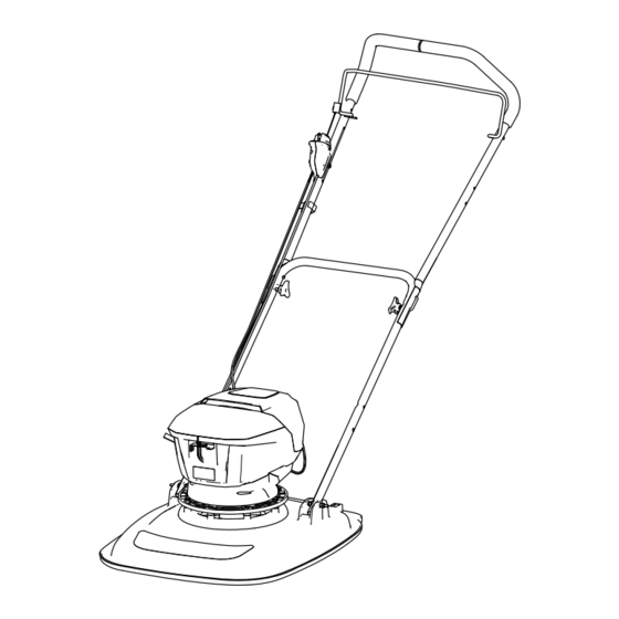
Page 12: Product Overview
Contact your Authorized Service Dealer or authorized Toro distributor or go to www.Toro.com for a list of all Controls approved attachments and accessories. To ensure optimum performance and continued safety... -
Page 13: Before Operation
Operation Before Operation Inserting the Battery Pack into the Machine Important: Use the battery pack only in temperatures that are within the appropriate range; refer Specifications (page 12) Remove the electric-start button from the electric-start switch; refer to Running the Machine (page 14). -
Page 14: During Operation
Shutting Off the Machine During Operation Release the operator presence bail (Figure 17). Running the Machine Insert the electric-start key into the electric-start switch (Figure 16). g367527 Figure 17 Hold the handlebar while you wait for the motor to stop. Remove the electric-start key from the electric-start switch. -
Page 15: Removing The Battery Pack From The Machine
Removing the Battery Pack from the Machine Shut off the machine; refer to Shutting Off the Machine (page 14). Open the battery-compartment cover (Figure 18). Press the battery-pack latch to release the battery pack and remove the battery pack. Close the battery-compartment cover. g414370 Figure 18 Supporting the Handlebar... - Page 16 g364888 Figure 21 g364923 Figure 23 Use a wrench to remove the blade by rotating 1. Impeller 3. Retainer the bolt counterclockwise (Figure 21). 2. Conical spacer 4. Bolt Important: Wear safety glasses and cut-resistant gloves when removing the Torque the blade bolt to 75 N∙m (55 ft-lb). blade.
-
Page 17: Operating Tips
Important: • The battery pack is not fully charged Replace a damaged blade with a new Toro when you purchase it. Before using the tool for replacement blade. the first time, place the battery pack in the charger... - Page 18 To remove the battery pack, pull the battery from the charger. g290533 Figure 26 1. Battery pack cavity 6. Handle 2. Battery pack venting areas 7. Charger LED indicator light 3. Battery pack electrical 8. Charger venting areas contacts 4. Battery-charge-indicator 9.
-
Page 19: Maintenance
• Keep your hands and feet away from a procedure, contact an Authorized Service Dealer moving blade. or authorized Toro distributor. • Wear gloves when servicing the blade. Removing the Blade Checking the Blade Prepare the machine for maintenance;... - Page 20 g364923 Figure 31 1. Impeller 3. Retainer g364990 2. Conical spacer 4. Bolt Figure 29 1. Conical spacer 4. Retainer Torque the blade bolt to 75 N∙m (55 ft-lb). 5. Bolt 2. Spacers Important: A bolt torqued to 75 N∙m (55 ft-lb) 3.
-
Page 21: Cleaning The Machine
Cleaning the Machine Storage Service Interval: Before each use or daily Important: Store the machine, battery pack, and After each use charger only in temperatures that are within the specified range; refer to Charging, Operation, and WARNING Storage Temperature Ranges (page 12). -
Page 22: Troubleshooting
Troubleshooting Perform only the steps described in these instructions. Have an Authorized Service Dealer or authorized Toro distributor complete all further inspection, maintenance, and repair work if you cannot fix the problem. Battery Pack Problem Possible Cause Corrective Action The machine does not start. - Page 23 2. Change the cutting pattern. repeatedly. 3. The underside of the machine housing 3. Clean under the machine housing. contains clippings and debris. 4. There is an electrical problem with the 4. Contact an Authorized Service Dealer machine. or authorized Toro distributor.
- Page 24 While the exposure from Toro products may be negligible or well within the “no significant risk” range, out of an abundance of caution, Toro has elected to provide the Prop 65 warnings. Moreover, if Toro does not provide these warnings, it could be sued by the State of California or by private parties seeking to enforce Prop 65 and subject to substantial penalties.