
Related Manuals for ABB SA-M 16.2.2 Series


Summary of Contents for ABB SA-M 16.2.2 Series
- Page 1 Product manual │ 01.08.2023 ABB-free@home ® SA-M-x.16.2.2 Switch Actuator, 4-, 8-, 12-fold, MDRC Branding -- Release 2018-01-01...
-
Page 2: Table Of Contents
Table of contents Table of contents Notes on the instruction manual ........................3 Safety ................................4 Information and symbols used ......................4 Intended use ............................5 Improper use ............................5 Target group / Qualifications of personnel ..................5 Safety instructions ..........................6 Environment ............................ -
Page 3: Notes On The Instruction Manual
If you pass the device on, also include this manual along with it. ABB accepts no liability for any failure to observe the instructions in this manual. If you require additional information or have questions about the device, please contact ABB or visit our Internet site at: https://new.abb.com/en... -
Page 4: Safety
However, residual hazards remain. Read and adhere to the safety instructions to prevent hazards of this kind. ABB accepts no liability for any failure to observe the safety instructions. Information and symbols used The following Instructions point to particular hazards involved in the use of the device or provide... -
Page 5: Intended Use
Each use not listed in is deemed improper use and can lead to personal injury and damage to property. ABB is not liable for damages caused by use deemed contrary to the intended use of the device. The associated risk is borne exclusively by the user/operator. -
Page 6: Safety Instructions
Safety Safety instructions Danger - Electric voltage! Electric voltage! Risk of death and fire due to electric voltage of 100 … 240 V. Dangerous currents flow through the body when coming into direct or indirect contact with live components. This can result in electric shock, burns or even death. -
Page 7: Environment
Safety Environment Consider the protection of the environment! Used electric and electronic devices must not be disposed of with domestic waste. – The device contains valuable raw materials which can be recycled. Therefore, dispose of the device at the appropriate collecting depot. All packaging materials and devices bear the markings and test seals for proper disposal. -
Page 8: Setup And Function
■ Notice Basic information about system integration is contained in the system manual. It is available for downloading at www.abb.com/freeathome. Scope of supply The scope of supply contains the switch actuator including bus terminal for coupling to the free@home Bus. -
Page 9: Overview Of Types
Setup and function Overview of types Actuator Article no. Product name channels SA-M-4.16.2.2 Switch Actuator, 4-fold, MDRC SA-M-8.16.2.2 Switch Actuator, 8-fold, MDRC Switch Actuator, 12-fold, SA-M-12.16.2.2 MDRC Table 1: Overview of types Product manual 2CKA001473B5406 │9... -
Page 10: Functions
Setup and function Functions 3.3.1 Function overview The following table provides an overview of the possible functions of the device. For a detailed description of functions, see “Actuator parameter function“ on page 32. Icon of the user interface Information Switch actuator Additional heating stage Additional cooling stage Push-button... - Page 11 (configurable in the sensor) of one or several channels (depending on the configuration of the sensors) of the switch actuator and the simultaneous blockage of the switch actuator against the operation of other ABB-free@home ®...
-
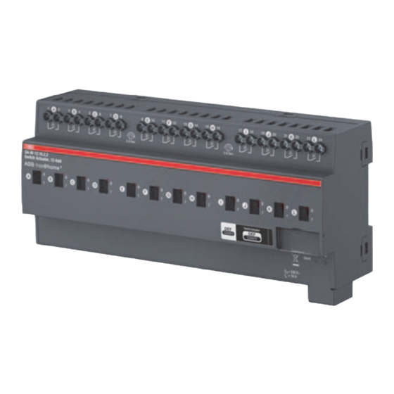
Page 12: Device Overview
Setup and function Device overview SA-M-4.16.2.2 Fig.1: Device overview of switch actuator 4gang MDRC [1] Label holder [2] Identification LED [3] Device identification during commissioning [4] Bus connection terminal [5] Cover cap [6] Load current circuit, per two screw-type terminals [7] Switch-position indicator and manual operation SA-M-8.16.2.2 Fig.2: Device overview of switch actuator 8gang MDRC... - Page 13 Setup and function [2] Identification LED [3] Device identification during commissioning [4] Bus connection terminal [5] Cover cap [6] Load current circuit, per two screw-type terminals [7] Switch-position indicator and manual operation SA-M-12.16.2.2 Fig.3: Device overview of switch actuator 12gang MDRC [1] Label holder [2] Identification LED [3] Device identification during commissioning...
-
Page 14: Technical Data
Technical data Technical data Designation Value Power 21 - 31 VDC Bus subscribers 1 (12 mA) Power loss P [A] SA-M-4.16.2.2 [B] SA-M-8.16.2.2 12 W [C] SA-M-12.16.2.2 Module widths 4 MW (70 mm) [A] SA-M-4.16.2.2 8 MW (140 mm) [B] SA-M-8.16.2.2 12 MW (210 mm) [C] SA-M-12.16.2.2 Bus connection... -
Page 15: Types Of Load
320 A (switching contact) Maximum switch-on current Ip (600 μs) 200 A 18 W (ABB ballasts 1 x 18 SF) 24 W (ABB ballasts-T5 1 x 24 CY) Number of ballasts 36 W (ABB ballasts 1 x 36 CF) (T5/T8, single-light) -
Page 16: Dimensional Drawings
Technical data Dimensional drawings Fig. 4: Dimensions of 4gang switch actuator MDRC (specifications in mm) Fig. 5: Dimensions of 8gang switch actuator MDRC (specifications in mm) Fig. 6: Dimensions of 12gang switch actuator MDRC (specifications in mm) Product manual 2CKA001473B5406 │16... -
Page 17: Connection, Installation / Mounting
Connection, installation / mounting Planning instructions Note Planning and application instructions for the system are available in system ® manual for ABB-free@home . This can be downloaded via www.abb.com/freeathome. Safety instructions Danger - Electric shock due to short-circuit! Risk of death due to electrical voltage of 100 to 240 V during short-circuit in the low-voltage line. -
Page 18: Circuit Diagrams
Connection, installation / mounting Circuit diagrams SA-M-4.16.2.2 Fig. 7: Electrical connection of 4gang switch actuator MDRC SA-M-8.16.2.2 Fig. 8: Electrical connection of 8gang switch actuator MDRC Product manual 2CKA001473B5406 │18... -
Page 19: Mounting / Dismantling
Connection, installation / mounting SA-M-12.16.2.2 Fig. 9: Electrical connection of 12gang switch actuator MDRC Mounting / dismantling The device is a rail mounting device for installing in distributors for easy installation on 35 ■ mm mounting rails according to DIN EN 60 715. The device can be mounted in any position. - Page 20 Connection, installation / mounting Installation To install the device, perform the following steps: – Latch the modular DIN rail component onto the mounting rail. Fig. 10: Installation on mounting rails Dismantling To dismantle the device, perform the following steps: – Press the device down [1] and then fold it toward the front [2].
-
Page 21: Commissioning
Commissioning of the device is carried out via the web-based surface of the System Access ® Point ABB-free@home App Next. It is assumed that the basic commissioning steps of the overall system have already been carried out. Knowledge about the basic functions of the commissioning software of the System Access Point is assumed. - Page 22 Commissioning 6.1.1 Add device Configuring, positioning and linking of the devices is carried out via button "Devices, scenes and groups" (switch icon) in the user interface of the System Access Point. If you do not enter via the main menu, the switch icon may only be visible on the left (see arrow).
- Page 23 Commissioning Fig. 13: Pulling the device out of the menu bar (example illustration) Notice for operation via a mobile phone The building plan/floor plan is not available in the app for mobile phones. – Use the list view of the device configuration here for the location of the device (“Open overview of devices “...
- Page 24 Commissioning The device can be identified via the serial number or via switching. Fig. 14: Allocation of devices A window opens which lists all the devices suitable for the application selected. Identification via serial number Fig. 15: Identification via serial number 5.
- Page 25 Commissioning Identification via switching If several devices are listed in the device list, you can identify them by switching the actual device. Fig. 16: Identification via switching (example illustration) 1. Open the device list. 2. Press the "Identification" button [1] and then switch the actual device. Or, as alternative, press only button [2] in the web interface.
- Page 26 Commissioning Assigning a name Fig. 17: Assigning a name (example illustration) 3. Enter a name that is easy to understand and under which the application is to be displayed later, e.g. "South-wall weather station". 4. Tap the "Save" button to take over the adjustments. –...
-
Page 27: Setting Options Per Channel
Commissioning Setting options per channel General settings and special parameter settings can be made for each channel. The settings are made via the web-based user interface of the System Access Point or the ABB-free@home ® App Next. Select device Fig. 18: Selecting device 1. - Page 28 Commissioning Open overview of devices 1. In the main menu select "Devices, scenes & groups" (toothed-wheel icon) [1]. If you do not enter via the main menu, click on the icon [2]. Fig. 19: Open overview of devices (example illustration) 2.
- Page 29 Commissioning Fig. 20: Overview of devices (example illustration) 3. Tap on a device category. – The list of available devices opens. 4. Tap on the device whose information you want to edit. – A new window with information about the respective device opens. Product manual 2CKA001473B5406 │29...
-
Page 30: Parameters
Commissioning Parameters 6.3.1 Switching Fig. 21: Actuator parameters Under the actuator settings you can configure the settings described in the following. Product manual 2CKA001473B5406 │30... - Page 31 Commissioning Pos. Description Device name An independent designation for the device can be allocated via the text field. Position By tapping on the drop-down menu you can assign a position to the device in the building structure you defined (e.g. assignment to a room on a certain floor). Links Via this function you can also see for which devices a link has been created.
- Page 32 Commissioning Actuator parameter function Heating mode ■ The control is made via the linked room temperature controller which determines a control value between 0 and 100%. The heating actuator converts this control value via PMW. Then the values are rounded < 20 to 0, > 80 to 100, to reduce the number of times the relay is switched.
- Page 33 Commissioning Two-point heating controller ■ The controller switches on when the control value of the room temperature exceeds the preconfigured threshold value and remains active until the heating requirement drops below the preconfigured bottom threshold value again. Two-point cooling controller ■...
-
Page 34: Links
Commissioning Links The weather stations and actuators created via the allocation function can now be linked with each other. This links the individual sensors of the weather station with one or several corresponding actuators. For example, the wind sensor can be linked with blind actuators. This causes the blinds to be moved up when the set wind force is reached. - Page 35 Commissioning 6.4.1 Linking sensor and actuator Configuring, positioning and linking of the devices is carried out via menu "Devices, scenes and groups". Fig. 22: Linking sensor and actuator (example illustration) 1. Select the sensor [1] in the building plan that is to be linked with the actuator (detailed information is available in the system manual).
-
Page 36: Update
Update Update A firmware update is made available via the System Access Point Maintenance The device is maintenance-free. In case of damage, e.g. during transport or storage), do not perform repairs. Once the device is opened, the warranty is void. Access to the device must be guaranteed for operation, testing, inspection, maintenance and repairs (according to DIN VDE 0100-520). -
Page 37: Notes
Notes Notes Product manual 2CKA001473B5406 │37... -
Page 38: Index
Index Index Add device ..........23 Maintenance ..........38 Allocation of devices ........22 Mounting ............. 20 Assigning a name .......... 27 Notes ............39 Circuit diagrams ........... 19 Notes on the instruction manual ......3 Cleaning ............. 38 Commissioning ..........22 Overview of types .......... - Page 39 A member of the ABB Group Notice We reserve the right to make Busch-Jaeger Elektro GmbH technical changes at all times as well P.O. Box as changes to the contents of this 58505 Lüdenscheid document without prior notice. Germany The detailed specifications agreed upon apply for orders.