Table of Contents
Advertisement
Quick Links
Advertisement
Chapters
Table of Contents
Troubleshooting

Related Manuals for LG HB954WA


Summary of Contents for LG HB954WA
- Page 1 Internal Use Only Website http://biz.lgservice.com Blu-ray Wireless Home Theater System SERVICE MANUAL MODEL: HB954WA (HB954WA / SB94WA-C/F/L/R/ W) CAUTION BEFORE SERVICING THE UNIT, READ THE “SAFETY PRECAUTIONS” IN THIS MANUAL. P/NO : AFN70208672 APRIL, 2009...
- Page 2 CONTENTS SECTION 1 ..SUMMARY SECTION 2 ..ELECTRICAL SECTION 3 ..CABINET & MAIN CHASSIS SECTION 4 ..HL-04P LOADER PART SECTION 5 ..REPLACEMENT PARTS LIST...
-
Page 3: Table Of Contents
SECTION 1 SUMMARY CONTENTS PRODUCT SAFETY SERVICING GUIDELINES FOR BLU-RAY DISC PLAYER PRODUCTS ....1-3 SERVICING PRECAUTIONS .......................... 1-4 • GENERAL SERVICING PRECAUTIONS • INSULATION CHECKING PRODEDURE • ELECTROSTATICALLY SENSITIVE (ES) DEVICES SERVICE INFORMATION FOR EEPROM ....................1-5 1. DVD PART 2. -
Page 4: Product Safety Servicing Guidelines For Blu-Ray Disc Player Products
When servicing this product, under no circumstances should the original design be modified or altered without permission from LG Corporation. All components should be replaced only with types identical to those in the original circuit and their physical location, wiring and lead dress must conform to original layout upon completion of repairs. -
Page 5: Servicing Precautions
SERVICING PRECAUTIONS CAUTION: Before servicing the BLU-RAY DISC PLAYER cov- Electrostatically Sensitive (ES) Devices ered by this service data and its supplements and addends, Some semiconductor (solid state) devices can be damaged read and follow the SAFETY PRECAUTIONS. NOTE: if easily by static electricity. -
Page 6: Service Information For Eeprom
SERVICE INFORMATION FOR EEPROM 1. DVD PART POWER ON FLD “NO DISK” or “OPEN” status. DETECT NEW EEPROM (OPTION EDIT SCREEN) EEPROM Edit Table Remote control 41 55 00 AC 00 05 0C 40 Pause key-->1-->4-->7-->2 in order. Up/Down key : Change the EEPROM data Press number 0~9, Press character Left/Righr key : Move the Cursor A~F (1~6 for a while) -
Page 7: Micom Part
2. MICOM PART POWER ON FLD no disc status Remote control ‘2’ + Front ‘STOP’ DETECT NEW EEPROM push same timing during 5s (OPTION EDIT SCREEN) NAME FLD ‘OP-0…. OP-0 OP-1 OP-2 OP-3 OP-4 Use arrow key (◀▲▶▼ ) to move to appropriate position and make changes Press ENTER key once... -
Page 8: Software Upgrade
SOFTWARE UPGRADE 1. Copy D/L program to USB Memory. - file name : Backend program => LG_--.ROM ex) LG_HB_LV421BP.ROM MICOM program => MICOM_--.HEX ex) MICOM_HB954.HEX / MICOM_HB354.HEX TOUCH program => TOUCH_--.HEX ex) TOUCH_HB954.HEX / TOUCH_HB354.HEX DSP program => DSP_--.HEX ex) DSP_HB954.HEX / DSP_HB354.HEX 2. -
Page 9: Specifications
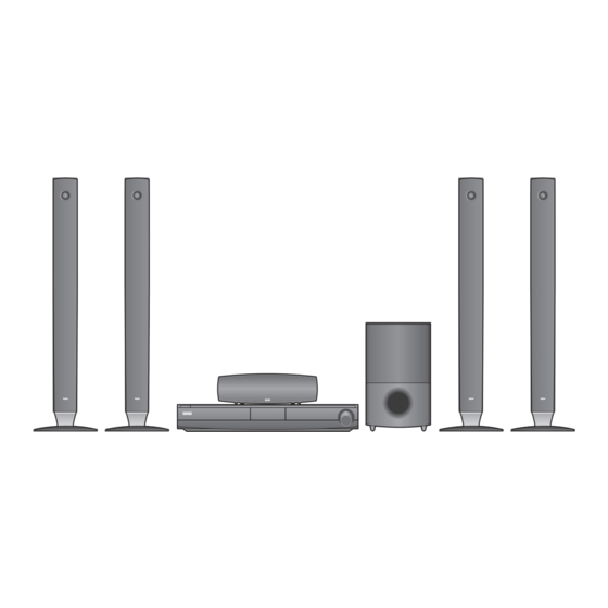
SPECIFICATIONS • GENERAL Power requirements: AC 200 - 240V, 50/60Hz Power consumption: 110W Dimensions (W x H x D): Approx. 430 x 76 x 379mm without foot Net Weight (Approx.): 4.8kg Operating temperature: 41°F to 95°F (5°C to 35°C) Operating humidity: 5% to 90% •... - Page 10 • SPEAKERS Front Rear Speaker Center Passive Speaker (Wireless) Speaker Subwoofer SB94WA-F SB94WA-L/R SB94WA-C SB94WA-W Type 2 Way 3 Speaker 2 Way 3 Speaker 2 Way 3 Speaker 1 Way 1 Speaker Impedance 4Ω 4Ω 4Ω 3Ω Rated Input Power 155W 155W 155W...
- Page 11 MEMO 1-10...
- Page 12 SECTION 2 ELECTRICAL CONTENTS TRAINING MASTER FOR BLU-RAY (BD) ....................2-2 1. DISTORTED PICTURE ........................... 2-2 2. NO PICTURE ............................2-7 3. PICTURE COLOR ..........................2-12 4. NOISE/AUDIO PROBLEMS ........................2-14 5. MISCELLANEOUS ..........................2-17 6. BLU-RAY PLAYER ..........................2-26 7.
-
Page 13: Training Master For Blu-Ray (Bd)
TRAINING MASTER FOR BLU-RAY (BD) Objective: To provide clear and concise guidelines for customer service agents to handle calls on box goods calls. 1. DISTORTED PICTURE 1-1. Lines on Picture Distorted picture refers to the customer getting video, but there is a problem with the video. Determine what cables the customer is using to connect What cables is the BD to the TV and if connected properly. - Page 14 TRAINING MASTER FOR BLU-RAY (BD) 1-2. Ghost Picture Distorted picture refers to the customer getting video, but there is a problem with the video. Determine what cables the customer is using to connect the BD to the TV and if connected properly. Refer to OM for connections. What cables is the customer Tighten any loose cables.
- Page 15 TRAINING MASTER FOR BLU-RAY (BD) 1-3. Rolling Picture Distorted picture refers to the customer getting video, but there is a problem with the video. Determine what cables the customer is using to connect the BD to the TV and if connected properly. Refer to OM for connections. What cables is the customer Tighten any loose cables.
- Page 16 TRAINING MASTER FOR BLU-RAY (BD) 1-4. Shaky Picture Distorted picture refers to the customer getting video, but there is a problem with the video. Determine what cables the customer is using to connect the BD to the TV and if connected properly. Refer to OM for connections. What cables is the customer Tighten any loose cables.
- Page 17 TRAINING MASTER FOR BLU-RAY (BD) 1-5. Blurry Picture Distorted picture refers to the customer getting video, but there is a problem with the video. Determine what cables the customer is using to connect the BD to the TV and if connected properly. Refer to OM for connections. What cables is the customer Tighten any loose cables.
-
Page 18: Picture
TRAINING MASTER FOR BLU-RAY (BD) 2. NO PICTURE 2-1. Black Screen The entire screen is black. Determine what cables the customer is using to connect the BD to the TV and if connected properly. Refer to OM for connections. What cables is the customer Tighten any loose cables. - Page 19 TRAINING MASTER FOR BLU-RAY (BD) 2-2. Blue Screen The entire screen is a solid blue color. Determine what cables the customer is using to connect the BD to the TV and if connected properly. Refer to OM for connections. What cables is the customer Tighten any loose cables.
- Page 20 TRAINING MASTER FOR BLU-RAY (BD) 2-3. Snowy Screen A snowy picture is when black and white dots are all over the screen. Determine what cables the customer is using to connect the BD to the TV and if connected properly. Refer to OM for connections. What cables is the customer Tighten any loose cables.
- Page 21 TRAINING MASTER FOR BLU-RAY (BD) 2-4. No Signal A “no signal” message appears on the screen of the display. Determine what cables the customer is using to connect the BD to the TV and if connected properly. Refer to OM for connections. What cables is the customer Tighten any loose cables.
- Page 22 TRAINING MASTER FOR BLU-RAY (BD) 2-5. Invalid Format or Format Not Supported Make sure the customer’s simultaneously connecting analog component cable with HDMI cable. And then If Copy Protected Disc is playing back, Is the customer using a analog component output is no picture. Only when the analog output digital cable connection? is 576i, you can see the picture.
-
Page 23: Picture Color
TRAINING MASTER FOR BLU-RAY (BD) 3. PICTURE COLOR 3-1. No Color The video displays no color and only shows in black and white. Determine what cables the customer is using to connect the BD What cables is the customer to the TV and if connected properly. Refer to OM for connections. using to connect the BD? Tighten any loose cables. - Page 24 TRAINING MASTER FOR BLU-RAY (BD) 3-2. Poor Color The color is poor. Examples would be washed out colors, colors bleeding into one another, or a solid tint to a screen. Determine what cables the customer is using to connect the BD to What cables is the customer the TV and if connected properly.
-
Page 25: Noise/Audio Problems
TRAINING MASTER FOR BLU-RAY (BD) 4. NOISE/AUDIO PROBLEMS 4-1. No Audio The customer is not able to get audio. Determine what cables the customer is using to connect the BD to the TV and if connected properly. Refer to OM for connections. What cables is the customer Tighten any loose cables. - Page 26 TRAINING MASTER FOR BLU-RAY (BD) 4-2. Distorted Audio The audio sounds muffled, scratchy, or the audio skips. Determine what cables the customer is using to connect the BD to the TV and if connected properly. Refer to OM for connections. What cables is the customer Tighten any loose cables.
- Page 27 TRAINING MASTER FOR BLU-RAY (BD) 4-3. Humming/Clicking Noise The unit is making a humming noise or a clicking noise. BDs make a slight hum when playing discs. Does the noise only A clicking noise or a noise interfering with audio may indicate a problem. happen when a disc Try multiple discs.
-
Page 28: Miscellaneous
TRAINING MASTER FOR BLU-RAY (BD) 5. MISCELLANEOUS 5-1. No Power The unit will not turn on. Is the unit plugged in? Make sure the unit is plugged into a surge protector or the wall. Does the unit turn on See if the unit will turn on when the power button the unit is pressed. when the power button If the unit turns on, then troubleshoot the remote control using is pressed on the unit? - Page 29 TRAINING MASTER FOR BLU-RAY (BD) 5-2. Disc Error The unit displays “disc error” when a disc is inserted into the BD player. Is the disc inserted into Make sure the disc has been inserted into the BD player properly. the BD player properly? The player can not read a disc inserted into the unit upside down.
- Page 30 TRAINING MASTER FOR BLU-RAY (BD) 5-3. Unit Locks Up Unit does not respond to any commands. If the unit will turn on or off with the button on the unit, Does the unit respond to troubleshoot the remote control. Please refer to the buttons on the unit? Remote Control Not Working call flow.
- Page 31 Please refer to the OM for instructions on how to program remote to TV. Customer wants to program a remote Does the customer want to other than Zenith or LG, the customer will need to contact program their remote? the manufacturer of the remote control. Codes do not work, remote is not compatible.
- Page 32 TRAINING MASTER FOR BLU-RAY (BD) 5-6. Will Not Play Disc The unit will not play a disc when a disc is inserted into the player. Is the disc inserted into Make sure the disc has been inserted into the BD player properly. the BD player properly? The player can not read a disc inserted into the unit upside down.
- Page 33 TRAINING MASTER FOR BLU-RAY (BD) 5-7. Disc Freezes or Skips The audio and video freeze and skip during play back of a BD or DVD disc. Is the disc inserted into Make sure the disc has been inserted into the BD player properly. the BD player properly? The player can not read a disc inserted into the unit upside down.
- Page 34 TRAINING MASTER FOR BLU-RAY (BD) 5-8. Can Access Menu, but Not Play a Movie The disc menu is displayed but the disc will not play. Go into the system information screen of the BD player. To access this menu, bring up the main menu. Go to TV aspect, Check the system information highlight 16:9, press 1397139 and hit enter.
- Page 35 TRAINING MASTER FOR BLU-RAY (BD) 5-10. Aspect Ratio The customer has bars on the top and bottom of the screen, the left and right of the screen, or both. A full screen movie played on a wide screen TV will have bars Is the movie on the left and right side of the TV.
- Page 36 TRAINING MASTER FOR BLU-RAY (BD) 5-11. My Unit Won’t Upconvert The customer has a problem with getting the unit to change resolutions to 576p, 720p, 1080i, or 1080p. Ask the customer to press stop to stop the disc from playing. Is the disc Ask the customer to press the resolution button to change the resolution.
-
Page 37: Blu-Ray Player
TRAINING MASTER FOR BLU-RAY (BD) 6. BLU-RAY PLAYER 6-1. Slow Loading Times for BDs The loading times for a blu-ray disc is 30 seconds. Why does it take so When a customer switches from one disc to another, the lens long to load my BDs? will change which is what causes the delay. - Page 38 TRAINING MASTER FOR BLU-RAY (BD) 6-4. Ethernet Port The purpose of the ethernet port on the unit. This is used for the unit to access a network dealing with interactive What is the purpose of BD movie menu. Unit can support BD2.0 so that network the ethernet port on function is active in the BD disc.
-
Page 39: Youtube
TRAINING MASTER FOR BLU-RAY (BD) 7. YouTube 7-1. Network Setup By connecting the unit to broadband Internet, you can use YouTube function Connect the player’s LAN port to the corresponding port Check the Network on your Modem Router using a LAN cable. Connection Use a commercially available straight LAN cable (Category 5/CAT5 or better with RJ45 connector) - Page 40 TRAINING MASTER FOR BLU-RAY (BD) 7-2. Less Bandwidth and less resolution movie than expected The Quality indicator during movie retrieval corresponds to the following bandwidth requirements: • 1 dot is 0.5 Mbps • 2 dots is 1.0 Mbps • 3 dots is 1.6 Mbps •...
-
Page 41: Electrical Troubleshooting Guide
ELECTRICAL TROUBLESHOOTING GUIDE 1. SMPS PART CHECK No power Check the AC Connect the open line line pattern Check the F901 fuse Replace the fuse Low impedance Check a BD901 “+” change IC911, BD901 to “-” pin impedance Check the C968 Check a SMPS second part lines short volt(3.9V) Check a main or AMP assy short... -
Page 42: Amp Protection
ELECTRICAL TROUBLESHOOTING GUIDE 2. AMP PROTECTION “PROTECTION” appears on the FLD. After unplug power cord, connect again. Power on. “PROTECTION” appears continuously on the FLD. Is the IC101 pin27 Replace IC101. “LOW” signal(0V)? Is the Q701, Q702* Replace the Q701, Q702* and Q703. and Q703 normal? Replace TI AMP IC (IC701, IC702, IC703*, IC704*) -
Page 43: Power Key Operation
ELECTRICAL TROUBLESHOOTING GUIDE 3. POWER KEY OPERATION POWER cord insert Stand by LED CN3C1 cable 3p Harness cable connect turn ON? connection OK? CN3C1 pin1 MAIN & SMPS Block check power OK? Replace LED(LD3C1) When you press power key, “WELCOME” FRONT Block check display OK? Power key OK... -
Page 44: Front Block
ELECTRICAL TROUBLESHOOTING GUIDE 4. FRONT BLOCK Power on “WELCOME CN303 cable PLEASE WAIT” Display 20p FFC cable connect connection OK? on VFD OK? After I/F Junction B/D’s power CN303 pin2,3,4,7 line check, SMPS Block check power OK? After I/F Junction B/D’s data CN303 pin10,11,12 data signal OK? line check, MAIN Block check... -
Page 45: Touch Key Block
ELECTRICAL TROUBLESHOOTING GUIDE 5. TOUCH KEY BLOCK Power on CN3A1 Touch key 6EA 5P Harness cable connect connection OK? LED turn on? I/F Junction & Touch Vcc SMPS Block check 3.3V OK? Replace LED check OK? IC3A1 Replace IC3A1 check OK? When you touch keys, LED is blinking? -
Page 46: Audio Check
ELECTRICAL TROUBLESHOOTING GUIDE 6. NO AUDIO CHECK CD/DVD/BD Disc AUX function or USB play IC200’s IC403’s pin4,6, pin9,10 audio IC500 check JK251 check 8,17 I2S signal L/R OK? input OK? IC403’s Micom(IC101) check pin1 LOW? Portable function IC403’s pin3, 12,14,16 I2S signal IC403 check output OK? IC200’s... - Page 47 ELECTRICAL TROUBLESHOOTING GUIDE IPOD function Tuner Function IC200’s Tuner(TUN01) pin11,12 audio check & antenna IPOD B/D IPOD connection or L/R OK? connection check JK3P1’s pin27, 18 audio L/R JK3P1 check IC200’s pin42,43,44 I2S IC201 & X200 check clock OK? I/F Junction 16p FFC cable &...
-
Page 48: Video Check
ELECTRICAL TROUBLESHOOTING GUIDE 7. NO VIDEO CHECK Component video out IC251’s pin1,2,3 IC500 check video signal OK? IC251’s pin6,7,8 IC251 check video signal OK? JK251 check CVBS video out IC250’s pin6 IC500 check video signal OK? IC250’s pin2 IC250’s IC101 check video signal OK? pin1 LOW? IC250 check... - Page 49 ELECTRICAL TROUBLESHOOTING GUIDE CVBS video out (IPOD video) IPOD B/D IPOD connection or JK3P1’s pin23 videio JK3P1 check signal OK? 16p FFC cable & I/F Junction CN3F1’s pin5 OK? connection check 26p FFC cable & MAIN B/D IC254’s pin4 OK? connection check IC250’s pin6 IC254 check...
-
Page 50: Hdmi No Audio/Video Check (With Hdmi In)
ELECTRICAL TROUBLESHOOTING GUIDE 8. HDMI NO AUDIO/VIDEO CHECK (with HDMI IN) HDMI IN function JK803’s pin1,3, JK803 & HDMI cable 4,6,7,9,10,12 TMDS Data connection check signal OK? JK803 JK803 Re-soldering soldering OK? IC807’s pin5,7, IC807 check 8,10,11,13,14,16 TMDS signal OK? IC806’s video IC806 check input signal(pin35~98) - Page 51 ELECTRICAL TROUBLESHOOTING GUIDE Other function JK803’s pin1,3, JK803 & HDMI cable 4,6,7,9,10,12 TMDS Data connection check signal OK? JK803 JK803 Re-soldering soldering OK? IC807’s pin5,7, IC807 check 8,10,11,13,14,16 TMDS signal OK? IC806’s video IC806 check input signal(pin35~98) IC815’s video IC815’s MICOM(IC101) check input signal(pin‘C5’~) pin‘A2’...
-
Page 52: Hdmi No Audio/Video Check (Without Hdmi In)
ELECTRICAL TROUBLESHOOTING GUIDE 9. HDMI NO AUDIO/VIDEO CHECK (without HDMI IN) HDMI OUT JK803’s pin1,3,4,6,7,9,10,12 TMDS JK803 & HDMI cable connection check data signal OK? JK803 JK803 Re-soldering soldering OK IC807’s pin 5,7,8, 10,11,13,14,16 IC807 check TMDS signal OK? IC806’s video input IC806 check signal(pin 35~98) OK? IC500 check... -
Page 53: Waveforms
WAVEFORMS 1. SYSTEM PART-1 X500 27MHz IC500 BCM7440P X501 25MHz 2-42... -
Page 54: System Part-2 (System Memory)
2. SYSTEM PART-2 (SYSTEM MEMORY) IC502 DDR2_0_BA0 IC502 DDR2_0_nWE IC502 DDR2_0_nCAS IC502 DDR2_0_CLK0 2-43... -
Page 55: Video Part-1 (100% Full Color-Bar)
3. VIDEO PART-1 (100% FULL COLOR-BAR) CVBS_I 2-44... -
Page 56: Video Part-2 (100% Full Color-Bar)
4. VIDEO PART-2 (100% FULL COLOR-BAR) CVBS COMP_Y COMP_Pb COMP_Pr 2-45... -
Page 57: Hdmi Part
5. HDMI PART HDMI_SDA HDMI_SCL HDMI_CLK HDMI_DATA 2-46... -
Page 58: Micom And Mpeg I/F Part
6. MICOM AND MPEG I/F PART T_TX R_RX 2-47... - Page 59 MEMO 2-48...
-
Page 60: Wiring Diagram
WIRING DIAGRAM Main PCB AMP PCB CABLE1 (FFC, 22P) CN252 CABLE3 (SATA, 7P) CN253 CN201 CN251 CABLE4 (Harness, 5P) LPB800 LPB801 SMPS PCB Loader(HL-04P) CABLE10 CABLE8 (Harness, 4P) (FFC, 11P) CABLE2 CN901 CABLE7 (Harness, 3P) (FFC, 26P) Wireless option CN3F2 CN3F3 CN301 Front PCB... -
Page 61: Block Diagram
BLOCK DIAGRAM Wireless Option NJM2794 DA788 Wireless 74AHC244 CS8422 5.1ch TX Module i-pod - External Input Decoding - Post Processing 2ch ADC TAS5352 (CS5346) PLIIX / NEO Portable TAS5352 DSP(Room Simul.) 74AHC244 PS9830B VSM , Volume TAS5352 Tuner Music Enhancer Bass Management TAS5352 Audyssey Room EQ... -
Page 62: Circuit Diagrams
DIFFER FROM THE ACTUAL CIRCUIT USED. THIS 2. Voltages are DC-measured with a digital voltmeter 1. SMPS CIRCUIT DIAGRAM PERMISSION FROM THE LG CORPORATION. ALL WAY, IMPLEMENTATION OF THE LATEST SAFETY during Play mode. COMPONENTS SHOULD BE REPLACED ONLY WITH... -
Page 63: Cpu Bcm7440-1 Circuit Diagram
2. CPU BCM7440-1 CIRCUIT DIAGRAM CPU BCM7440-1 HB954/HB354 EBY34069151(#02) REV 7.1 (EAX60805402) 2009. 03. 12 2-55 2-56... -
Page 64: Cpu Bcm7440-2 Circuit Diagram
3. CPU BCM7440-2 CIRCUIT DIAGRAM CPU BCM7440-2 HB954/HB354 EBY34069151(#03) REV 7.1 (EAX60805402) 2009. 03. 12 2-57 2-58... -
Page 65: Ddr Flash, Cp Circuit Diagram
4. DDR FLASH, CP CIRCUIT DIAGRAM DDR,FLASH,CP HB954/HB354 EBY34069151(#04) REV 7.1 (EAX60805402) 2009. 03. 12 2-59 2-60... -
Page 66: Micom Circuit Diagram
5. MICOM CIRCUIT DIAGRAM MICOM HB954/HB354 EBY34069151(#05) REV 7.1 (EAX60805402) 2009. 03. 12 2-61 2-62... -
Page 67: Hdmi Circuit Diagram
6. HDMI CIRCUIT DIAGRAM HDMI HB954/HB354 EBY34069151(#06) REV 7.1 (EAX60805402) 2009. 03. 12 2-63 2-64... -
Page 68: Cpld Circuit Diagram
7. CPLD CIRCUIT DIAGRAM CPLD HB954/HB354 EBY34069151(#07) REV 7.1 (EAX60805402) 2009. 03. 12 2-65 2-66... -
Page 69: Adc/Dir Circuit Diagram
8. ADC/DIR CIRCUIT DIAGRAM ADC/DIR HB954/HB354 EBY34069151(#08) REV 7.1 (EAX60805402) 2009. 03. 12 2-67 2-68... -
Page 70: Dsp Circuit Diagram
9. DSP CIRCUIT DIAGRAM HB954/HB354 EBY34069151(#09) REV 7.1 (EAX60805402) 2009. 03. 12 2-69 2-70... -
Page 71: Power Interface Circuit Diagram
10. POWER INTERFACE CIRCUIT DIAGRAM POWER INTERFACE HB954/HB354 EBY34069151(#10) REV 7.1 (EAX60805402) 2009. 03. 12 2-71 2-72... -
Page 72: Io Interface Circuit Diagram
11. I/O INTERFACE CIRCUIT DIAGRAM I/O INTERFACE HB954/HB354 EBY34069151(#11) REV 7.1 (EAX60805402) 2009. 03. 12 2-73 2-74... -
Page 73: Pwm Circuit Diagram
12. PWM CIRCUIT DIAGRAM 5.1CH OPTION HB954/HB354 EBY34069152(#1) REV 7.1 (EAX60805601) 2009. 01. 20 2-75 2-76... -
Page 74: Amp Circuit Diagram
13. AMP CIRCUIT DIAGRAM 5.1CH OPTION HB954/HB354 EBY34069152(#2) REV 7.1 (EAX60805601) 2009. 01. 20 2-77 2-78... -
Page 75: Front Circuit Diagram
14. FRONT CIRCUIT DIAGRAM FRONT HB954/HB354 EBY34069153 REV 5.1 (EAX60805702) 2009. 03. 12 2-79 2-80... -
Page 76: Power Junction Circuit Diagram
15. POWER JUNCTION CIRCUIT DIAGRAM POWER JUNCTION HB954/HB354 EBY34069150 REV 2.4 (EAX60806002) 2009. 03. 12 2-81 2-82... -
Page 77: Power Key Circuit Diagram
16. POWER KEY CIRCUIT DIAGRAM PWR KEY HB954/HB354 EBY34069158 REV 1.10 (EAX60806102) 2009. 03. 12 2-83 2-84... -
Page 78: Ipod Circuit Diagram
17. IPOD CIRCUIT DIAGRAM IPOD HB954/HB354 EBY34069154 REV 5.4 (EAX60805803) 2009. 03. 12 2-85 2-86... -
Page 79: Touch Circuit Diagram
18. TOUCH CIRCUIT DIAGRAM TOUCH HB954/HB354 EBY60659401 REV 2.3 (EAX60805901) 2009. 01. 20 2-87 2-88... -
Page 80: Circuit Voltage Chart
CIRCUIT VOLTAGE CHART 1. MAIN BOARD Vcc/Vdd Vcc/Vdd Type Type Spec ACTUAL measurement Spec ACTUAL measurement IC101 MICOM IC152 LDO IC LPD78F1164 VDD: 99,100,30 VDD: +2.7~ +4.0V VDD: +3.242 TJ3965 VIN: 2 VIN: ~ +6.5V VIN: +3.805 TYPE: 100P LQFP TYPE: 8P SOP8 VENDER: NEC VENDER: TAEJIN... - Page 81 MEMO 2. AMP BOARD Vcc/Vdd Type Spec ACTUAL measurement IC701, IC702, IC703, IC704 AMP IC TAS5352 VDD: 21 VDD: +10.8 ~ +13.2V VDD: +12.17 TYPE: 44P HTSSOP GVDD: 1,22,23,44 GVDD: +10.8 ~ +13.2V GVDD: +12.10 VENDER: TEXAS INS. PVDD: 40,41,32,26,27 PVDD: ~ +37V PVDD: +34.87 IC709 PWM IC...
-
Page 82: Printed Circuit Board Diagrams
PRINTED CIRCUIT BOARD DIAGRAMS 1. MAIN P.C.BOARD (TOP VIEW) 2-93 2-94... -
Page 83: Main P.c.board
MAIN P.C.BOARD (BOTTOM VIEW) 2-95 2-96... -
Page 84: Smps P.c.board
2. SMPS P.C.BOARD (TOP VIEW) 2-97 2-98... - Page 85 SMPS P.C.BOARD (BOTTOM VIEW) 2-99 2-100...
-
Page 86: Amp P.c.board
3. AMP P.C.BOARD (TOP VIEW) (BOTTOM VIEW) 2-101 2-102... -
Page 87: Front P.c.board
4. FRONT P.C.BOARD (TOP VIEW) (BOTTOM VIEW) 5. IPOD P.C.BOARD (TOP VIEW) (BOTTOM VIEW) 6. TOUCH PAD P.C.BOARD (TOP VIEW) (BOTTOM VIEW) 2-103 2-104... - Page 88 SECTION 3 CABINET & MAIN CHASSIS CONTENTS EXPLODED VIEWS ............................3-3 1. CABINET AND MAIN FRAME SECTION ....................3-3 2. DECK MECHANISM SECTION (HL-04P) ....................3-5 3. PACKING ACCESSORY SECTION ......................3-7 4. SPEAKER SECTION ..........................3-8...
- Page 89 MEMO...
-
Page 90: Exploded Views
EXPLODED VIEWS 1. CABINET AND MAIN FRAME SECTION CABLE3 CABLE8 CABLE4 CABLE7 CABLE9 A43A CABLE6 MAIN CABLE1 CABLE2 WIRELESS TX CABLE10 CN903 CN902 CN901 CABLE5 SMPS A43B A43C... -
Page 91: Deck Mechanism Section (Hl-04P)
2. DECK MECHANISM SECTION (HL-04P) Service Notice 1431 Refer to HOW TO USE THE BAR- CODE SCAN TOOL (Page4-9 ~ 4-11) 1001 after replacing A002, A52 and 1049 1003 1002 A001 A002 1437 1025 1049 1011 1041 1026 1017 1030 1433 1013 1020... -
Page 92: Packing Accessory Section
3. PACKING ACCESSORY SECTION 823 HDMI CABLE 808 BATTERY 824 AM LOOP ANTENNA 811 RCA CABLE VIDEO(1WAY) 825 FM WIRE ANTENNA 900 REMOTE CONTROL 801 OWNER'S MANUAL 804 BAG 803 PACKING, CASING 803 PACKING, CASING 802 BOX SPEAKER CABLE WIRE80 FRONT LEFT 3M WIRE81 FRONT RIGHT 3M WIRE70 CENTER 3M WIRE90 SUBWOOFER 3M... -
Page 93: Speaker Section
4. SPEAKER SECTION 4-1. CENTER SPEAKER (SB94WA-C) A700 754B 754A... - Page 94 4-2. FRONT SPEAKER (SB94WA-F) A800 A800F A800B 853F 853F 858A 858B...
- Page 95 3-10...
- Page 96 4-3. WIRELESS REAR SPEAKER (SB94WA-L/R) A810 : WIRELESS REAR LEFT SPK A820 : WIRELESS REAR RIGHT SPK 856W A800W 853R A48W A800B 850W A45W 858WA A47W SMPS 858WB 300W A800WL : Rx-L ch A800WR : Rx-R ch 3-11...
- Page 97 3-12...
- Page 98 4-4. PASSIVE SUBWOOFER (SB94WA-W) A900 954B 954A 3-13...
- Page 99 3-14...
- Page 100 SECTION 4 HL-04P LOADER PART CONTENTS ELECTRICAL TROUBLESHOOTING GUIDE ..................4-2 1. RESET OR POWER CHECK ........................4-2 2. SYSTEM CHECK ............................4-3 3. TRAY OPERATING IS ABNORMAL ......................4-4 4. SLED OPERATING IS ABNORMAL ......................4-5 5. SPINDLE OPERATING IS ABNORMAL ....................4-6 6.
-
Page 101: Electrical Troubleshooting Guide
ELECTRICAL TROUBLESHOOTING GUIDE 1. RESET OR POWER CHECK Reset or power check. Check it after connecting the power cable only on interface cable for NO Reset or Power ON. Are the Pin1 of Check the power (5V/12V) signal LPB801+5V, Pin4 of LPB801+12V path from SMPS. -
Page 102: System Check
ELECTRICAL TROUBLESHOOTING GUIDE 2. SYSTEM CHECK System Check. Load tray without inserting disc. Does tray Go to “Tray operating is abnormal” operate normally? Does Pick-up move to Go to “Sled operating is abnormal” Inside or outside? Does Pick-up lens move Go to “Focus actuator operating is abnormal”... -
Page 103: Tray Operating Is Abnormal
ELECTRICAL TROUBLESHOOTING GUIDE 3. TRAY OPERATING IS ABNORMAL Tray operating is abnormal Tray open doesn’t work. Is there tray Is there Tray control signal input? control signal output? (LIC201 Pin41) (LIC501 Pin55) Check the connection from LIC501 Pin55. to LIC201 Pin4. •... -
Page 104: Sled Operating Is Abnormal
ELECTRICAL TROUBLESHOOTING GUIDE 4. SLED OPERATING IS ABNORMAL Sled operating is abnormal. Is there sled Replace the LIC501. control signal output? (LIC501 Pin56,57) Is there Check the PCB pattern and components sled drive voltage input? between LIC501 and LIC201 sled signals (LIC201 Pin2,3 ) Is there Check the LIC201. -
Page 105: Spindle Operating Is Abnormal
ELECTRICAL TROUBLESHOOTING GUIDE 5. SPINDLE OPERATING IS ABNORMAL Spindle operating is abnormal Is there spindle control output? Replace the LIC501. (LIC501 Pin58) Is there Is there spindle drive voltage FG signal input? output? (LIC201 Pin12, (LIC501 Pin96) 13,14,16) • Check the output of LIC201 Pin19. •... -
Page 106: Focus Actuator Operating Is Abnormal
ELECTRICAL TROUBLESHOOTING GUIDE 6. FOCUS ACTUATOR OPERATING IS ABNORMAL Focus actuator operating is abnormal. Is there focus • Check the connection of LIC501 Pin54. search control signal input? • Replace the LIC501. (LIC201 Pin40) Is there Check the LIC201 focus search drive voltage output? (LIC201 Pin34,35) Check the signal pattern and application Check the connection... -
Page 107: Laser Operating Is Abnormal
ELECTRICAL TROUBLESHOOTING GUIDE 7. LASER OPERATING IS ABNORMAL Laser operating is abnormal Does Replace the traverse assembly laser turn on? and scan the Pick-up barcode. Check the main PCB Pick-up interface circuit Pin32 : Check the 5V path. Is there Pin33 : Check the 8.1V path LDD vcc voltage input? and LIC902 operation... -
Page 108: How To Use The Bar-Code Scan Tool
HOW TO USE THE BAR-CODE SCAN TOOL Bar-Code Scan Tool inserts the Bar-code values (including Skew, Read power, HFM, LD power and so on) to the Flash-ROM in the Loader Main Board. So, In case of changing the Traverse assembly or Loader main board, It is required to pick-up Bar-code scan procedure. -
Page 109: Running Bar-Code Scan Tool
3. RUNNING BAR-CODE SCAN TOOL When running “LoaderTester.exe” file in the wallpaper(background) of Windows, the following screen appears. Before you start to click “Start” button, remind these. 1) “Test Mode Start” should be selected. 2) Check “only Bar Code” 3) Click “START” Select “Test Mode Start”... -
Page 110: Bar-Code Scan Procedure
4. BAR-CODE SCAN PROCEDURE 1) Untie the screw of Loader. 2) Connect the “USB to SATA connector” and “SATA Power” to the Loader. 3) Connect the “USB to SATA connector” to the PC. 4) Connect the “Bar-Code Scanner” to the PC. 5) Run the Bar-Code Scan Tool (Loader Tester). -
Page 111: Internal Structure Of The Pick-Up
INTERNAL STRUCTURE OF THE PICK-UP 1. OPTICAL LAYOUT 2- OBL type 650/780nm LD 405nm LD DVD/CD Layout Blu-ray Layout 4-12... -
Page 112: Sf-Bd411 Pdic Composition
2. SF-BD411 PDIC COMPOSITION Vref SA SD RF+,RF-(BD) RF+,RF- (DVD/CD) 4-13... -
Page 113: Pick-Up Connector Terminal Pin Assignments
3. PICK-UP CONNECTOR TERMINAL PIN ASSIGNMENTS PIN NO PIN NAME DESCRIPTION FCS2+ FOCUSING2+ FCS2- FOCUSING2- TRK+ TRACKING+ FCS1+ FOCUSING1+ TRK- TRACKING- FCS1- FOCUSING1- Stepping Motor A- Terminal Stepping Motor B- Terminal Stepping Motor A+ Terminal Stepping Motor B+ Terminal CL SHIFTER VCC_CLSFT Sensor Power Supply 3.3V SIG_PO... -
Page 114: Major Ic Internal Block Diagram And Pin Description
MAJOR IC INTERNAL BLOCK DIAGRAM AND PIN DESCRIPTION 1. LIC501 (MT8575) : Blu-ray SIGNAL PROCESSOR SINGLE CHIP 1-1. Pin Assignment 4-15... - Page 115 1-2. Block Diagram 4-16...
- Page 116 1-3. Pin Function PIN NO PIN NAME TYPE DESCRIPTION RF Signals & S/H Control Pulses (21) TRINA Analog Input Input of Tracking Signal (A) TRINB Analog Input Input of Tracking Signal (B) TRINC Analog Input Input of Tracking Signal (C) TRIND Analog Input Input of Tracking Signal (D)
- Page 117 PIN NO PIN NAME TYPE DESCRIPTION AVDD12_3 Analog Power(1.2V) Power Pin AVDD12_4 Analog Power(1.2V) Power Pin AVDD33_4 Analog Power(3.3V) Power Pin AVDD12_1 Analog Power(1.2V) Power Pin AVDD33_1 Analog Power(3.3V) Power Pin Low-Speed General Output (10) LGO1P Analog Output Lowspeed General Output 1P LGO1N Analog Output Lowspeed General Output 1N...
- Page 118 PIN NO PIN NAME TYPE DESCRIPTION LDD serial interface (3) 3.3V LVTTL I/O, LDD_SDIO LDD serial interface data. The pin is spike-free at power-on stage. 5V-tolerance, LDD_CLK LDD serial interface CLK. The pin is spike-free at power-on stage. 2,4,6,8mA PDR, LDD serial interface command enable.
-
Page 119: Lic201 (R2A30232Sp) : Spindle Motor And 6Ch Actuator Driver
2. LIC201 (R2A30232SP) : SPINDLE MOTOR AND 6CH ACTUATOR DRIVER 2-1. Block Diagram 4-20... - Page 120 2-2. Pin Function PIN NO SYMBOL FUNCTION SPIN Spindle control voltage input SL1IN Slide control voltage input 1 SL2IN Slide control voltage input ÇQ SPLIM Input terminal for spindle current limit Motor Power Supply ÇQ(for Slide) SL2+ Slide non-inverted output 2 SL2- Slide inverted output 2 SL1+...
- Page 121 MEMO 4-22...
-
Page 122: Circuit Diagram
CIRCUIT DIAGRAM LOADER (HL-04P) EBY51750301 REV. 6.1 2009. 01. 20 4-23 4-24... -
Page 123: Circuit Voltage Chart
CIRCUIT VOLTAGE CHART PIN NO. VOLTAGE PIN NO. VOLTAGE PIN NO. VOLTAGE PIN NO. VOLTAGE LIC100 LIC501 3.30 1.34 3.30 0.00 1.41 1.34 3.30 PULSE 1.01 1.35 3.30 3.30 2.10 2.57 3.30 0.00 0.00 1.33 3.30 0.00 1.05 1.33 1.19 0.00 1.15 1.33... -
Page 124: Printed Circuit Board Diagrams
PRINTED CIRCUIT BOARD DIAGRAMS (TOP VIEW) 4-27 4-28... - Page 125 (BOTTOM VIEW) 4-29 4-30...