
Related Manuals for ABB TMAX XT XT2 ELECTRONIC


Summary of Contents for ABB TMAX XT XT2 ELECTRONIC
- Page 1 — INSTRUCTION HANDBOOK 1SDH002293A1001 - ECN000285442 TMAX XT XT2 ELECTRONIC Disassembly instructions...
-
Page 3: Safety Notes
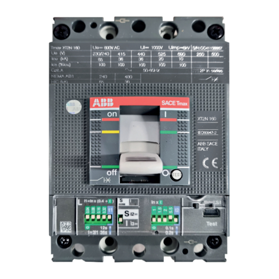
Disassembly instruction tmaX Xt Xt2 electronic 1. SCOPE Scope of this document is to illustrate the step-by-step disassembly process of ABB SACE Tmax XT XT2 moulded case circuit breaker equipped with an electronic trip unit (type Ekip DIP). Document is focused on Tmax XT XT2 3p IEC version, anyway it allows to cover other versions of Tmax XT XT2 circuit breaker equipped with an electronic trip unit with just few slight differences to be taken into account. -
Page 4: Disassembly Process
INSTRUCTION HANDBOOK 5. SEPARATE TREATMENT Table below lists parts requiring a separate treatment adding information about part location inside circuit breakers and related quantity. Description Position inside circuit breaker Quantity Cap kits In correspondence of circuit breaker connection terminals Cases for microswitches In the right hole of the circuit breaker Plug In the left hole of the circuit breaker... - Page 5 Disassembly instruction tmaX Xt Xt2 electronic 6.1 PHASE 1 – CAP KITS Tools Actions to be performed Allen key Insert the flat screwdriver as shown in the By means of the allen key remove the screws picture and push it up in order to remove the connected with the cap kits.
- Page 6 INSTRUCTION HANDBOOK 6.2 PHASE 2 – BREAKING PART FRONTAL Actions to be performed Tools Cross screwdriver By means of the cross screwdriver unscrew the By means of the cross screwdriver push the 2 screws fixing the braking part frontal to the trip test button.
- Page 7 Disassembly instruction tmaX Xt Xt2 electronic 6.3 PHASE 3 – TOGGLE AND ITS PROTECTION Actions to be performed Tools – Manually lift the toggle and its protection and after separate the toggle from its protection. Disassembled parts • 1 toggle (Plastic) • 1 toggle protection (Plastic)
- Page 8 INSTRUCTION HANDBOOK 6.4 PHASE 4 – TRIP UNIT Actions to be performed Tools Cross screwdriver By means of the cross screwdriver unscrew the Manually disassemble the transparent 2 screws fixing the trip unit frontal to the trip protection from the trip unit frontal. unit main structure.
- Page 9 Disassembly instruction tmaX Xt Xt2 electronic Manually slightly pull the trip unit as indicated by the arrow and after lift the trip unit in order to complete the removal. Disassembled parts • 2 screws (Metal) • 1 trip unit frontal (Plastic) • 1 trip unit transparent protection (Plastic) • 1 label (Adhesive paper) • 1 trip unit (Plastic, Metal, Electronic components, …) *...
- Page 10 INSTRUCTION HANDBOOK 6.5 PHASE 5 – PLASTIC PARTS MOUNTED ON THE BREAKING PART Actions to be performed Tools Flat screwdriver Manually slightly push the 2 flaps present on By means of the flat screwdriver lift the plug each case for microswitch located in the right located in the left hole of the breaking part and hole of the breaking part as indicated by the after manually complete the removal of the...
- Page 11 Disassembly instruction tmaX Xt Xt2 electronic 6.6 PHASE 6 – REAR COVER Actions to be performed Tools Cross screwdriver By means of the cross screwdriver unscrew the Manually remove the rear cover 2 screws fixing the rear cover to the breaking part.
- Page 12 INSTRUCTION HANDBOOK 6.7 PHASE 7 – OPERATING MECHANISM AND TRIPPING SHAFT Actions to be performed Tools Torx key By means of the torx key (size 20) unscrew By means of the torx key (size 8) unscrew the 4 the 4 screws located in the back part of the screws located at the corners of the breaking No.
- Page 13 Disassembly instruction tmaX Xt Xt2 electronic By means of the pliers remove the spring Manually remove the tripping shaft from the mounted in the middle of the operating operating mechanism pulling it as indicated by mechanism. the arrow. By means of the flat screwdriver remove the By means of the flat screwdriver and by means metal plate mounted on the tripping shaft.
- Page 14 INSTRUCTION HANDBOOK 6.8 PHASE 8 – BREAKING PART COVER AND CONNECTED PARTS Actions to be performed Tools Flat screwdriver Manually lift the breaking part cover. By means of the flat screwdriver push down the block lever located between the hole previously hosting the operating mechanism Pliers and the right hole and after manually remove...
- Page 15 Disassembly instruction tmaX Xt Xt2 electronic By means of the flat screwdriver slightly push By means of the flat screwdriver remove the on the right the trip lever mounted in the 3 plugs located in the bottom part of the bottom part of the breaking part and then lift breaking part.
- Page 16 INSTRUCTION HANDBOOK By means of the flat screwdriver lift the open/ close lever and after manually complete the removal of the open/close lever. Disassembled parts • 1 breaking part cover (Plastic) • 1 block lever (Metal) • 1 motor operator lever (Metal) • 1 hood (Rubber) • 1 trip lever (Plastic) SEPARATE TREATMENT (Thermoplastics containing brominated flame retardants) • 3 plugs (Rubber) • 3 screws (Metal) • 3 plastic parts constituting terminals connections (Plastic) • 3 + 3 metal parts constituting terminals connections (Metal) • 1 open/close lever (Plastic) SEPARATE TREATMENT (Thermoplastics containing brominated flame retardants)
- Page 17 Disassembly instruction tmaX Xt Xt2 electronic 6.9 PHASE 9 – MOVING CONTACTS AND ARCHING CHAMBERS Tools Actions to be performed Flat screwdriver Manually lift the moving contacts assembly Manually remove the arching chambers from together with the arching chambers connected the lower moving contacts.
- Page 18 INSTRUCTION HANDBOOK 6.10 PHASE 10 – FIXED CONTACTS Tools Actions to be performed Cross screwdriver By means of the cross screwdriver unscrew By means of the cross screwdriver unscrew the 3 screws located in the back part of the other the 3 screws located in the back part of breaking part base.
- Page 19 Disassembly instruction tmaX Xt Xt2 electronic By means of the flat screwdriver remove the metal plate mounted on the the plastic part constituting the fixed contacts. Disassembled parts • 1 breaking part base (Plastic) • 3 + 3 screws (Metal) • 3 plastic parts costituting fixed contacts (Plastic) • 3 metal parts costituting fixed contacts (Metal) • 3 plates (Metal)
- Page 20 INSTRUCTION HANDBOOK 6.11 PHASE 11 – TRIP UNIT COVER AND I3 ASSEMBLY Tools Actions to be performed Flat screwdriver Insert the flat screwdriver between the I3 Slightly move the flat screwdriver as indicated assembly and the trip unit cover. by the arrow. Pliers Torx key No.
- Page 21 Disassembly instruction tmaX Xt Xt2 electronic By means of the flat screwdriver lift the top Manually remove the 3 screws mounted on the cover of the trip unit and manually complete top of the sensors. the removal. Manually remove the wave spring located over the trip coil.
- Page 22 INSTRUCTION HANDBOOK 6.12 PHASE 12 – PRINTED CIRCUIT BOARD, CURRENT SENSORS, TRIP COIL AND TRIP UNIT Tools Actions to be performed Torx key By means of the torx key unscrew the 3 screws Manually lift the printed circuit board. located in the back part of the trip unit. No.
- Page 23 Disassembly instruction tmaX Xt Xt2 electronic Manually separate the trip coil from the printed Manually remove the wave spring located in the circuit board. hole previously hosting the trip coil. Disassembled parts • 3 screws (Metal) • 1 printed circuit board (Plastic, Metal and Electronic components) SEPARATE TREATMENT (Printed circuit board) • 3 sensors (Plastic, Metal and Mixture) SEPARATE TREATMENT (Thermoplastics containing brominated flame retardants) • 1 trip coil (Plastic, Metal and Magnets) SEPARATE TREATMENT...
- Page 24 — ABB SACE A division of ABB S.p.A. L.V. Breakers Via Pescaria 5, 24123 Bergamo - Italy Phone: +39 035 395.111 Fax: +39 035 395.306-433 abb.it/lowvoltage © Copyright 2022 ABB. All rights reserved. Specifications subject to change without notice.