Table of Contents
Advertisement
Quick Links
Advertisement
Table of Contents

Related Manuals for Asus ESC4000 DHD G4


Summary of Contents for Asus ESC4000 DHD G4
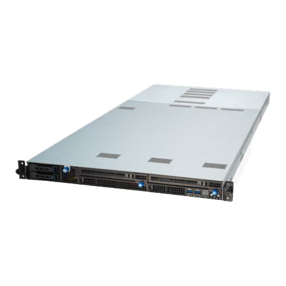
- Page 1 ESC4000 DHD G4 1U Rackmount Server User Guide...
- Page 2 ASUSTeK COMPUTER INC. (“ASUS”). ASUS provides this manual “as is” without warranty of any kind, either express or implied, including but not limited to the implied warranties or conditions of merchantability or fitness for a particular purpose. In no...
-
Page 3: Table Of Contents
Contents Safety information ..................... vii About this guide ....................... viii Chapter 1: Product Introduction System package contents ................. 1-2 Serial number label ..................1-3 System specifications ................1-4 Front panel features ................... 1-7 Rear panel features ..................1-7 Internal features ..................1-8 LED information .................. - Page 4 Onboard LEDs ..................4-10 Internal connectors .................. 4-12 Chapter 5: BIOS Setup Managing and updating your BIOS ............5-2 5.1.1 ASUS CrashFree BIOS 3 utility........... 5-2 5.1.2 ASUS EZ Flash Utility ..............5-3 5.1.3 BUPDATER utility ............... 5-4 BIOS setup program .................. 5-6 5.2.1...
- Page 5 Contents Performance Tuning menu ..............5-10 Advanced menu ..................5-11 5.5.1 Trusted Computing..............5-12 5.5.2 ACPI Settings ................5-12 5.5.3 Smart Settings................5-13 5.5.4 Super IO Configuration ............. 5-13 5.5.5 Serial Port Console Redirection ..........5-14 5.5.6 Onboard LAN Configuration ............. 5-16 5.5.7 APM ..................
- Page 6 RAID driver installation ................7-2 7.1.1 Creating a USB flash drive with RAID driver ....... 7-2 7.1.2 Installing the RAID controller driver..........7-2 Running the Support DVD ................. 7-5 Appendix Z11PG-D16-HD block diagram ................A-2 Notices ........................A-3 ASUS contact information ..................A-5...
-
Page 7: Safety Information
Safety information Electrical Safety • Before installing or removing signal cables, ensure that the power cables for the system unit and all attached devices are unplugged. • To prevent electrical shock hazard, disconnect the power cable from the electrical outlet before relocating the system. -
Page 8: About This Guide
About this guide Audience This user guide is intended for system integrators, and experienced users with at least basic knowledge of configuring a server. Contents This guide contains the following parts: Chapter 1: Product Introduction This chapter describes the general features of the server, including sections on front panel and rear panel specifications. - Page 9 Refer to the following sources for additional information, and for product and software updates. ASUS Control Center (ACC) user guide This manual tells how to set up and use the proprietary ASUS server management utility. ASUS websites The ASUS websites worldwide provide updated information for all ASUS hardware and...
-
Page 11: Chapter 1: Product Introduction
Chapter 1: Product Introduction Product Introduction This chapter describes the general features of the chassis kit. It includes sections on front panel and rear panel specifications. -
Page 12: System Package Contents
Check your system package for the following items. ESC4000 DHD G4 Chassis ASUS 1U Rackmount Chassis Motherboard ASUS Z11PG-D16-HD Series Server Board 1 x MB Support DVD 1 x External FAN with cage set Accessory box 4 x SATA cables 1 x GPU kit • ASUS System Web-based Management... -
Page 13: Serial Number Label
1.2 Serial number label Before requesting support from the ASUS Technical Support team, you must take note of the product’s serial number containing 12 characters such as xxS0xxxxxxxx. See the figure below. With the correct serial number of the product, ASUS Technical Support team members can then offer a quicker and satisfying solution to your problems. -
Page 14: System Specifications
System specifications The ASUS ESC4000 DHD G4 server features the ASUS Z11PG-D16-HD Series server board that supports Intel LGA 3647 Xeon processor from the Skylake F and Skylake-SP product ® ® family. ESC4000 DHD G4 Model Name 2 x Socket P (LGA 3647) - Page 15 1 x Storage Device Access LED 1 x Message LED Switch/LED 2 x LAN LEDs 1 x Q code LCD Rear Switch/LED: 1 x Message LED 1 x Storage Device LED 1 x Location LED (continued on the next page) ASUS ESC4000 DHD G4...
- Page 16 System specifications ESC4000 DHD G4 Model Name Security Options Trusted Platform Module (TPM 2.0) Software Management Out of Band Remote On-Board ASMB9-iKVM for KVM-over-IP Solution Management BSMI, CE, FCC (Class A) Regulatory Compliance 998m m x 439.5 mm x 43.6 mm (1U) Dimension (HH x WW x DD) 39.29” x 17.30” x 1.72”...
-
Page 17: Front Panel Features
Refer to the 1.7 LED information section for the LED descriptions. • The rear I/O ports do not appear on the rear panel if motherboard is not present. • The DM_LAN1 port is for ASUS ASMB9-iKVM controller only. ASUS ESC4000 DHD G4... -
Page 18: Internal Features
1.6 Internal features The barebone server includes the basic components as shown. Redundant power supply and power fan ASUS Z11PG-D16-HD server board System fans Storage device trays PCI-E x16 slots (Gen3 x16 Link) Low-profile PCI-E x16 slots with riser card (Gen3 x16 Link) The barebone server does not include a floppy disk drive or an optical drive. -
Page 19: Led Information
LAN is transmitting or receiving data LAN connection is present 1.7.2 Rear panel LEDs Message LED Storage device access LED Icon Display status Description Storage Device No activity Access LED Blinking Data activity System is normal; no incoming event Message LED A hardware monitor event is indicated ASUS ESC4000 DHD G4... -
Page 20: Lan (Rj-45) Leds
1.7.3 LAN (RJ-45) LEDs ACT/LINK LED SPEED LED ACT/LINK LED SPEED LED LAN1/LAN2 LEDs ACT/LINK LED SPEED LED Status Description Status Description No link 10 Mbps connection GREEN Linked ORANGE 100 Mbps connection BLINKING Data activity GREEN 1 Gbps connection Dedicated Management LAN (for ASMB9 and DM_LAN1) ACT/LINK LED SPEED LED Status Description Status Description No link 10 Mbps connection ORANGE Linked... -
Page 21: Storage Device Status Leds
Storage Device Access LED Description GREEN Storage device power ON Storage device has failed and should be swapped immediately GREEN/ Blinking RAID rebuilding GREEN/ Blinking Locate GREEN/ Storage device not found GREEN Blinking Read/write data from/into the storage device ASUS ESC4000 DHD G4 1-11... -
Page 22: Q-Code/Port 80 Status Leds
1.7.5 Q-Code/Port 80 status LEDs The Q-Code LED provides a 2-digit display that shows the status of your system. Refer to the Q-Code table of this user guide for more information about the 2-digit codes. Q-Code table Action PHASE POST CODE TYPE DESCRIPTION Progress First post code Progress Load BSP microcode Progress... - Page 23 0xA9 Progress BIOS Setup Utility start 0xAB Progress BIOS Setup Utility input wait 0xAD Progress Ready to boot event 0xAE Progress Legacy boot event 0xAA Progress APIC mode Operating system phase 0xAC Progress PIC mode ASUS ESC4000 DHD G4 1-13...
- Page 24 1-14 Chapter 1: Product Introduction...
-
Page 25: Chapter 2: Hardware Setup
Chapter 2: Hardware Setup Hardware Setup This chapter lists the hardware setup procedures that you have to perform when installing or removing system components. -
Page 26: Chassis Cover
Chassis cover There are two parts of the chassis cover you may remove. The diagrams in this section are for reference only. The system layout may vary with models, but the installation steps are the same for all models. To remove the rear chassis cover: Release the two (2) thumbscrews on the rear of the chassis. - Page 27 Slide the chassis cover towards the front to disengage it from the chassis and lift the chassis cover to completely remove it from the chassis. A protection film is pre-attached to the system cover before shipping. Please remove the protection film before turning on the system for proper heat dissipation. ASUS ESC4000 DHD G4...
-
Page 28: Air Duct
2.1.1 Air duct The diagrams in this section are for reference only. The system layout may vary with models, but the installation steps are the same for all models. To remove the air duct, lift the air duct by the indicated area (blue dot) to remove it from the chassis. -
Page 29: Central Processing Unit (Cpu)
Contact your retailer immediately if the PnP cap is missing, or if you see any damage to the PnP cap/socket contacts/motherboard components. ASUS will shoulder the cost of repair only if the damage is shipment/ transit-related. - Page 30 Align the triangle mark on the CPU with the triangle mark on the CPU Carrier (A), install the CPU into the CPU Carrier until it clicks firmly into place (B), and CPU Carrier then install the CPU and CPU Carrier into the heatsink until it clicks firmly in place (C).
-
Page 31: System Memory
128GB, 256GB, and 512GB DCPMMs into the DIMM sockets using the memory configurations in this section. • Refer to ASUS Server AVL for the updated list of compatible DIMMs. • When installing only one DIMM in a single CPU configuration, install the DIMM on either A1 or B1. - Page 32 Recommended memory configuration for 1 CPU Configuration 1 CPU Configuration 1 DIMM • 2 DIMMs • • 6 DIMMs • • • • • • • • • • • • • • 8 DIMMs Recommended memory configuration for 2 CPU Configuration 2 CPU Configuration 1 DIMM •...
- Page 33 AD - APP DIRECT MODE MM - MEMORY MODE AD+MM - MIXED MODE DRAM1 - RDIMM, RDIMM 3DS, LRDIMM, LRDIMM 3DS DRAM2 - RDIMM only DRAM3 - RDIMM, RDIMM 3DS, LRDIMM DCPMM - DC PERSISTENT MEMORY ASUS ESC4000 DHD G4...
- Page 34 2 CPU Configuration (symmetric population) 2 CPU Configuration (symmetric population) Modes DIMM_C1 DIMM_B1 DIMM_A2 DIMM_A1 DRAM 1 DRAM 1 DCPMM DRAM 1 DRAM 2 DRAM 2 DCPMM DRAM 2 DRAM 3 DRAM 3 DCPMM DRAM 3 AD+MM DCPMM DRAM 1 DRAM1 DCPMM DRAM 1...
- Page 35 Asymmetric Population (2nd Socket has no DCPMM DIMM) Modes DIMM_M1 DIMM_L1 DIMM_K2 DIMM_K1 DRAM 1 DRAM 1 DRAM 1 AD - APP DIRECT MODE DRAM1 - RDIMM, RDIMM 3DS, LRDIMM, LRDIMM 3DS DCPMM - DC PERSISTENT MEMORY ASUS ESC4000 DHD G4 2-11...
- Page 36 2 CPU Configuration with 2 DCPMM DIMMs (asymmetric population) 2 CPU Configuration (asymmetric population) Modes DIMM_C1 DIMM_B1 DIMM_A2 DIMM_A1 DRAM 1 DRAM 1 DCPMM DRAM 1 2 CPU Configuration (asymmetric population) Modes DIMM_F1 DIMM_E1 DIMM_D2 DIMM_D1 DRAM 1 DRAM 1 DRAM 1 2 CPU Configuration (asymmetric population) Modes...
- Page 37 To install two or more DIMMs, refer to the user guide bundled in the motherboard package. • Refer to www.asus.com for vendor lists of the memory modules. Removing a DIMM from a single clip DIMM socket Press the retaining clip outward to unlock the DIMM.
-
Page 38: Storage Devices
Storage devices The ESC4000 DHD G4 series supports 2.5-inch storage devices. The storage device installed in the storage device bay connects to the motherboard via the backplane. Storage bay 1 Storage bay 3 Storage bay 4 Storage bay 2 2.4.1 Installing a storage device into bay 1 or 2 Press the spring lock. -
Page 39: Installing A Storage Device Into Bay 3 Or 4
Hold the storage bay release thumbscrew and swing the storage device drawer open. DO NOT open the storage device drawer beyond 45 degrees. The storage device drawer is designed to open up to 45 degrees only. ASUS ESC4000 DHD G4 2-15... - Page 40 Press the spring lock. Pull the tray lever outwards to remove the storage device tray. Prepare the storage device and the bundled set of screws. Place the storage device into the tray (A) then secure it with four screws (B). 2-16 Chapter 2: Hardware Setup...
- Page 41 • The storage device tray is correctly placed when its front edge aligns with the bay edge. Swing the storage device drawer close. Secure the storage bay release thumbscrew to complete. ASUS ESC4000 DHD G4 2-17...
-
Page 42: Expansion Slots
Expansion slots Ensure to unplug the power cord before adding or removing expansion cards. Failure to do so may cause you physical injury and damage motherboard components. Riser card 1 Riser card 5 Riser card 2 Riser card 3 Riser card 4 2-18 Chapter 2: Hardware Setup... -
Page 43: Installing An Expansion Card Into Riser Card 1
PCI-E slot on the motherboard (B). Release the thumbscrew on the PCI-E card secure tab (A), then lift open the PCI-E card secure tab (B). Remove the screw from the metal bracket. ASUS ESC4000 DHD G4 2-19... - Page 44 Remove the metal bracket from the riser card. (for Quadro and Tesla GPU cards only) Hook the spacer plate onto the riser card (A), then slide it to the left to secure it in place (B). Prepare the expansion card. Before installing an expansion card, read the documentation that came with it and ensure to make the necessary hardware settings.
- Page 45 Close the PCI-E card secure tab (A), then secure the thumbscrew on the PCI-E card secure tab. Secure the thumbscrew to the expansion card (A), then secure a screw to the expansion card (B). ASUS ESC4000 DHD G4 2-21...
- Page 46 (for ASUS GPU cards only) Connect a compatible power connector board into the ASUS GPU card. 8 pin and 8 pin power connector board 6 pin and 8 pin power connector board Connect the power cable into the power connector.
- Page 47 (for ASUS GPU cards only) Peel the mylar off from the bottom of the chassis (A), then pry the metal cover on the chassis until it pops off (B). Due to the design of ASUS GPU cards, the metal cover on bottom the chassis must be removed to allow the ASUS GPU card to fit properly inside the server system.
- Page 48 Connect the other end of the power cable to the VGAPWR4 connector on the motherboard to complete. 2-24 Chapter 2: Hardware Setup...
-
Page 49: Installing An Expansion Card Into Riser Card 2, 3, Or 4
Release the two (2) thumbscrews that secure the riser card to the chassis. Firmly hold the riser card by the indicated areas (A), then pull it up to detach it from the PCI-E slot on the motherboard (B). ASUS ESC4000 DHD G4 2-25... - Page 50 Remove the screws from the riser GPU bracket (A), then remove the riser GPU bracket (B). (for Quadro and Tesla GPU cards only) Hook the spacer plate onto the riser card. Prepare the expansion card. Before installing an expansion card, read the documentation that came with it and ensure to make the necessary hardware settings.
- Page 51 Quadro and Tesla GPU cards Align the riser GPU bracket to the GPU card (A), then secure the riser GPU bracket to the GPU card with two screws (B). ASUS GPU cards Quadro and Tesla GPU cards ASUS ESC4000 DHD G4 2-27...
- Page 52 Align and insert the golden finger connectors of the expansion card to the PCI-E slot connector on the riser card (A), then secure the riser GPU bracket to the riser card with two screws (B). Secure the thumbscrew to the expansion card (A), then secure a screw to the expansion card (B).
- Page 53 (for ASUS GPU cards only) Connect a compatible power connector board into the ASUS GPU card. 8 pin and 8 pin power connector board 6 pin and 8 pin power connector board Connect the power cable into the power connector.
- Page 54 Pass the power cable through the riser card as shown below. Firmly hold the riser card by the indicated areas (A), then align and insert the riser card and expansion card assembly into the PCI-E slot on the motherboard (B). Ensure that the alignment three standoffs are aligned correctly with the riser card.
- Page 55 Connect the other end of the power cable to the VGAPWR1 connector on the motherboard. Connect the GPU on riser card 2 to VGAPWR3, and connect the GPU on riser card 3 to VGAPWR2. ASUS ESC4000 DHD G4 2-31...
- Page 56 Gently press down the power cable in the indicated area so that the power cable does not extend higher than the riser card. Leaving the power cable extending higher than the riser card will prevent the chassis cover from closing properly and may damage the power cable. Repeat steps 1 to 16 for the other GPU cards on riser card 2 and 3.
-
Page 57: Installing An Expansion Card Into Riser Card 5
Gasket Remove the screw from the metal bracket (A), then remove the metal bracket (B). ASUS ESC4000 DHD G4 2-33... - Page 58 Prepare the expansion card. Before installing an expansion card, read the documentation that came with it and ensure to make the necessary hardware settings. Align and insert the golden finger connectors of the expansion card to the PCI-E slot connector on the riser card (A), then secure the expansion card with the screw removed earlier (B).
-
Page 59: Installing An M.2 Expansion Card
• Please pay attention when removing the screw, the stand screw might be removed together with it. • Ensure that the M.2 card is positioned between the screw and the stand screw before securing it. ASUS ESC4000 DHD G4 2-35... -
Page 60: Configuring An Expansion Card
2.5.5 Configuring an expansion card After installing the expansion card, configure it by adjusting the software settings. Turn on the system and change the necessary BIOS settings, if any. See Chapter 5 for information on BIOS setup. Assign an IRQ to the card. Refer to the Standard Interrupt assignments table for more information. -
Page 61: Cable Connections
Power supply PMBus connector (connects to BPPWR12 on storage device backplane) OCU-PCIE to PCIE connector (connects to OCUPCIE1-4 on storage device backplane) LED panel connector (connects to BP12_CON1, BP3_CON1, and BP4_CON1 on storage device backplanes) System fan connectors (connects to system fans) ASUS ESC4000 DHD G4 2-37... -
Page 62: Storage Device Backplane Cabling
Storage device backplane cabling Connects to SATAPWR1 on motherboard and Connects to OCUPCIE1 BPPWR3 on backplane on motherboard Connects to LED_PANEL1 Connects to OCUPCIE2 on motherboard on motherboard Connects to storage device in storage device bay 1 and 2 Connects to LED_PANEL1 Connects to LED_PANEL1 on motherboard on motherboard... -
Page 63: Optional Components
To reinstall the system fans, insert the fan into the fan cage. Ensure the fan connector is seated firmly within the cable holder and connected to the motherboard. ASUS ESC4000 DHD G4 2-39... -
Page 64: Redundant Power Supply Units
2.8.2 Redundant power supply units We recommend that you use both of your hands in performing the following steps. To replace a power supply unit (PSU): Lift up the PSU lever. Hold the PSU lever, press the PSU latch (A) and carefully pull the PSU out of the system chassis (B). - Page 65 (e.g. 1 x 1620 W + 1 x 2000 W) may yield unstable results and potential damage to your system. • For a steady power input, use only the power cables that come with the server system package. ASUS ESC4000 DHD G4 2-41...
-
Page 66: External Fan Cage (Optional)
2.8.3 External fan cage (optional) When you are using high performance expansion cards in riser card 1, installing an optional external fan cage may improve the performance of your server system. To install an external fan cage: Pry the external fan cage metal cover until it pops off to reveal the cable opening. External fan cage metal cover Pass the external fan cage cable through the cable opening, ensure that the cable is routed next to the cable standoff. - Page 67 Align the external fan cage with the screw holes on the rear panel (A), then secure the external fan cage to the rear panel (B). Connect the external fan cage cable to the CPU_FAN1 connector on the motherboard to complete. ASUS ESC4000 DHD G4 2-43...
- Page 68 2-44 Chapter 2: Hardware Setup...
-
Page 69: Chapter 3: Installation Options
Chapter 3: Installation Options Installation Options This chapter describes how to install the optional components and devices into the barebone server. -
Page 70: Rail Kit
Rail Kit The rail kit package includes: 2 x 1200 mm rack rails Rack rails Rear end Front end 2 x M5X20L screws 2 x M4X4L screws 8 x ø7.1 screws 8 x #10-32 screws • The bundled screw package includes different types of screws for you to choose from, not all screws are required for the installation. • Package content and specifications are subject to change without notice. 3.1.1 Selecting rack rail cabinets Refer to the guide below for more information on selecting a rack rail cabinet and rack rail for... -
Page 71: Attaching The Rack Rails
To install the rack rails into the rack: Select a desired space on the rack. A 1U space consists of three square mounting holes with two thin lips on the top and the bottom. Align and insert the front end of the Front rack post Front end of rack rail appropriate rack rail (left and right) into the front rack post. ASUS ESC4000 DHD G4... - Page 72 Press the spring lock on the rear end Rear rack post of the rack rail and insert the studs into Spring lock the selected mounting holes on the rear rack post. Rear end of rack rail Slide the intermediate rail out of the outer rail until it clicks to a stop. Intermediate rail Outer rail Slide the inner rail out of the intermediate rail until it clicks to a stop. Slide the white release tab outwards and remove the inner rail completely from the intermediate rail. Inner rail Intermediate rail Blue release tab White release tab Repeat steps 2 to 5 for the other rack rail. Ensure that the installed rack rails (left and right) are aligned, secured, and stable in place. Chapter 3: Installation Options...
- Page 73 Align the inner rails with the studs on both sides of the server system, install the inner rails to the server system, then slide the inner rails toward the rear of the server system until it locks in place. Secure the inner rails on both sides of the server system using the M4X4L screws. ASUS ESC4000 DHD G4...
- Page 74 Align the server system and gently insert it into the rack rails. 10. (optional) Use the M5X20L screws to Front rack post Front end of rack rail secure the rack rails to the rack post. 11. Gently push the server system until it is completely installed into the rack rail. (optional) If the inner rail clicks to a stop while you are installing the server system into the rack rails, slide the blue release tab outwards and gently push the server system until it is completely installed into the rack rail. Inner rail Intermediate rail Blue release tab White release tab Chapter 3: Installation Options...
- Page 75 ESC4000 DHD G4 Front View ASUS ESC4000 DHD G4...
-
Page 76: Cable Management Arm
Cable management arm You can install an additional cable management arm (CMA) to the rack rails to help you manage the cables from your server system. The CMA is designed with movable parts that allow you to move the server system along the rack rail without the need to remove the CMA. Outer receptor Hook and loop fasteners Inner receptor Pivot receptor Cable fasteners 3.2.1 Attaching the cable management arm Installing the cable management arm To install the cable management arm: 1. Install the rack rails into the rack. Refer to section 3.1 Rail Kit for the steps on installing the rack rails into the rack. Press the round button on the pivot receptor, then rotate the pivot receptor to the left or right for a left pivot configuration or right pivot configuration. - Page 77 The installation steps in this section uses a Left pivot configuration as an example, the installation steps for a Right pivot configuration is similar. Align and connect the inner receptor on the CMA with the connector on the inner rail. Align and connect the outer receptor on the CMA with the connector on the intermediate rail. ASUS ESC4000 DHD G4...
- Page 78 Align and connect the pivot receptor on the CMA with the connector on the other intermediate rail. Pass the cables from the server system through the hook and loop fasteners and the cable fasteners on the CMA to complete. Hook and loop fasteners Cable fasteners 3-10 Chapter 3: Installation Options...
-
Page 79: Chapter 4: Motherboard Information
Chapter 4: Motherboard Information Motherboard Infor- mation This chapter gives information about the motherboard that comes with the server. This chapter includes the motherboard layout, jumper settings, and connector locations. -
Page 80: Motherboard Layout
Motherboard layout Chapter 4: Motherboard Information... - Page 81 24. TPM connector 4-15 25. Smart Ride Through jumper 26. DDR4 Thermal Event jumper 27. USB 3.2 Gen 1 connector 4-19 28. DIMM slots 29. System Panel connector 4-18 30. CPU socket 31. M.2 slot 4-17 ASUS ESC4000 DHD G4...
-
Page 82: Jumpers
Jumpers Clear RTC RAM jumper The Clear RTC RAM jumper allows you to clear the Real Time Clock (RTC) RAM in the CMOS, which contains the date, time, system passwords, and system setup parameters. To erase the RTC RAM: Turn OFF the computer and unplug the power cord. Short-circuit pin 1-2 with a metal object or jumper cap for about 5-10 seconds. - Page 83 The VGA Controller jumper allows you to enable or disable the onboard VGA controller. Set to pins 1-2 to enable the onboard VGA. ME Firmware Force Recovery jumper Set to pins 2-3 to force Intel Management Engine (ME) boot from recovery mode ® when the ME becomes corrupted. ASUS ESC4000 DHD G4...
- Page 84 Baseboard Management Controller setting The Baseboard Management Controller jumper allows you to enable or disable the on-board BMC. Ensure to set this BMC jumper to Enable to avoid system fan control and hardware monitor error. Smart Ride Through jumper Set to pins 1-2 to enable the Smart Ride Through (SmaRT) feature to allow uninterrupted operation of the system during an AC loss event.
- Page 85 DDR4 Thermal Event jumper Set to pins 1-2 to enable DDR4 DIMM thermal sensing event. LED Select jumper The LED Select jumper allows you to select which source the LED will function. ASUS ESC4000 DHD G4...
- Page 86 PCH_MFG1 jumper The PCH_MFG1 jumper allows you to update the BIOS ME block. DMLAN jumper Set to pins 2-3 to force the DMLAN IP to static mode (IP=10.10.10.10, submask=255.255.255.0). Chapter 4: Motherboard Information...
- Page 87 IPMI SW jumper The IPMI SW jumper allows you to select which protocol in the GPU sensor to function. ASUS ESC4000 DHD G4...
-
Page 88: Onboard Leds
Onboard LEDs Standby Power LED The Standby Power LED lights up to indicate that the system is ON, in sleep mode, in soft-off mode, or connected to a power source. This is a reminder that you should shut down the system and unplug the power cable before removing or plugging in any motherboard component. - Page 89 Catastrophic Error LED The Catastrophic Error LED indicates that the system has experienced a fatal or catastrophic error and cannot continue to operate. ASUS ESC4000 DHD G4 4-11...
-
Page 90: Internal Connectors
Internal connectors SATA 6Gb/s connector The SATA 6Gb/s connector allows you to connect SATA devices such as optical disc drives and hard disk drives via a SATA cable. The actual data transfer rate depends on the speed of Serial ATA hard disks installed. OCUPCIE connector Connects the PCIE signal to the backplane. - Page 91 Connect the fan cable to the fan connector on the motherboard, ensuring that the black wire of each cable matches the ground pin of the connector. • DO NOT forget to connect the fan cables to the fan connectors. Insufficient air flow inside the system may damage the motherboard components. • Ensure the cable is fully inserted into the connector. ASUS ESC4000 DHD G4 4-13...
- Page 92 Storage Add-on Card LED connector The Storage Add-on Card LED connector allows you to connect the storage device activity LED cable from a storage add-on card. The Storage Device status LED lights up or blinks when data is read from or written to the storage device add-on card. Refer to section LED information for the exact location of the Storage Device status LED.
- Page 93 The serial port module is purchased separately. TPM connector The TPM connector allows you to connect a Trusted Platform Module (TPM). A TPM securely stores keys, digital certificates, passwords, data, and also helps enhance network security, protect digital identities, and ensures platform integrity. The TPM is purchased separately. ASUS ESC4000 DHD G4 4-15...
- Page 94 System Management Bus connector The System Management Bus (SMBus) connector allows you to connect SMBus devices. This connector is generally used for communication with the system and power management-related tasks. LED Panel connector Connects the LED panel signal to the backplane. Chapter 4: Motherboard Information 4-16...
- Page 95 This connector supports type 2280 / 22110 devices on both PCI-E and SATA interface. The M.2 (NGFF) device is purchased separately. SATA Power connector The SATA Power connector allow you to connect power from the motherboard to the backplane. The power supply plug is designed to fit in only one orientation, find the proper orientation and push down firmly until the power supply plug is fully inserted. ASUS ESC4000 DHD G4 4-17...
- Page 96 System Panel connector Connects the panel signal to the front panel. Serial General Purpose Input/Output connector The Serial General Purpose Input/Output (SGPIO) connector allows you to connect the Intel Rapid Storage Technology Enterprise SGPIO interface. The SGPIO interface controls the LED pattern generation, device information, and general purpose data. Chapter 4: Motherboard Information 4-18...
- Page 97 The USB 3.2 Gen 1 connector provides data transfer speeds of up to 5 Gb/s. The plugged USB 3.2 Gen 1 device may run on xHCI or EHCI mode depending on the operating system’s setting. ASUS ESC4000 DHD G4 4-19...
- Page 98 MicroSD card slot The microSD card slot allows you to install a microSD memory card v2.00 (SDHC) / v3.00 (SDXC) to log BMC events. Disconnect all power (including redundant PSUs) from the existing system before you add or remove a memory card, then reboot the system to access the memory card. Some memory cards may not be compatible with your motherboard.
- Page 99 VGA Power connectors These connectors are for the power supply plugs that connects to the GPU cards. The power supply plugs are designed to fit these connectors in only one orientation. Find the proper orientation and push down firmly until the connectors completely fit. ASUS ESC4000 DHD G4 4-21...
- Page 100 Chapter 4: Motherboard Information 4-22...
-
Page 101: Chapter 5: Bios Setup
Chapter 5: BIOS Setup BIOS Setup This chapter tells how to change system settings through the BIOS Setup menus and describes the BIOS parameters. -
Page 102: Managing And Updating Your Bios
BIOS in the future. Copy the original motherboard BIOS using the BUPDATER utility. 5.1.1 ASUS CrashFree BIOS 3 utility The ASUS CrashFree BIOS 3 is an auto recovery tool that allows you to restore the BIOS file when it fails or gets corrupted during the updating process. You can update a corrupted BIOS file using a USB flash drive that contains the updated BIOS file. -
Page 103: Asus Ez Flash Utility
5.1.2 ASUS EZ Flash Utility The ASUS EZ Flash Utility feature allows you to update the BIOS without having to use a DOS-based utility. Before you start using this utility, download the latest BIOS from the ASUS website at www.asus.com. To update the BIOS using EZ Flash Utility: Insert the USB flash disk that contains the latest BIOS file into the USB port. Enter the BIOS setup program. Go to the Tool menu then select Start EzFlash. -
Page 104: Bupdater Utility
The BUPDATER utility allows you to update the BIOS file in the DOS environment using a bootable USB flash disk drive with the updated BIOS file. Updating the BIOS file To update the BIOS file using the BUPDATER utility: Visit the ASUS website at www.asus.com and download the latest BIOS file for the motherboard. Save the BIOS file to a bootable USB flash disk drive. Copy the BUPDATER utility (BUPDATER.exe) from the ASUS support website at www.asus.com/support to the bootable USB flash disk drive you created earlier. Boot the system in DOS mode, then at the prompt, type: BUPDATER /i[filename].CAP where [filename] is the latest or the original BIOS file on the bootable USB flash disk drive, then press <Enter>. A:\>BUPDATER /i[file name].CAP Chapter 5: BIOS Setup... - Page 105 DO NOT shut down or reset the system while updating the BIOS to prevent system boot failure! The utility returns to the DOS prompt after the BIOS update process is completed. Reboot the system from the hard disk drive. The BIOS update is finished! Please restart your system. C:\> ASUS ESC4000 DHD G4...
-
Page 106: Bios Setup Program
If the system becomes unstable after changing any BIOS settings, load the default settings to ensure system compatibility and stability. Press <F5> and select Yes to load the BIOS default settings. • The BIOS setup screens shown in this section are for reference purposes only, and may not exactly match what you see on your screen. • Visit the ASUS website (www.asus.com) to download the latest BIOS file for this motherboard. Chapter 5: BIOS Setup... -
Page 107: Bios Menu Screen
For changing the event log settings Server Mgmt For changing the Server Mgmt settings For changing the security settings Security Boot For changing the system boot configuration Tool For configuring options for special functions For selecting the exit options Save & Exit To select an item on the menu bar, press the right or left arrow key on the keyboard until the desired item is highlighted. ASUS ESC4000 DHD G4... -
Page 108: Menu Items
5.2.3 Menu items The highlighted item on the menu bar displays the specific items for that menu. For example, selecting Main shows the Main menu items. The other items (such as Advanced) on the menu bar have their respective menu items. 5.2.4 Submenu items A solid triangle before each item on any menu screen means that the item has a submenu. To display the submenu, select the item then press <Enter>. -
Page 109: Main Menu
Main menu When you enter the BIOS Setup program, the Main menu screen appears. The Main menu provides you an overview of the basic system information, and allows you to set the system date, time, language, and security settings. 5.3.1 System Date [Day xx/xx/xxxx] Allows you to set the system date. 5.3.2 System Time [xx:xx:xx] Allows you to set the system time. ASUS ESC4000 DHD G4... -
Page 110: Performance Tuning Menu
Performance Tuning menu The Performance Tuning menu items allow you to change performance related settings for different scenarios. Optimized Performance Setting [Default] Allows you to select performance settings for different scenarios. [Default] Default settings. [By Benchmark] O ptimize for different kinds of benchmarks. Select this option, then select a benchmark type from the >> list. [By Workload] O ptimize for different kinds of workloads. Select this option, then select a workload type from the >>... -
Page 111: Advanced Menu
Advanced menu The Advanced menu items allow you to change the settings for the CPU and other system devices. Take caution when changing the settings of the Advanced menu items. Incorrect field values can cause the system to malfunction. ASUS ESC4000 DHD G4 5-11... -
Page 112: Trusted Computing
5.5.1 Trusted Computing Configuration Security Device Support [Disabled] Allows you to enable or disable the BIOS support for security device. Configuration options: [Disabled] [Enabled] Disable Block Sid [Disabled] Allows you to enable or disable the Block Sid. Configuration options: [Disabled] [Enabled] 5.5.2 ACPI Settings Enable ACPI Auto Configuration [Disabled] Allows you to enable or disable the BIOS ACPI Auto Configuration. Configuration options: [Disabled] [Enabled] Enable Hibernation [Enabled] Allows you to enable or disable the ability of the system to hibernate (OS/Sleep State). -
Page 113: Smart Settings
Allows you to enable or disable Serial Port. Configuration options: [Disabled] [Enabled] The following item appears only when you set Serial Port to [Enabled]. Change Settings [Auto] Allows you to choose the setting for Super IO device. Configuration options: [ Auto] [IO=3F8h; IRQ=4;] [IO=3F8h; IRQ=3, 4, 5, 6, 7, 9, 10, 11, 12;] [IO=2F8h; IRQ=3, 4, 5, 6, 7, 9, 10, 11, 12;] [IO=3E8h; IRQ=3, 4, 5, 6, 7, 9, 10, 11, 12;] [IO=2E8h; IRQ=3, 4, 5, 6, 7, 9, 10, 11, 12;] ASUS ESC4000 DHD G4 5-13... -
Page 114: Serial Port Console Redirection
5.5.5 Serial Port Console Redirection COM1/COM2 Console Redirection [Disabled] Allows you to enable or disable the console redirection feature. Configuration options: [Disabled] [Enabled] The following item appears only when you set Console Redirection to [Enabled]. Console Redirection Settings These items become configurable only when you enable the Console Redirection item. The settings specify how the host computer and the remote computer (which the user is using) will exchange data. - Page 115 This allows you to select the FunctionKey and Keypad on Putty. Configuration options: [VT100] [LINUX] [XTERMR6] [SCO] [ESCN] [VT400] Legacy Console Redirection Settings Legacy Console Redirection Port [COM1] Allows you to select a COM port to display redirection of Legacy OS and Legacy OPROM Messages. Configuration options: [COM1] [COM2] Resolution [80x24] This allows you to set the number of rows and columns supported on the Legacy OS. Configuration options: [80x24] [80x25] Redirect After POST [Always Enable] This setting allows you to specify if Bootloader is selected than Legacy console redirection. Configuration options: [Always Enable] [Bootloader] ASUS ESC4000 DHD G4 5-15...
-
Page 116: Onboard Lan Configuration
Serial Port for Out-of-Band Management/Windows Emergency Management Services (EMS) Console Redirection [Disabled] Allows you to enable or disable the console redirection feature. Configuration options: [Disabled] [Enabled] The following item appears only when you set Console Redirection to [Enabled]. Console Redirection Settings Out-of-Band Mgmt Port [COM1] Microsoft Windows Emergency Management Services (EMS) allow for remote management of a Windows Server OS through a serial port. -
Page 117: Apm
Restore AC Power Loss [Last State] When set to [Power Off], the system goes into off state after an AC power loss. When set to [Power On], the system will reboot after an AC power loss. When set to [Last State], the system goes into either off or on state, whatever the system state was before the AC power loss. Configuration options: [Power Off] [Power On] [Last State] Power On By PCIE [Disabled] [Disabled] Disables the PCIE devices to generate a wake event. [Enabled] Enables the PCIE devices to generate a wake event. Power On By RTC [Disabled] [Disabled] Disables RTC to generate a wake event. [Enabled] W hen set to [Enabled], the items RTC Alarm Date (Days) and Hour/Minute/Second will become user-configurable with set values. ASUS ESC4000 DHD G4 5-17... -
Page 118: Pci Subsystem Settings
5.5.8 PCI Subsystem Settings Allows you to configure PCI, PCI-X, and PCI Express Settings. Load RT32 Image [Enabled] This option allows you to enable or disable RT32 Image Loading. Configuration options: [Disabled] [Enabled] Above 4G Decoding [Enabled] Allows you to enable or disable 64-bit capable devices to be decoded in above 4G address space. It only works if the system supports 64-bit PCI decoding. Configuration options: [Disabled] [Enabled] The following item appears only when you set Above 4G Decoding to [Enabled]. First VGA 4G Decode [Above 4G] Configuration options: [Auto] [Above 4G] SR-IOV Support [Enabled]... - Page 119 If supported by hardware and set to ‘Enabled’, this function initiates Atomc0p Requests only if Bus Master Enable bit is in the Command Register set. Configuration options: [Disabled] [Enabled] Atomic0p Egress Blocking [Disabled] If supported by hardware and set to ‘Enabled’, outbound Atomic0p Requests via Egress Ports will be blocked. Configuration options: [Disabled] [Enabled] ID0 Request Enable [Disabled] If supported by hardware and set to ‘Enabled’, this permits setting the number of ID- Based Ordering (ID0) bit (Attribute [2]) requests to be initiated. Configuration options: [Disabled] [Enabled] ID0 Completion Enable [Disabled] If supported by hardware and set to ‘Enabled’, this permits setting the number of ID- Based Ordering (ID0) bit (Attribute [2]) requests to be initiated. Configuration options: [Disabled] [Enabled] ASUS ESC4000 DHD G4 5-19...
- Page 120 LTR Mechanism Enable [Disabled] If supported by hardware and set to ‘Enabled’, this enables the Latency Tolerance Reporting (LTR) Mechanism. Configuration options: [Disabled] [Enabled] End-End TLP Prefix Blocking [Disabled] If supported by hardware and set to ‘Enabled’, this function will block forwarding of TLPs containing End-End TLP Prefixes. Configuration options: [Disabled] [Enabled] PCI Express GEN2 Link Register Target Link Speed [Auto] Configuration options: [ Auto] [Force to 2.5 GT/s] [Force to 5.0 GT/s] [Force to 8.0 GT/s] [Force to 16.0 GT/s] Clock Power Management [Disabled] Configuration options: [Disabled] [Enabled] Compliance SOS [Disabled] Configuration options: [Disabled] [Enabled] Hardware Autonomous Width [Enabled] Configuration options: [Enabled] [Disabled] Hardware Autonomous Speed [Enabled] Configuration options: [Enabled] [Disabled]...
-
Page 121: Usb Configuration
USB Mass Storage Driver Support [Enabled] Allows you to enable or disable the USB Mass Storage driver support. Configuration options: [Disabled] [Enabled] Mass Storage Devices These items allows you to select the mass storage device emulation type. Configuration options: [Auto] [Floppy] [Forced FDD] [Hard Disk] [CD-ROM] ASUS ESC4000 DHD G4 5-21... -
Page 122: Csm Configuration
5.5.10 CSM Configuration CSM Support [Enabled] This option allows you to enable or disable CSM Support. Configuration options: [Disabled] [Enabled] The following item appears only when CSM Support is set to [Enabled]. GateA20 Active [Upon Request] This allows you to set the GA20 option. Configuration options: [Upon Request] [Always] Option ROM Messages [Force BIOS] This allows you to set the display mode for option ROM. -
Page 123: Nvme Configuration
The following item appears only when Network stack is set to [Enabled]. Ipv4 PXE Support [Disabled] Enables or disables the Ipv4 PXE Boot Support. If disabled, Ipv4 PXE boot option will not be created. Configuration options: [Disabled] [Enabled] Ipv4 HTTP Support [Disabled] Enables or disables the Ipv4 HTTP Boot Support. If disabled, Ipv4 HTTP boot option will not be created. Configuration options: [Disabled] [Enabled] Ipv6 PXE Support [Disabled] Enables or disables the Ipv6 PXE Boot Support. If disabled, Ipv6 PXE boot option will not be created. Configuration options: [Disabled] [Enabled] ASUS ESC4000 DHD G4 5-23... -
Page 124: Iscsi Configuration
Ipv6 HTTP Support [Disabled] Enables or disables the Ipv6 HTTP Boot Support. If disabled, Ipv6 HTTP boot option will not be created. Configuration options: [Disabled] [Enabled] PXE boot wait time [0] Wait time to press ESC key to abort the PXE boot. Media detect time [1] Wait time (in seconds) to detect media. 5.5.14 iSCSI Configuration Allows you to configure the iSCSi parameters. Platform Configuration menu The IntelRCSetup menu items allow you to change the platform settings. Chapter 5: BIOS Setup 5-24... -
Page 125: Pch Configuration
Allows you to enable or disable the SATA Controller. Configuration options: [Disabled] [Enabled] Configure sSATA as [AHCI] Allows you to identify the SATA port connected to Solid State Drive or Hard Disk Drive. Configuration options: [IDE] [AHCI] [RAID] Support Aggressive Link Power Management [Enabled] Allows you to enable or disable the Support Aggressive Link Power (SALP) Management. Configuration options: [Disabled] [Enabled] SATA Port 1-4 Port 1-4 Allows you to enable or disable the SATA port. Configuration options: [Disabled] [Enabled] ASUS ESC4000 DHD G4 5-25... - Page 126 USB Configuration USB Precondition [Disabled] Allows you to enable or disable precondition work on USB host controller and root ports for faster enumeration. Configuration options: [Disabled] [Enabled] XHCI Manual Mode [Disabled] This option is used by validation. Configuration options: [Disabled] [Enabled] The following items appears only when the XHCI Manual Mode is set to [Enabled]. Trunk Clock Gating (BTCG) [Enabled] Allows you to enable or disable BTCG.
-
Page 127: Miscellaneous Configuration
5.6.2 Miscellaneous Configuration Active Video [Onboard Device] Allows you to select the video type. Configuration options: [Auto] [Onboard Device] [Offboard Device] 5.6.3 Server ME Configuration Displays the Server ME Technology parameters on your system. ASUS ESC4000 DHD G4 5-27... -
Page 128: Runtime Error Logging Support
5.6.4 Runtime Error Logging Support Runtime Error Logging System Errors [Enabled] This item allows you to enable or disable System Errors. Configuration options: [Disabled] [Enabled] Whea Settings Whea Support [Enabled] This item allows you to enable or disable the WHEA support. Configuration options: [Disabled] [Enabled] Socket Configuration menu The IntelRCSetup menu items allow you to change the socket settings. Chapter 5: BIOS Setup 5-28... -
Page 129: Processor Configuration
Configuration options: [Disabled] [Enabled] Enable Intel(R) TXT [Disabled] Forces the XD feature log to always return 0 when disabled. Configuration options: [Disabled] [Enabled] VMX [Enabled] Enables the Vanderpool Technology. Takes effect after reboot. Configuration options: [Disabled] [Enabled] Enable SMX [Disabled] Enables the Safer Mode Extensions. Configuration options: [Disabled] [Enabled] Hardware Prefetcher [Enabled] This Item allows you to turn on/off the mid level cache(L2) streamer prefetcher. Configuration options: [Disabled] [Enabled] L2 RFO Prefetch Disable [Disabled] This Item allows you to turn on/off L2 RFO prefetcher. Configuration options: [Disabled] [Enabled] ASUS ESC4000 DHD G4 5-29... -
Page 130: Common Refcode Configuration
Adjacent Cache Prefetch [Enabled] This Item allows you to turn on/off prefetching of adjacent cache lines. Configuration options: [Disabled] [Enabled] DCU Streamer Prefetcher [Enabled] This Item allows you to enable or disable prefetcher of next L1 data line. Configuration options: [Disabled] [Enabled] DCU IP Prefetcher [Enabled] This Item allows you to enable or disable prefetch of next L1 line based upon sequential load history. Configuration options: [Disabled] [Enabled] LLC Prefetch [Disabled] This Item allows you to enable or disable LLC Prefetch on all threads. Configuration options: [Disabled] [Enabled] DCU Mode [32K 8Way Without ECC] Configuration options: [32K 8Way Without ECC] [16K 4Way With ECC] Extended APIC [Disabled] This Item allows you to enable or disable the extended APIC support. -
Page 131: Upi Configuration
Link L0p Enable [Auto] Configuration options: [Disabled] [Enabled] [Auto] Link L1 Enable [Auto] Configuration options: [Disabled] [Enabled] [Auto] Directory Mode Enable [Enabled] Configuration options: [Disabled] [Enabled] SNC [Disabled] Configuration options: [Disabled] [Enabled] [Auto] KTI Prefetch [Enabled] Configuration options: [Disabled] [Enabled] Local/Remote Threshold [Auto] Configuration options: [Disabled] [Auto] [Low] [Medium] [High] Stale AtoS [Auto] Configuration options: [Disabled] [Enabled] [Auto] LLC dead line alloc [Enabled] Configuration options: [Disabled] [Enabled] [Auto] ASUS ESC4000 DHD G4 5-31... -
Page 132: Memory Configuration
5.7.4 Memory Configuration Enforce POR [Auto] Allows you to enforce POR restrictions for DDR4 frequency and voltage programming. Configuration options: [Auto] [POR] [Disabled] Memory Frequency [Auto] Allows you to select the memory frequency setting. Configuration options: [Auto] [1800] - [3000-OvrClk] Data Scrambling for DDR4 [Auto] Allows you to enable or disable data scrambling. Configuration options: [Auto] [Disabled] [Enabled] Memory Topology Displays memory topology with DIMM population information. - Page 133 Allows you to enable or disable UEFI ARM Mirror. Configuration options: [Disabled] [Enabled] Memory Rank Sparing [Disabled] Allows you to enable or disable Memory Rank Sparing Configuration options: [Disabled] [Enabled] Patrol Scrub [Enabled] Allows you to enable or disable Patrol Scrub. Configuration options: [Disabled] [Enabled] NGN Configuration Average Power Budget (in mW) [18000] Allows you to set the power management policy for average power in 250 mW increments. Configuration options: [10000] - [18000] ASUS ESC4000 DHD G4 5-33...
-
Page 134: Iio Configuration
5.7.5 IIO Configuration Socket1/2 Configuration This item allows you to configure settings related to the corresponding PCIE port. Intel(R) VT for Directed I/O (VT-d) Intel(R) VT for Directed I/O (VT-d) [Enabled] Allows you to enable or disable the Intel Virtualization Technology for Directed I/O. Configuration options: [Disabled] [Enabled] Intel(R) VMD Technology Intel(R) VMD for Volume Management Device on Socket 0-3 Allows you to enable or disable the Intel(R) VMD for Volume Management Device Technology on a specific stack. -
Page 135: Advanced Power Management Configuration
Allows you to select CPU C6 Report. Configuration options: [Disabled] [Enabled] [Auto] Enhanced Halt State (C1E) [Enabled] Allows you to enable or disable the Enhanced Halt State. Configuration options: [Disabled] [Enabled] OS ACPI Cx [ACPI C2] Allows you to select OS ACPI Cx Report. Configuration options: [ACPI C2] [ACPI C3] ASUS ESC4000 DHD G4 5-35... - Page 136 Package C State Control Package C State [Auto] Allows you to select Package C State. Configuration options: [ C0/C1 state] [C2 state] [C6(non Retention state] [C6(Retention state] [No Limit] [Auto] CPU Thermal Control CPU T-State Control Software Controlled T-States [Disabled] Allows you to enable or disable Software Controlled T-States. Configuration options: [Disabled] [Enabled] CPU - Advanced PM Tuning Energy Perf BIAS Power Performance Tuning [OS Controls EPB] Configuration options: [OS Controls EPB] [BIOS Controls EPB] The following item appears only when you set Power Performance Tuning to...
-
Page 137: Event Logs Menu
Change this to enable or disable all features of Smbios Event Logging during boot. Configuration options: [Disabled] [Enabled] Erasing Settings Erase Event Log [No] Choose options for erasing Smbios Event Log. Erasing is done prior to any logging activation during reset. Configuration options: [No] [Yes, Next reset] [Yes, Every reset] Smbios Event Log Standard Settings Log System Boot Event [Disabled] Allows you to choose options to enable/disable logging of System boot event. Configuration options: [Enabled] [Disabled] ASUS ESC4000 DHD G4 5-37... -
Page 138: View Smbios Event Log
MECI [1] Multiple Event Count Increment (MECI). The number of occurrences of a duplicate event that must pass before the multiple-event counter associated with the log entry is updated, specified as a numeric value in the range 1 to 255. METW [60] Multiple Event Time Windows (METW). The number of minutes which must pass between duplicate log entries which utilize a multiple-event counter. The value ranges from 0 to 99 minutes. 5.8.2 View Smbios Event Log Press <Enter>... -
Page 139: Server Mgmt Menu
System Event Log Allows you to change the SEL event log configuration. Erase SEL [No] Allows you to choose options for erasing SEL. Configuration options: [No] [Yes, On next reset] [Yes, On every reset] When SEL is Full [Do Nothing] Allows you to choose options for reactions to a full SEL. Configuration options: [Do Nothing] [Erase Immediately] BMC network configuration The sub-items in this configuration allow you to configure the BMC network parameters. View System Event Log This item allows you to view the system event log records. ASUS ESC4000 DHD G4 5-39... -
Page 140: Security Menu
5.10 Security menu This menu allows a new password to be created or a current password to be changed. The menu also enables or disables the Secure Boot state and lets the user configure the System Mode state. Administrator Password To set an administrator password: Select the Administrator Password item and press <Enter>. From the Create New Password box, key in a password, then press <Enter>. Confirm the password when prompted. To change an administrator password: Select the Administrator Password item and press <Enter>. - Page 141 Secure Boot can be enabled if the system is running in User mode with enrolled platform Key (EPK) or if the CSM function is disabled. Configuration options: [Disabled] [Enabled] Secure Boot Mode [Custom] Allows you to set the Secure Boot selector. Configuration options: [Custom] [Standard] ASUS ESC4000 DHD G4 5-41...
- Page 142 Restore Factory Keys This option will force the system to User Mode, and install factory default Secure Boot key databases. Reset to Setup Mode This option will delete all Secure Boot key databases from NVRAM. Key Management This item only appears when the item Secure Boot Mode is set to [Custom]. The Key Management item allows you to modify Secure Boot variables and set Key Management page. Factory Key Provision [Enabled] Allows you to provision factory default Secure Boot keys when the system is in Setup Mode. Configuration options: [Disabled] [Enabled] Restore Factory keys This item will install all Factory Default keys. Reset to Setup Mode This item appears only when you load the default Secure Boot keys. This item allows you to clear all default Secure Boot keys.
- Page 143 Remove Microsoft UEFI CA from Secure Boot DB. Restore DB defaults Restore DB variable to factory defaults. Platform Key (PK) Configuration options: [Details] [Export] [Update] [Delete] Key Exchange Keys (KEK) / Authorized Signatures (DB) / Forbidden Signatures (DBX) Configuration options: [Details] [Export] [Update] [Append] [Delete] Authorized TimeStamps (DBT) / OsRecovery Signatures Configuration options: [Update] [Append] ASUS ESC4000 DHD G4 5-43...
-
Page 144: Boot Menu
These items specify the boot device priority sequence from the available devices. The number of device items that appears on the screen depends on the number of devices installed in the system. • To select the boot device during system startup, press <F8> when ASUS Logo appears. • To access Windows OS in Safe Mode, please press <F8> after POST. Hard Drive / CD/DVD ROM Drive / Network Device BBS Priorities These items appear allow you to set the order of the legacy devices in this group. -
Page 145: Tool Menu
IPMI Hardware Monitor Allows you to run the IPMI hardware monitor. Start EZ Flash Allows you to run ASUS EZ Flash BIOS ROM Utility when you press <Enter>. Refer to the ASUS EZ Flash Utility section for details. 5.13 Save & Exit menu The Save &... - Page 146 Chapter 5: BIOS Setup 5-46...
-
Page 147: Chapter 6: Raid Configuration
Chapter 6: RAID Configuration RAID Configuration This chapter tells how to change system settings through the BIOS Setup menus. Detailed descriptions of the BIOS parameters are also provided. -
Page 148: Setting Up Raid
Setting up RAID ® The motherboard supports the Intel Rapid Storage Technology enterprise Option ROM Utility with RAID 0, RAID 1, RAID 10, and RAID 5 support (for Windows OS and Linux). 6.1.1 RAID definitions RAID 0 (Data striping) optimizes two identical hard disk drives to read and write data in parallel, interleaved stacks. -
Page 149: Installing Hard Disk Drives
® if you installed Serial ATA hard disk drives on the Serial ATA connectors supported by the Intel C621 chipset. ® Refer to the succeeding section for details on how to use the RAID configuration utility. ASUS ESC4000 DHD G4... -
Page 150: Intel ® Rapid Storage Technology Enterprise
® Intel Rapid Storage Technology enterprise SATA/SSATA Option ROM Utility The Intel Rapid Storage Technology enterprise SATA/SSATA Option ROM utility allows you ® to create RAID 0, RAID 1, RAID 10 (RAID 1+0), and RAID 5 set from Serial ATA hard disk drives that are connected to the Serial ATA connectors supported by the Southbridge. -
Page 151: Creating A Raid Set
]-Prev/Next [TAB]-(M)aster [SPACE]-(R)ecovery [ENTER]-Done Use the up/down arrow keys to move the selection bar then press <Space> to select a disk. A small triangle before the Port number marks the selected drive. Press <Enter> when you are done. ASUS ESC4000 DHD G4... - Page 152 Use the up/down arrow keys to select the stripe size for the RAID array (for RAID 0, 10 and 5 only) then press <Enter>. The available stripe size values range from 4 KB to 128 KB. The following are typical values: RAID 0: 128KB RAID 10: 64KB RAID 5: 64KB...
-
Page 153: Deleting A Raid Set
<N> to return to the DELETE VOLUME menu. DELETE VOLUME VERIFICATION ALL DATA IN THE VOLUME WILL BE LOST! (This does not apply to Recovery volumes) Are you sure you want to delete volume “Volume0”? (Y/N): ASUS ESC4000 DHD G4... -
Page 154: Resetting Disks To Non-Raid
6.2.3 Resetting disks to Non-RAID Take caution before you reset a RAID volume hard disk drive to non-RAID. Resetting a RAID volume hard disk drive deletes all internal RAID structure on the drive. To reset a RAID set: From the utility main menu, select 3. Reset Disks to Non-RAID and press <Enter>. Press the up/down arrow keys to select the drive(s) or disks of the RAID set you want to reset, then press <Space>. -
Page 155: Exiting The Intel ® Rapid Storage Technology Enterprise
Select the port of destination disk for rebuilding (ESC to exit): Port Drive Model Serial # Size XXXXXXXXXXX XXXXXXXX XXX.GB ]-Previous/Next [ENTER]-Select [ESC]-Exit Select a destination disk with the same size as the original hard disk. ASUS ESC4000 DHD G4... - Page 156 The utility immediately starts rebuilding after the disk is selected. When done, the status of the degraded RAID volume is changed to “Rebuild”. Intel(R) Rapid Storage Technology enterprise - SATA Option ROM - 3.6.0.1023 Copyright(C) 2003-12 Intel Corporation. All Rights Reserved. MAIN MENU 1.
-
Page 157: Setting The Boot Array In The Bios Setup Utility
Use up/down arrow keys to select the boot priority and press <Enter>. See the Boot menu section of Chapter 5 for more details. From the Exit menu, select Save Changes & Exit, then press <Enter>. When the confirmation window appears, select Yes, then press <Enter>. ASUS ESC4000 DHD G4 6-11... -
Page 158: Intel ® Rapid Storage Technology Enterprise (Windows)
® Intel Rapid Storage Technology enterprise (Windows) The Intel Rapid Storage Technology enterprise allows you to create RAID 0, RAID 1, RAID ® 10 (RAID 1+0), and RAID 5 set(s) from Serial ATA hard disk drives that are connected to the Serial ATA connectors supported by the Southbridge. -
Page 159: Creating A Raid Set
Click Next. • If you do not want to keep the data on one of the selected disks, select NO when prompted. • If you want to Enable volume write-back cache or Initialize volume, click Advanced. ASUS ESC4000 DHD G4 6-13... - Page 160 Confirm the volume creation, than click Create Volume to continue. This process could take a while depending on the number and size of the disks. You can continue using other applications during this time. Wait until the process is completed, then click OK when prompted. You still need to partition your new volume using Windows Disk Management before adding any data.
-
Page 161: Changing A Volume Type
RAID 0: 128KB RAID 10: 64KB RAID 5: 64KB We recommend a lower stripe size for server systems, and a higher stripe size for multimedia computer systems used mainly for audio and video editing. ASUS ESC4000 DHD G4 6-15... -
Page 162: Deleting A Volume
6.3.3 Deleting a volume Be cautious when deleting a volume. You will lose all data on the hard disk drives. Before you proceed, ensure that you back up all your important data from your hard drives. To delete a volume: From the utility main menu, select the volume (ex. -
Page 163: Preferences
Allow you to set to show the notification area icon and show system information, warning, or errors here. E-Mail Preferences Allow you to set to sent e-mail of the following events: • Storage system information • Storage system warnings • Storage system errors ASUS ESC4000 DHD G4 6-17... - Page 164 Chapter 6: RAID Configuration 6-18...
-
Page 165: Chapter 7: Driver Installation
Chapter 7: Driver Installation Driver Installation This chapter provides instructions for installing the necessary drivers for different system components. -
Page 166: Raid Driver Installation
RAID driver installation After creating the RAID sets for your server system, you are now ready to install an operating system to the independent hard disk drive or bootable array. This part provides the instructions on how to install the RAID controller drivers during OS installation. 7.1.1 Creating a USB flash drive with RAID driver When installing Windows... - Page 167 Click Browse to continue. Locate the driver in the corresponding folder of the Support DVD then click OK to continue. Select the RAID controller driver you need from the list and click Next. ASUS ESC4000 DHD G4...
- Page 168 When the system finishes loading the RAID driver, replace the motherboard Support DVD with the Windows Server installation disc. Select the drive to install Windows and click Next. Setup then proceeds with the OS installation. Follow screen instructions to continue. Chapter 7: Driver Installation...
-
Page 169: Running The Support Dvd
Manual - Provides the link to the user guide(s). You need an internet browser installed in your OS to view the User Guide. Contact - Displays the ASUS contact information, e-mail addresses, and useful links if you need more information or technical support for your motherboard. - Page 170 Chapter 7: Driver Installation...
-
Page 171: Appendix
Appendix Appendix This appendix includes additional information that you may refer to when configuring the motherboard. ASUS ESC4000 DHD G4... -
Page 172: Z11Pg-D16-Hd Block Diagram
Z11PG-D16-HD block diagram Appendix... -
Page 173: Notices
: (1) l’appareil ne doit pas produire de brouillage, et (2) l’utilisateur de l’appareil doit accepter tout brouillage radioélectrique subi, même si le brouillage est susceptible d’en compromettre le fonctionnement. CAN ICES-3(A)/NMB-3(A) ASUS ESC4000 DHD G4... - Page 174 If you require assistance please call ASUS Customer Service 1300 2787 88 or visit us at https://www.asus.com/support.
-
Page 175: Asus Contact Information
Technical Support Telephone +886-2-2894-3447 (0800-093-456) Online Support https://www.asus.com/support/Product/ContactUs/Services/ questionform/?lang=zh-tw ASUSTeK COMPUTER INC. (China) Address No. 5077, Jindu Road, Minhang District, Shanghai, China Telephone +86-21-5442-1616 +86-21-5442-0099 Web site https://www.asus.com.cn Technical Support Telephone +86-20-2804-7506 (400-620-6655) Online Support https://www.asus.com/support/Product/ContactUs/Services/ questionform/?lang=zh-cn ASUS ESC4000 DHD G4... - Page 176 +1-510-608-4555 Web site https://www.asus.com/us/ Technical Support Support fax +1-812-284-0883 General support +1-812-282-2787 Online support https://www.asus.com/support/Product/ContactUs/Services/ questionform/?lang=en-us ASUS COMPUTER GmbH (Germany and Austria) Address Harkort Str. 21-23, 40880 Ratingen, Germany +49-2102-959911 Web site https://www.asus.com/de/ Technical Support Telephone +49-1805-010923 Support Fax +49-2102-959911 Online support https://www.asus.com/support/Product/ContactUs/Services/...
- Page 177 Web site https://www.asus.com/nl/ Technical Support Telephone +31-(0)591-5-70292 +31-(0)591-666853 E-mail advance.rma.eu@asus.com Online Support https://www.asus.com/support/Product/ContactUs/Services/ questionform/?lang=nl-nl ASUS Polska Sp. z o.o. (Poland) Address Ul. Postępu 6, 02-676 Warszawa, Poland Web site https://www.asus.com/pl/ Technical Support Telephone +48-225718033 Online Support https://www.asus.com/support/Product/ContactUs/Services/ questionform/?lang=pl-pl ASK-Service (Russia and CIS) г.Москва, ул.
- Page 178 Appendix...