
Related Manuals for Panasonic WR-XS3


Summary of Contents for Panasonic WR-XS3
-
Page 1: Audio Mixer
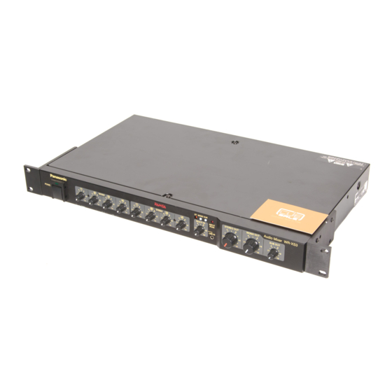
Audio Mixer Operating Instructions WR-XS3 Model No. Before attempting to connect or operate this product, please read these instructions carefully and save this manual for future use. - Page 2 You should note the serial number of this unit in the space provided and retain this book as a permanent record of your purchase to aid identification in the event of theft. Model No. WR-XS3 Serial No. The model numbers in these Operating Instructions are given without suffix.
- Page 3 Model No. WR-XS3 Serial No. WARNING: To reduce the risk of fire or electric shock, do not expose this appliance to rain or moisture.
-
Page 4: Important Safety Instructions
IMPORTANT SAFETY INSTRUCTIONS 1) Read these instructions. 2) Keep these instructions. 3) Heed all warnings. 4) Follow all instructions. 5) Do not use this apparatus near water. 6) Clean only with dry cloth. 7) Do not block any ventilation openings. Install in accordance with the manufacturer's instructions. 8) Do not use near any heat sources such as radiators, heat registers, stoves or other apparatus (including amplifiers) that produce heat. -
Page 5: Table Of Contents
IMPORTANT SAFETY INSTRUCTIONS ...4 PREFACE ...6 FEATURES ...6 PRECAUTIONS ...7 MAJOR OPERATING CONTROLS AND THEIR FUNCTIONS ...8 Front View ...8 Rear View ...9 INSTALLATION ...11 Work Flow ...11 Before Installation ...11 Power Connection ...11 Installation Place ...11 Rack Mounting ...11 Grounding the Unit ...11 Condenser Microphone ...11 Mounting into the Rack ...12... -
Page 6: Preface
PREFACE This audio mixer has four mono input lines, four stereo input lines, one mono/stereo input line and three output lines. FEATURES Three modes applicable to different amplification systems DIP switches at the rear panel support the following amplification systems: •... -
Page 7: Precautions
Use the appliance at temperatures within 0 °C - +45 °C (32 °F - 113 °F) and a humidity below 90 %. The input power source for WR-XS3 is 120 V AC, 60 Hz or 220 - 240 V AC, 50 Hz.* * Power supply is not switchable but conformed to your area. -
Page 8: Major Operating Controls And Their Functions
Input gains are in conjunction with output gains. (Dual- level control) MONO IN –80 to –10dB Note: When using Panasonic wireless microphones, set the output level to –20 dB. r Stereo input level knobs [STEREO 1 to 4] Stereo input levels are adjustable with these knobs cor- responding widely to the connected devices, e.g., from... -
Page 9: Rear View
!0 I nput peak indicator [INPUT PEAK] Lights up when any input signal reaches –3 dB (from the MONO INPUT 1 to 4 connectors, the STEREO INPUT 1 to 4 jacks , the MULTI INPUT ST connectors, the MULTI INPUT MONO connector and the LINE IN jack) above the clip level. - Page 10 Input level: –10 dBV Impedance: 10 k o Multiple mono input connector [MULTI INPUT MONO] Connects a microphone. When using this connector, remove the short pin. Mono: 1 circuit Input connector: XLR-3-31 type balanced Input level: –45 dB Impedance: 10 k !0 Stereo input jacks [STEREO INPUT L/R 1 - 4] These XRL connectors receive input signals from up to 4 audio-visual devices such as a CD player and tape...
-
Page 11: Installation
INSTALLATION Work Flow System Configuration Decide what kind of system to form. Determine the num- ber of the external devices, the connection form, and the mode (p. 14 Unit Modes and Signal Flow). Connections Connect the components to the unit. Settings Configure the following settings: •... -
Page 12: Mounting Into The Rack
Items to prepare If you use a rack supplied by other than Panasonic, it may require four rack mounting screws (option) or four M5 x 12 screws. (If you use a Panasonic rack, you can use the tapping screws supplied with the rack.) Where to install 1. -
Page 13: Cable Information
Cable Information The usable cable types, plugs, and connectors are the following. Before connection, sure you are using the proper cables. Pin plug Tip-ring-sleeve (TRS) phone plug XLR connector (XLR3-12 type) Screw (x3) Spring washer (HOT) (COLD) Caution: No.2 pin of the XLR connector of this unit is hot. When connecting a device whose No.3 is hot, connect No.2 pin (No.3 pin) of this unit to No.3 pin (No. -
Page 14: Setup Procedures
Speakers Power amplifier Digital Multi Equalizer STEREO OUTPUT MULTI IN Internal MIX (MONO/ STEREO) MONO Audio Mixer WR-XS3 STEREO OUT MONO OUT MULTI IN INPUT SUB OUT REAK LINE IN Any mono and stereo input can be assigned to the SUB OUTPUT jack. -
Page 15: Signal Flow
STEREO MULTI IN Ceiling speakers Power amplifier Digital Multi Equalizer MONO OUTPUT Internal MIX Audio Mixer WR-XS3 STEREO OUT MONO OUT INPUT SUB OUT REAK LINE IN Any mono and stereo input can be assigned to the SUB OUTPUT jack. -
Page 16: Mode 2
MULTI IN Speakers Ceiling speakers Power amplifier Digital Multi Equalizer MONO STEREO OUTPUT OUTPUT Audio Mixer WR-XS3 STEREO OUT MONO OUT INPUT SUB OUT REAK LINE IN Any mono and stereo input can be assigned to the SUB OUTPUT jack. -
Page 17: Mode 3
Zone 1. (Switch inside) Speakers Power amplifier Digital Multi Equalizer Zone 1 Zone 2 MONO Audio Mixer WR-XS3 STEREO OUT MONO OUT INPUT SUB OUT MULTI IN REAK LINE IN Any mono and stereo input can be assigned to the SUB... -
Page 18: Input Line Setting For Sub Output
The figure shows an example that assigns the MONO INPUT 3 connector, STEREO INPUT 2 jack, and STEREO INPUT 4 jack to the SUB OUTPUT jack. MONO STEREO MONO Any output can be assigned. Both mono and stereo inputs are available. MONO Audio Mixer WR-XS3 STEREO OUT MONO OUT INPUT SUB OUT MULTI IN REAK LINE IN... -
Page 19: Output Line Setting For Multi In/Line In
STEREO OUT knob. Level 5 to 8 8 to 9 8 to 10 8 to 9 7 to 9 MONO Audio Mixer WR-XS3 STEREO OUT MONO OUT MULTI IN INPUT SUB OUT REAK LINE IN Assign buttons... - Page 20 When using the MULTI INPUT ST jacks (or MONO connector) and LINE IN jack at the same time In this case, the signal from the MULTI INPUT ST jacks will not be output. The signal is mixed inside the unit and output through the assigned output connector. Notes: •...
-
Page 21: Connection Examples
POWER LINE IN Equalizer Power amplifier Power amplifier Foldback loudspeakers Main speakers DVD/CD Bass AMP TAPE(REC) DIP switch setting Audio Mixer WR-XS3 SUB OUT WR-XS3 Unit mode : 1 Sub output: MONO IN 1 to 4 and STEREO 1, 2... -
Page 22: Example 2: Presentation Room (Mode 2)
Antenna for TAPE TAPE(REC) AV switcher MONO IN ST IN 3 to 4 1 to 4 MONO STEREO OUT MONO OUT Audio Mixer WR-XS3 SUB OUT MONO STEREO MULTI IN INPUT WR-XS3 REAK POWER LINE IN LINE IN SUB OUT... -
Page 23: Example 3: Shop (Mode 3)
• All-call amplification is also available in the resting place. Mic 1 or 2 (MONO IN 1 and 2) is output to the main speakers (SUB OUT). Shop 2 microphone ST IN 1 to 4 MONO STEREO OUT MONO OUT Audio Mixer WR-XS3 SUB OUT MONO STEREO MULTI IN INPUT REAK POWER LINE IN... -
Page 24: Recorder Connections
RECORDER CONNECTIONS When you connect a cassette tape recorder or MD recorder to record the broadcasting, confirm the following: Notice about Recorder Connections Howling can occur depending on the connection form or connected devices. Connect the recording devices either of the fol- lowing ways: When Using a Recording-only and a Playback-only Decks... -
Page 25: Recording And Playback With One Deck
Recording and Playback with One Deck To record and play back a broadcast with one deck, connect the SUB OUTPUT jack to cut the feedback. Then set the DIP switch associated with the MULTI INPUT ST jacks to OFF. MODE 4 3 2 1 4 3 2 1 STEREO MONO INPUT... -
Page 26: Sticking Labels
SUB OUT STEREO 2 3 4 M O N O MONO STEREO For STEREO INPUT label Marker for volume setting label MONO Audio Mixer WR-XS3 STEREO OUT MONO OUT INPUT SUB OUT MULTI IN REAK LINE IN For OUTPUT label... -
Page 27: Indication Of Input Line Assigned To Sub Out
Indication of Input Line Assigned to SUB OUT Draw a line between SUB OUT and the assigned input connector, or black out the square. The assigned input line will be identifiable. Draw a line or black out to identify the assigned input line. -
Page 28: Attaching/Detaching The Acrylic Cover
2 Acrylic cover MONO STEREO OUT MONO OUT STEREO MULTI IN INPUT REAK LINE IN MONO STEREO OUT MONO OUT STEREO MULTI IN INPUT REAK LINE IN Audio Mixer WR-XS3 SUB OUT Audio Mixer WR-XS3 SUB OUT... -
Page 29: Operations
• When one of the STEREO INPUT 1 to 4 jacks or MONO INPUT 1 to 4 connectors is assigned to the SUB OUTPUT jack, the output level is adjustable with the SUB OUT knob. MONO STEREO MONO STEREO MONO Audio Mixer WR-XS3 STEREO OUT MONO OUT MULTI IN INPUT SUB OUT REAK... -
Page 30: Input Level Adjustment
Note: Detach the acrylic cover before the level adjustment. (Refer to p. 28 ATTACHING/DETACHING THE ACRYLIC COVER.) 1. Decrease the attenuator level to . 2. Increase the level of the STEREO OUT and MONO OUT knobs to 7. MONO Audio Mixer WR-XS3 STEREO OUT MONO OUT INPUT MULTI IN... -
Page 31: Using Cd/Md Player Through Line In
This section describes amplification when a CD player or MD player, etc. is connected to the LINE IN jack at the front panel. 1. Set the LINE IN jack's output level knob to 0. MONO Audio Mixer WR-XS3 STEREO OUT MONO OUT MULTI IN INPUT... -
Page 32: Block Diagram
MONO 1 MONO 2 MONO 3 MONO 4 ST 1 ST 2 ST 3 ST 4 MULTI IN MULTI IN MONO MONO Inner SW MULTI IN LINE IN (FRONT PANEL) SUB IN MIXING POINT Electric Switch STEREO MONO SUB MUTE SENSE REAR PANEL SW SENS Mute... - Page 33 MONO 1 MONO 2 MONO 3 MONO 4 ST 1 ST 2 ST 3 ST 4 MULTI IN MULTI IN MONO MONO Inner SW MULTI IN LINE IN (FRONT PANEL) SUB IN MIXING POINT Electric Switch STEREO MONO SUB MUTE SENSE REAR PANEL SW SENS Mute...
- Page 34 MONO 1 MONO 2 MONO 3 MONO 4 ST 1 ST 2 ST 3 ST 4 MULTI IN MULTI IN MONO MONO Inner SW MULTI IN LINE IN (FRONT PANEL) SUB IN MIXING POINT Electric Switch STEREO MONO SUB MUTE SENSE REAR PANEL SW SENS Mute...
-
Page 35: Mode 3
MONO 1 MONO 2 MUTE SENSE REAR PANEL SW MONO 3 MONO 4 ST 1 ST 2 ST 3 ST 4 MULTI IN MULTI IN MONO MONO Inner SW MULTI IN LINE IN (FRONT PANEL) SUB IN MIXING POINT Electric Switch STEREO MONO SUB SENS Mute... -
Page 36: Level Diagram
(+38.9 to +2.4 to –3.6) (+9.6) (+11.9) MONO IN –60 dBu to –10 dBu (+27.6) (+9.6) MULTI IN –45 dBu (+8.2) –10 dBV (–7.8 dBu) (+8.2) ST IN –10 dBV (–7.8 dBu) SUB IN +4 dBu (dBu) CLIP LEVEL ST "10" –10 MONO "2"... -
Page 37: Troubleshooting
TROUBLESHOOTING Check to see the following before request for repair. If a trouble can not be removed even after checking and trying remedy, contact your dealer. Trouble Power does not turn on. No sound is heard from the speakers connected to SUB OUTPUT. -
Page 38: Specifications
SPECIFICATIONS Basic Specifications Power supply Power consumption Temperature range Dimensions Weight Frequency response High-pass filter Total harmonic distortion Input conversion noise Residual noise Maximum input Maximum output Crosstalk Common mode rejection ratio Maximum voltage gain Input Circuit Mono inputs 1 to 4 Stereo inputs 1 to 4 Multi input (mono) Multi input (stereo) - Page 39 (For U.S.A. and Canada) Panasonic Security and Digital Imaging Company A Division of Matsushita Electric Corporation of America Executive Office: One Panasonic Way 3E-7, Secaucus, New Jersey 07094 Regional Offices: Northeast: One Panasonic Way, Secaucus, NJ 07094 (201) 348-7303 Southern: 1225 Northbrook Parkway, Suite 1-160, Suwanee, GA 30024 (770) 338-6838...