Table of Contents
Advertisement
Quick Links
Advertisement
Table of Contents

Related Manuals for Bosch PAVIRO PVA-2P500


Summary of Contents for Bosch PAVIRO PVA-2P500
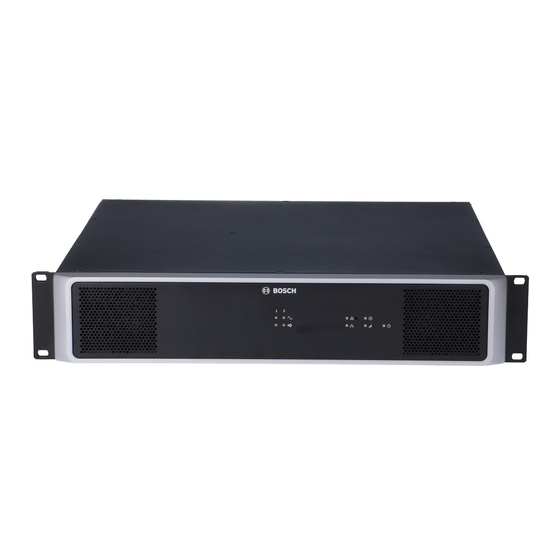
- Page 1 PAVIRO Amplifier PVA‑2P500 User manual...
-
Page 3: Table Of Contents
Displaying the CAN baud rate Configuring the CAN baud rate Operation Stand-alone mode Maintenance Firmware update Resetting to factory default settings Technical data 10.1 Power consumption 10.2 Dimensions 10.3 Circuit diagram Bosch Security Systems, B.V. 2023-03 | 08 | F01U306898 User manual... -
Page 4: Important Product Information
European Waste Electrical and Electronic Equipment Directive). To dispose of old electrical or electronic devices, you should use the return and collection systems put in place in the country concerned. FCC statement 2023-03 | 08 | F01U306898 Bosch Security Systems, B.V. User manual... - Page 5 PAVIRO Amplifier Important product information | en Warning! Changes or modifications not expressly approved by Bosch could void the user’s authority to operate the equipment. Notice! This equipment has been tested and found to comply with the limits for a Class B digital device, pursuant to Part 15 of the FCC Rules.
-
Page 6: Short Information
The power amplifier is processor-controlled and equipped with extensive monitoring functions. Line monitoring for the CAN bus and for audio transmission allows line interruptions and short-circuits to be detected and indicated to the user. 2023-03 | 08 | F01U306898 Bosch Security Systems, B.V. User manual... -
Page 7: System Overview
This button has the following functions if the CAN address of the device is set to 00 (stand-alone mode): Bosch Security Systems, B.V. 2023-03 | 08 | F01U306898 User manual... - Page 8 Standby indicator This indicator lights up green when the device is in light standby mode. Power indicator This indicator lights up green when the power light supply is OK. 2023-03 | 08 | F01U306898 Bosch Security Systems, B.V. User manual...
-
Page 9: Rear Panel
Audio inputs, page 13 . sockets (Euroblock) Amplifier power output Power output for speaker zones. Please refer to section Audio output, page 15 . sockets (70 V or 100 V) Bosch Security Systems, B.V. 2023-03 | 08 | F01U306898 User manual... -
Page 10: Parts Included
PAVIRO Amplifier Parts included Quantity Component PVA-2P500 Power Amplifier Power cord 230 V AC Power cord 120 V AC Set of connectors Set of feet Installation manual Important safety instructions 2023-03 | 08 | F01U306898 Bosch Security Systems, B.V. User manual... -
Page 11: Installation
Please refer to the technical specifications provided by the rack rail manufacturer. Figure 5.2: Stacking of devices using the supplied foot stands (example with 3 devices, rack mount rails are used for the bottom device only) Bosch Security Systems, B.V. 2023-03 | 08 | F01U306898 User manual... - Page 12 The P column lists the power dissipation for various loss operating conditions. 2023-03 | 08 | F01U306898 Bosch Security Systems, B.V. User manual...
-
Page 13: Connection
Do not use Ethernet crossover cables to connect audio inputs. Only use high quality straight through Ethernet cables with shielding. Notice! Do not plug a CAN terminating resistor into the LINE IN 1-4 socket. Euroblock Bosch Security Systems, B.V. 2023-03 | 08 | F01U306898 User manual... - Page 14 (see diagram below), otherwise the level can drop by 6 dB. However, for reasons of immunity to external interference sources such as dimmers, mains supplies, HF control lines etc., balanced cabling is always preferable. Figure 6.3: Unbalanced cabling 2023-03 | 08 | F01U306898 Bosch Security Systems, B.V. User manual...
-
Page 15: Audio Output
Notice! If the AC and DC power inputs are used, it is recommended to connect AC power first, then switch on the device, then connect the DC power source. Bosch Security Systems, B.V. 2023-03 | 08 | F01U306898 User manual... - Page 16 3 dB if DC is connected only. Notice! The DC input cannot be switched off. The power switch can only be used to switch off the mains power supply. 2023-03 | 08 | F01U306898 Bosch Security Systems, B.V. User manual...
-
Page 17: Can Bus
Table 6.1: Data rate and bus length of the CAN BUS The following diagrams show the assignment of the CAN port/CAN connector. Figure 6.4: Assignment of the CAN port Figure 6.5: Assignment of the CAN connector Bosch Security Systems, B.V. 2023-03 | 08 | F01U306898 User manual... - Page 18 Since there must always be precisely two terminating resistors on a CAN bus, a stub line cannot be terminated. This creates reflections, which impair the rest of the bus system. To 2023-03 | 08 | F01U306898 Bosch Security Systems, B.V. User manual...
- Page 19 The guidelines specified above for the network cabling must be used when wiring the racks with each other and for the building installation. Refer to – Configuring the CAN baud rate, page 21 Bosch Security Systems, B.V. 2023-03 | 08 | F01U306898 User manual...
-
Page 20: Configuration
0 to F 192 to 207 0 to F 208 to 223 0 to F 224 to 239 0 to A 240 to 250 B to F Reserved Table 7.5: CAN addresses 2023-03 | 08 | F01U306898 Bosch Security Systems, B.V. User manual... -
Page 21: Displaying The Can Baud Rate
62.5 kbit/s to 20 kbit/s, press the Recessed button exactly five times, i.e. 62.5 > 125 > 250 > 500 > 10 > 20). The new CAN baud rate is applied two seconds after the last time that the Recessed button is pressed. Bosch Security Systems, B.V. 2023-03 | 08 | F01U306898 User manual... -
Page 22: Operation
Ground fault indicator light must light. If the resistance is greater than 100 kOhms and the 2023-03 | 08 | F01U306898 Bosch Security Systems, B.V. User manual... - Page 23 5 μF, the Ground fault indicator light must not light up. After the resistor has been removed, the display and the malfunction message must continue to be shown. To reset the ground fault monitoring function, press the Recessed button. Bosch Security Systems, B.V. 2023-03 | 08 | F01U306898 User manual...
-
Page 24: Maintenance
The device has now been reset to the factory default settings. Caution! Before reconnecting the device to the CAN BUS, note the CAN baud rate, which may change under certain circumstances. 2023-03 | 08 | F01U306898 Bosch Security Systems, B.V. User manual... -
Page 25: Technical Data
* Alarm, ** No audio (pilot tone) Inrush current Inrush current, after five-second power cycle 1.3 A Mains fuse T6.3A (internally) DC fuse 30A (internally) Ground fault R < 50 kΩ Bosch Security Systems, B.V. 2023-03 | 08 | F01U306898 User manual... - Page 26 Humidity (non-condensing) 5% to 90% Altitude Up to 2000 m Mechanical Dimensions (HxWxD) 88 mm x 483 mm x 375 mm (2RU) Weight (net) 16.5 kg Mounting Standalone; 19 in. rack Color Black with silver 2023-03 | 08 | F01U306898 Bosch Security Systems, B.V. User manual...
-
Page 27: Power Consumption
– = reactive power drawn from mains (or DC supply) supply – = NF output power provided to the speaker lines – or BTU/h = thermal loss loss Bosch Security Systems, B.V. 2023-03 | 08 | F01U306898 User manual... -
Page 28: Dimensions
| Technical data PAVIRO Amplifier 10.2 Dimensions 2023-03 | 08 | F01U306898 Bosch Security Systems, B.V. User manual... -
Page 29: Circuit Diagram
PAVIRO Amplifier Technical data | en 10.3 Circuit diagram Bosch Security Systems, B.V. 2023-03 | 08 | F01U306898 User manual... - Page 30 | Technical data PAVIRO Amplifier 2023-03 | 08 | F01U306898 Bosch Security Systems, B.V. User manual...
- Page 32 Bosch Security Systems B.V. Torenallee 49 5617 BA Eindhoven Netherlands www.boschsecurity.com © Bosch Security Systems B.V., 2023 Building solutions for a better life. 202303090917...