Siemens SIMATIC NET S7-1200 Operating Instructions Manual
Hide thumbs
Also See for SIMATIC NET S7-1200:
- Operating instructions manual (74 pages) ,
- Operating instructions manual (98 pages) ,
- Compact operating instructions (50 pages)
Table of Contents
Advertisement
Quick Links
SIMATIC CM 1243-5
SIMATIC NET
S7-1200 - PROFIBUS
SIMATIC CM 1243-5
Operating Instructions
01/2023
C79000-G8976-C246-06
Preface
Application and properties
LEDs and connectors
Installation, connecting up,
commissioning
Configuration and program
blocks
Diagnostics and upkeep
Technical specifications
Dimension drawings
Approvals
References
1
2
3
4
5
6
A
B
C
Advertisement
Table of Contents

Related Manuals for Siemens SIMATIC NET S7-1200


Summary of Contents for Siemens SIMATIC NET S7-1200
- Page 1 SIMATIC CM 1243-5 Preface Application and properties SIMATIC NET LEDs and connectors Installation, connecting up, commissioning S7-1200 - PROFIBUS SIMATIC CM 1243-5 Configuration and program blocks Diagnostics and upkeep Operating Instructions Technical specifications Dimension drawings Approvals References 01/2023 C79000-G8976-C246-06...
- Page 2 Note the following: WARNING Siemens products may only be used for the applications described in the catalog and in the relevant technical documentation. If products and components from other manufacturers are used, these must be recommended or approved by Siemens. Proper transport, storage, installation, assembly, commissioning, operation and maintenance are required to ensure that the products operate safely and without any problems.
-
Page 3: Preface
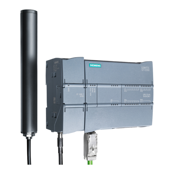
Preface Validity of this manual This document contains information on the following product: CM 1243-5 Article number 6GK7 243-5DX30-0XE0 Hardware version 3 Firmware version V1.3.8 Communications module for connection of the SIMATIC S7-1200 to PROFIBUS (DP master module) Communications module for the PROFIBUS DP master function for the SIMATIC S7-1200. Figure 1 CM 1243-5 At the top right behind the hinged cover of the module housing, you will see the hardware... - Page 4 • Editorial revision Replaced manual edition Edition 06/2017 Current manual edition on the Internet You can find the current version of this manual on the Internet pages of Siemens Industry Online Support: Link: (https://support.industry.siemens.com/cs/ww/en/view/49851842) Purpose of the manual This manual describes the properties of this module and supports you when installing and commissioning the device.
- Page 5 Siemens’ products and solutions undergo continuous development to make them more secure. Siemens strongly recommends that product updates are applied as soon as they are available and that the latest product versions are used. Use of product versions that are no longer supported, and failure to apply the latest updates may increase customers’...
- Page 6 Device defective If a fault develops, please send the device to your Siemens representative for repair. Repairs on-site are not possible. Decommissioning Shut down the device properly to prevent unauthorized persons from accessing confidential data in the device memory.
- Page 7 Preface SIMATIC NET glossary The SIMATIC NET glossary describes terms that may be used in this document. You will find the SIMATIC NET glossary in the Siemens Industry Online Support at the following address: Link: (https://support.industry.siemens.com/cs/ww/en/view/50305045) Training, Service & Support You will find information on Training, Service &...
- Page 8 Preface SIMATIC CM 1243-5 Operating Instructions, 01/2023, C79000-G8976-C246-06...
-
Page 9: Table Of Contents
Table of contents Preface ..............................3 Application and properties ........................11 Connecting the S7-1200 to PROFIBUS ................11 Communications services of the CM ................... 11 Performance data ......................13 Requirements for operation ....................15 Configuration examples for PROFIBUS ................16 LEDs and connectors .......................... - Page 10 Table of contents Approvals ............................. 47 References ............................53 Index ..............................55 SIMATIC CM 1243-5 Operating Instructions, 01/2023, C79000-G8976-C246-06...
-
Page 11: Application And Properties
Application and properties Connecting the S7-1200 to PROFIBUS Connecting the S7-1200 to PROFIBUS DP The S7-1200 can be connected to a PROFIBUS fieldbus system with the following communications modules: • CM 1242-5 Operates as DP slave • CM 1243-5 Operates as DP master class 1 If a CM 1242-5 and a CM 1243-5 are installed together, an S7-1200 can perform the following tasks simultaneously: •... - Page 12 Application and properties 1.2 Communications services of the CM • S7-300/400 with PROFIBUS CP (for example CP 342-5) • SIMATIC PC stations with PROFIBUS CP Types of communication with the CM 1243-5 in DP-V1 The following types of communication are available with DP-V1: •...
-
Page 13: Performance Data
Application and properties 1.3 Performance data Performance data Number of CPs/CMs that can be plugged in per S7-1200 station You can configure a maximum of three CMs/CPs per station. The maximum number of DP master modules depends on the firmware version of the CPU in the master station: •... - Page 14 Application and properties 1.3 Performance data • Data areas of the DP master Size of the DP data areas of the DP master: Max. 1024 bytes – Input area of the DP master in total: Max. 512 bytes – Output area of the DP master in total: Max. 512 bytes •...
-
Page 15: Requirements For Operation
Application and properties 1.4 Requirements for operation Requirements for operation Configuration tool To configure the module, the following configuration tool is required: • STEP 7 Basic For the precise version, refer to the following table. CPUs of the S7-1200 Use of PROFIBUS functionalities with the S7-1200 requires CPUs with firmware versions 2.0 or higher in the master station. -
Page 16: Configuration Examples For Profibus
Application and properties 1.5 Configuration examples for PROFIBUS Configuration examples for PROFIBUS Below, you will find examples of configurations in which the CM 1242-5 is used as a DP slave and the CM 1243-5 is used as a DP master. Figure 1-1 Configuration example with a CM 1242-5 as PROFIBUS slave Figure 1-2... -
Page 17: Leds And Connectors
LEDs and connectors Opening the covers of the housing Location of the display elements and the electrical connectors The LEDs for the detailed display of the module statuses are located behind the upper cover of the module housing. The terminals for the power supply are located on the top of the module. The PROFIBUS connector is located behind the lower cover of the module. -
Page 18: Leds
LEDs and connectors 2.2 LEDs LEDs LEDs of the module The module has various LEDs for displaying the status: • LED on the front panel The "DIAG" LED that is always visible shows the basic statuses of the module. Table 2- 1 LED on the front panel LED / colors Name... - Page 19 LEDs and connectors 2.2 LEDs The LEDs indicate the operating and communications status of the module according to the following scheme: Table 2- 4 Display of the basic states of the module by the "DIAG" LED DIAG Meaning Comment (red / green) Power OFF RUN without errors green...
- Page 20 LEDs and connectors 2.2 LEDs Table 2- 5 Display schemes for detailed module statuses DIAG RUN/STOP ERROR Meaning (red / green) (yellow / (red) green) Detailed status schemes RUN without errors, Exchange of user data with DP master green • Stopped (STOP) without errors •...
-
Page 21: Electrical Connections
LEDs and connectors 2.3 Electrical connections Electrical connections Power supply The 3-pin socket for the external 24 V DC power supply is located on the top of the module. The matching plug ships with the product. You will find the pin assignment of the socket in section Pin assignment of the socket for the external power supply (Page 42). - Page 22 LEDs and connectors 2.3 Electrical connections SIMATIC CM 1243-5 Operating Instructions, 01/2023, C79000-G8976-C246-06...
-
Page 23: Installation, Connecting Up, Commissioning
Installation, connecting up, commissioning Safety notices on the use of the device Note the following safety notices when setting up and operating the device and during all associated work such as installation, connecting up or replacing the device. Important notes on using the device 3.1.1 Notes on use in hazardous areas WARNING... -
Page 24: Notes On Use In Hazardous Areas According To Ul Hazloc And Fm
Installation, connecting up, commissioning 3.1 Important notes on using the device WARNING Suitable cables at high ambient temperatures in hazardous area Use heat-resistant cables with an ambient temperature ≥ 60 °C; these cables must be rated for an ambient temperature that is at least 20 °C higher. The cable entries used on the housing must comply with the IP degree of protection required by EN IEC 60079-0 / GB 3836.1. -
Page 25: Installation, Removal And Repairs In Hazardous Areas
Installation, connecting up, commissioning 3.2 Installation, removal and repairs in hazardous areas Installation, removal and repairs in hazardous areas WARNING Impermissible accessories and spare parts Risk of explosion in hazardous areas • Only use original accessories and original spare parts. •... -
Page 26: Installing, Connecting And Commissioning
• Observe the device approvals applicable for your country. WARNING Unauthorized repair of devices in explosion-proof design Risk of explosion in hazardous areas • Repair work may only be performed by personnel authorized by Siemens. Installing, connecting and commissioning NOTICE Improper mounting Improper mounting may damage the device or impair its operation. - Page 27 Installation, connecting up, commissioning 3.3 Installing, connecting and commissioning WARNING Power supply The device is designed for operation with a directly connectable safety extra low voltage (SELV) from a limited power source (LPS). The power supply therefore needs to meet at least one of the following conditions: •...
- Page 28 Installation, connecting up, commissioning 3.3 Installing, connecting and commissioning Dimensions for installation Figure 3-1 Dimensions for installation of the S7-1200 Table 3- 1 Dimensions for installation S7-1200 devices Width A Width B * CPU 1211C, CPU 1212C 90 mm 45 mm CPU 1214C 110 mm 55 mm...
- Page 29 Installation, connecting up, commissioning 3.3 Installing, connecting and commissioning Procedure for installation and commissioning Note Installation location During installation, make sure that the upper and lower ventilation slits of the module are not obstructed and good ventilation is possible. Above and below the device, there must be a clearance of 25 mm to allow air to circulate and prevent overheating.
-
Page 30: Note On Operation
Installation, connecting up, commissioning 3.4 Note on operation Table 3- 2 Procedure for installation and connecting up Step Execution Notes and explanations Mount the CM on the DIN rail and connect it to Use a 35 mm DIN rail. the module to its right. The slots to the left of the CPU are permitted. -
Page 31: Disassembly
Installation, connecting up, commissioning 3.5 Disassembly Disassembly WARNING Improper disassembly Improper disassembly may result in a risk of explosion in hazardous areas. For proper disassembly, observe the following: • Before starting work, ensure that the electricity is switched off. • Secure remaining connections so that no damage can occur as a result of disassembly if the system is accidentally started up. - Page 32 Installation, connecting up, commissioning 3.5 Disassembly SIMATIC CM 1243-5 Operating Instructions, 01/2023, C79000-G8976-C246-06...
-
Page 33: Configuration And Program Blocks
Configuration and program blocks Configuration Configuration in STEP 7 You configure the DP modules and DP master systems in SIMATIC STEP 7. You will find the required version in the section Requirements for operation (Page 15). You will find the number of CMs/CPs that can be configured per station in the section Performance data (Page 13). -
Page 34: Program Blocks
Configuration and program blocks 4.2 Program blocks 9. Configure the remaining modules and submodules according to your requirements. 10. Save the project. Note You will find more detailed information on configuring the individual parameters in the help system of STEP 7. Downloading project data When you load the station, the project data of the CM is stored on the CPU. - Page 35 Configuration and program blocks 4.2 Program blocks Remote communications partners can be S7-CPUs, PCs, PGs, TDs/OPs or SCADA systems, such as WinCC. Note Information on the instructions You will find information on the instructions mentioned above in the STEP 7 help. SIMATIC CM 1243-5 Operating Instructions, 01/2023, C79000-G8976-C246-06...
- Page 36 Configuration and program blocks 4.2 Program blocks SIMATIC CM 1243-5 Operating Instructions, 01/2023, C79000-G8976-C246-06...
-
Page 37: Diagnostics And Upkeep
Diagnostics and upkeep Diagnostics Diagnostics options You have the following diagnostics options available for the module: • The LEDs of the module For information on the LED displays, refer to the section LEDs (Page 18). • STEP 7: The "Diagnostics" tab in the Inspector window Here, you can obtain the following information on the selected module: –... -
Page 38: Maintenance
Do not use any liquids or solvents. WARNING Unauthorized repair of devices in explosion-proof design Risk of explosion in hazardous areas • Repair work may only be performed by personnel authorized by Siemens. 5.2.1 Downloading firmware New firmware versions If a new firmware version is available for the module, you will find this on the Internet pages of Siemens Industry Online Support: Link: (https://support.industry.siemens.com/cs/ww/en/ps/15669/dl) -
Page 39: Module Replacement
To load a firmware file you require a SIMATIC memory card. You will find a description of the procedure for loading firmware on the respective page of Siemens Industry Online Support. You can recognize that firmware is being loaded by the flashing LEDs of the CM, see section LEDs (Page 18). - Page 40 Diagnostics and upkeep 5.2 Maintenance SIMATIC CM 1243-5 Operating Instructions, 01/2023, C79000-G8976-C246-06...
-
Page 41: Technical Specifications
Technical specifications Technical specifications of the CM 1243-5 Table 6- 1 Technical specifications of the CM 1243-5 Technical specifications Article number 6GK7 243-5DX30-0XE0 Interfaces Connection to PROFIBUS 9-pin D-sub female connector Maximum current consumption on the PROFIBUS interface 15 mA at 5 V (only for bus termination) * when connecting network components (for example optical network components) Permitted ambient conditions... -
Page 42: Pin Assignment Of The Socket For The External Power Supply
Technical specifications 6.2 Pin assignment of the socket for the external power supply Technical specifications Electrical isolation 710 VDC for 1 minute • PROFIBUS interface to ground • PROFIBUS interface to internal circuit Dimensions and weights • Width • 30 mm •... -
Page 43: Pinout Of The D-Sub Socket
Technical specifications 6.3 Pinout of the D-sub socket Pinout of the D-sub socket PROFIBUS interface Table 6- 3 Pinout of the D-sub socket Description Description - not used - VP: Power supply +5 V only for bus terminating resistors; not for supplying external devices - not used - - not used - RxD/TxD-P: Data line B... - Page 44 Technical specifications 6.3 Pinout of the D-sub socket SIMATIC CM 1243-5 Operating Instructions, 01/2023, C79000-G8976-C246-06...
-
Page 45: Dimension Drawings
Dimension drawings Note All dimensions in the drawings are in millimeters. Figure A-1 CM 1243-5 - front view SIMATIC CM 1243-5 Operating Instructions, 01/2023, C79000-G8976-C246-06... - Page 46 Dimension drawings Figure A-2 CM 1243-5 - left side view Figure A-3 CM 1243-5 - view from above SIMATIC CM 1243-5 Operating Instructions, 01/2023, C79000-G8976-C246-06...
- Page 47 The approvals for shipbuilding are an exception to this. Certificates for shipbuilding and national approvals The device certificates for shipbuilding and special national approvals can be found in Siemens Industry Online Support on the Internet: Link: (https://support.industry.siemens.com/cs/ww/en/ps/15669/cert) Documents on the Internet...
- Page 48 Directive of the European Parliament and of the Council of 8 June 2011 on the restriction of the use of certain hazardous substances in electrical and electronic equipment UK Declaration of Conformity Importer UK: Siemens plc Sir William Siemens House Princess Road Manchester M20 2UR The product meets the requirements of the following directives: •...
- Page 49 • EN IEC 60079-0 - Explosive atmospheres - Part 0: Equipment - General requirements • EN 60079-7 - Explosive Atmospheres - Part 7: Equipment protection by increased safety 'e' Importer UK: Siemens plc (see above) SIMATIC CM 1243-5 Operating Instructions, 01/2023, C79000-G8976-C246-06...
- Page 50 Approvals CCC-Ex Classification:Ex na IIC T4 Gc (not on the type plate), Certificate no.:2020322310002625 The product meets the requirements of the following standards: • GB 3836.1 Hazardous areas - Part 0: Equipment - General requirements • GB 3836.3 Explosive atmospheres - Part 3: Equipment protection by increased safety "e" •...
- Page 51 Approvals cULus Hazardous (Classified) Locations Underwriters Laboratories, Inc.: cULus IND. CONT. EQ. FOR HAZ. LOC. Applied standards: • ANSI ISA 12.12.01 • CSA C22.2 No. 213-M1987 APPROVED for Use in: • Cl. 1, Div. 2, GP. A, B, C, D T4A; Ta = -20 °C...60 °C •...
- Page 52 SIMATIC NET products are regularly submitted to the relevant authorities and approval centers for approvals relating to specific markets and applications. If you require a list of the current approvals for individual devices, consult your Siemens contact or check the Internet pages of Siemens Industry Online Support: Link: (https://support.industry.siemens.com/cs/ww/en/ps/15669/cert)
- Page 53 References Where to find Siemens documentation • Article numbers You will find the article numbers for the Siemens products of relevance here in the following catalogs: – SIMATIC NET - Industrial Communication / Industrial Identification, catalog IK PI – SIMATIC - Products for Totally Integrated Automation and Micro Automation, catalog...
- Page 54 References SIMATIC NET PROFIBUS Network Manual system manual Siemens AG Link: (https://support.industry.siemens.com/cs/ww/en/view/35222591) SIMATIC NET CM 1242-5 Operating Instructions Siemens AG Link: (https://support.industry.siemens.com/cs/ww/en/ps/15667/man) SIMATIC CM 1243-5 Operating Instructions, 01/2023, C79000-G8976-C246-06...
- Page 55 Index Article number, 3 Safety notices, 23 Security, 3 Service & Support, 7 SIMATIC NET glossary, 7 STEP 7 version, 15 Configuration limits, 13 SYNC / FREEZE, 12 CPU firmware version, 15 Cross-references (PDF), 4 Training, 7 Dimensions, 28, 42 Disposal, 6 Downloading project data, 30, 34 Uninstalling, 31...