
Related Manuals for Electrolux 535126


Summary of Contents for Electrolux 535126
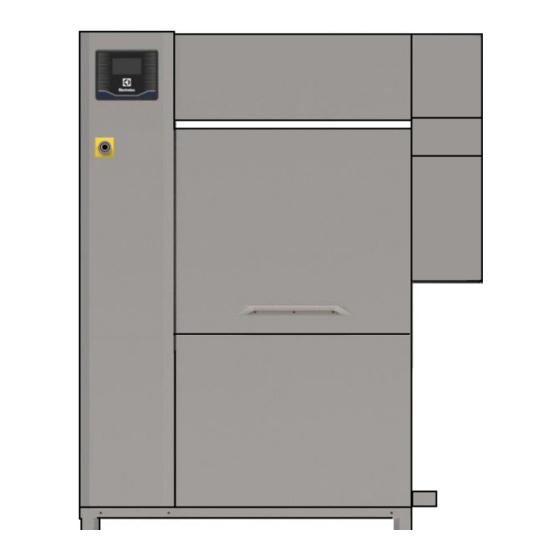
- Page 1 Rack type dishwasher Dual-Rinse Installation manual * 59566TR00- 2020.10 *Original instructions...
- Page 2 Installation diagram 44″...
- Page 3 Installation diagram 66″ right to left...
- Page 4 Installation diagram 66″ left to right...
- Page 5 D = Drain outlet ⌀=50 mm (external) XI= Pipe inlet for delime EI = Electricity inlet XP= Chemicals probe/sensor EO = Electricity outlet HWI = Hot water inlet G 3/4″ ES = Electrical signal IN/OUT CWI = Cold water inlet G 3/4″ EQ = Equipotential screw U = USB XD= Pipe inlet for detergent...
- Page 6 Foreword The installation, use and maintenance manual (hereinafter Manual) provides the user with information necessary for correct and safe use of the machine (or “appliance“). The following must not be considered a long and exacting list of warnings, but rather a set of instructions suitable for improving machine performance in every respect and, above all, preventing injury to persons and animals and damage to property due to im- proper operating procedures.
-
Page 7: Table Of Contents
Arrangement for mechanical connection (only for Electrolux rack handling system non motor operated) ..........................20 E.12 Arrangement for electrical connection (only for Electrolux rack handling system motor operated) ....21 E.13 Installation of the end limit switch ....................21 E.13.1 Prearrangement for electrical connection ................21 E.14... - Page 8 Positioning and fitting of the washing and rinse arms ................27 Positioning and fitting of the curtains ....................28 First starting ..........................28 H BASIC MACHINE SETUP ........................28 Installation wizard ........................28 Enter into service menu ....................... 28 User Interface settings menu......................29 Installation settings menu ......................
-
Page 9: Asafety Information
SAFETY INFORMATION General information To ensure safe use of the machine and a proper understanding of the manual it is necessary to be familiar with the terms and typographical conventions used in the documentation. The following symbols are used in the manual to indicate and identify the various types of hazards: WARNING Danger for the health and safety of operators. -
Page 10: Personal Protection Equipment
• Machine positioning, installation and disassembly must be carried out by the specialised personnel in conformity with the current safety regulations, regarding the equipment used and the operating procedures. Personal protection equipment Summary table of the Personal Protection Equipment (PPE) to be used during the various stages of the machine's service life. -
Page 11: Installation And Assembly
• Do not push or pull the machine to move it, as it may tip over. Use proper tool to lift the machine. • Machine transport, handling and storage personnel must be adequately instructed and trained regarding the use of lifting systems and personal protection equipment suitable for the type of operation carried out. -
Page 12: Machine Cleaning And Maintenance
• To protect the power supply of the machine against current leakages, install a high- sensitivity manual reset RCD (Residual Current Device), suitable for overvoltage category III. • For protection against indirect contacts (depending on the type of supply provided for and connection of earths to the equipotential protection circuit ) refer to point 6.3.3 of EN 60204-1 (IEC 60204-1) with the use of protection devices that ensure automatic cut-... -
Page 13: Service
IPX5 Danger source of possible injury or harm to health. Electrolux Professional spa - Viale Treviso, 15 - 33170 Pordenone (Italy) Hazardous any situation where an operator is situation exposed to one or more hazards. -
Page 14: Additional Indications
50 Hz Other functions W = WRAS - Watermark IPX5 certificate Electrolux Professional spa - Viale Treviso, 15 - 33170 Pordenone (Italy) H = high power M = marine version 440V 3~ Functional level Blank = no ventless ESD (Energy Saving Device) -
Page 15: Responsibility
This manual is intended solely for consultation by the operator The Manufacturer declines any liability for damage and and can only be given to third parties with the permission of malfunctioning caused by: Electrolux Professional company. • non-compliance with the instructions contained in this manual; Keeping the manual •... -
Page 16: Characteristics Of Power Supply
Machine (cont'd.) Model 44″ - 150 racks/hour 66″ - 200 racks/hour Rinse pressure bar [kPa] 1.2 [120] 1.2 [120] Pressure reducer calibration Max. power absorbed Legal noise level Leq dB(A) LpA:58dB - KpA:1.5dB LpA:58dB - KpA:1.5dB The noise emission values have been obtained according to EN ISO 11204. Prewash Model Prewash medium 22″... -
Page 17: Shifting
CAUTION For correct and safe lifting operations: Do not make modifications to the parts • use the type of equipment most suitable for characteristics supplied with the appliance. Any missing and capacity (e.g. electric pallet truck or lift truck); or faulty parts must be replaced with •... -
Page 18: Extraction Hood
The machine must be taken to the place of installation and the packing base removed only when being installed. 300 mm 50 mm Arranging the machine: • Position the machine in the required place. • Adjust the equipment by turning the special adjustable feet. To facilitate the perfect drainage of the water during the drain cycle, adjust the machine with a minimum inclination of 3°... -
Page 19: Disposal Of Packing
Plumbing connections IMPORTANT Watermark labelled appliances must be installed in accordance with AS/NZS 3500.1 and drainage to be in accordance with 3500.2. Install the machine water inlets and drain pipes according to the plumbing circuit and installation diagrams. A booster pump must be installed ahead of the machine, if: •... -
Page 20: Constructional Modifications
1. Remove the vent(s) from the machine, if present. You can see 2 holes in the left and 2 holes in right side of the machine panels. It is available for this purpose recommended silicone by Electrolux. You can order it with this reference code 059611. -
Page 21: Arrangement For Electrical Connection (Only For Electrolux Rack Handling System Motor Operated)
XT2 - 1BEL This arrangement is suitable for fitting motor-operated rack handling systems (e.g. rope conveyor belts). To install the motor-operated rack handling systems, consult the instructions provided with the Electrolux rack handling system. CAUTION CAUTION Make sure to install the end limit switch The electrical power lines of the rack properly. -
Page 22: Electrical Connection
NOTE! To obtain excellence washing performance, use detergent, rinse aid and descaling agent sug- gested by Electrolux Professional. In the Electrolux Professional web site, open the “Accessories and Consumables“ web page and navigate into the dishwashing equipment tab to order most suitable... -
Page 23: Rinse Aid Dispenser
E.16.1 Rinse aid dispenser The left or right side panels of the dishwasher have a “T“ injector [⌀=6 mm] for connecting the rinse aid dispenser. To connect the dispenser, carefully carry out the following instructions: • unscrewing the “U“ fitting from the “T“ injector; •... -
Page 24: Liquid Detergent Dispenser
XT2 - 15 [L1] XT2–13BEL DETERGENT START SIGNAL (230Vac - max 2A) XT2–13AB XT2–14BEL RINSE AID START SIGNAL (230Vac - max 2A) XT2–14AB XT2–15 [L1] EXTERNAL DISPENSER POWER SUPPLY (230Vac - max 5A) XT2–16 [N] E.17.1 Liquid detergent dispenser • Connect the dispenser between terminals XT2–13BEL and XT2–13AB. -
Page 25: Fitting Curtains
E.19 Fitting curtains • connect the power cable to the switch disconnector of the machine; With the machine switched off and cold, fit or refit the curtains as illustrated below. Machine curtains position 44″ - 150 racks/hour - left to right •... -
Page 26: Fcontrol Panel Description
Curtains type Hood curtains Left to right Double long Right to left Single short Single long Curtains fitting Fasten the curtains with the flat part against the hook CONTROL PANEL DESCRIPTION Control panel overview Main touch screen icons (cont'd.) Higher wash speed icon Pause icon. -
Page 27: Gcommissioning
COMMISSIONING Preliminary checks, adjustments and 3. wash module; operational tests Before starting the machine, check: 1. electrical and plumbing connections; 2. positioning of tank components; 3. washing and rinse arms position and fitting; 4. curtains position and fitting. These operations must only be carried out by specialized technicians provided with adequate personal protection equip- ment (refer to A.3 Personal protection equipment), tools and suitable ancillary equipment with the machine switched off and... -
Page 28: Positioning And Fitting Of The Curtains
3. the arms of rinse module. 2. Turn the main switch, placed on the door of the electric cabinet, from position “O“ to “I“ to power the machine. 3. When the display shows the ready status, the dishwasher is ready to work. °C °C IMPORTANT... -
Page 29: User Interface Settings Menu
Service Menu Set Format User Interface Settings DD / MM / YYY Y Installation Settings MM / DD / YYY Y Appliance Settings YYY Y / MM / DD Accessory Settings To navigate into the Service menu, touch the page down Set the current date. -
Page 30: Installation Settings Menu
Set “measurements units“ parameters. 2. Insert the “Technical Service Phone Number“. Installation Settings User Interface Settings Technical Service Phone Number Filter cleaning frequency Set Date Tank cleaning frequency Set Time Set Measurement Units Preventive maintenance Technical Service Phone Number ************* Set Measurament Units Temperature Water Level... -
Page 31: Preventive Maintenance Setting
4. Set the “Tank cleaning frequency“. The display shows 2. Set the “Preventive maintenance mode“ and select the you the default value. Insert the new value and confirm it. type of maintenance: Please ask to the customer the value for the “Tank cleaning frequency“... -
Page 32: Appliance Settings
It is the more complicated mode of “preventive mainte- 1. Enter into service menu. nance“. Two additional parameters are enabled compare simple recursive maintenance mode. The below parame- Service Menu ters are enabled with factory values. • “Total washed racks.“ User Interface Settings It is the maximum number of washed racks from the Installation Settings... - Page 34 Electrolux Professional SPA Viale Treviso 15 33170 Pordenone www.electroluxprofessional.com...