Advertisement
Quick Links
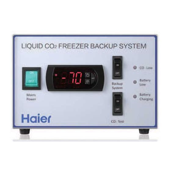
ULT Backup Refrigerator System
Operation Manual
HBX-IC
HBX-IIC
LIQUID CO
FREEZER BACKUP SYSTEM
2
Mains
Power
Read the Operation Manual carefully before using your appliance.
Keep the Operation Manual in a safe place.
Appearance, color and layout of the door may vary.
Translation of the original instruction
CO
Low
2
Battery
Backup
Low
System
Battery
Charging
CO
Test
2
Advertisement

Related Manuals for Haier HBX-IC


Summary of Contents for Haier HBX-IC
- Page 1 ULT Backup Refrigerator System Operation Manual HBX-IC HBX-IIC LIQUID CO FREEZER BACKUP SYSTEM Battery Backup System Mains Battery Power Charging Test Read the Operation Manual carefully before using your appliance. Keep the Operation Manual in a safe place. Appearance, color and layout of the door may vary.
- Page 2 ............. Product Introduction Description of Components ..........Precautions ................Transportation and Installation..........4 Installation ................Product Features ..............Unit Start-up and Tuning ............Maintenance ................ Technical Specification ............Package ................
- Page 3 System Switch Mains Power Test Switch Control Panel Door switch connector Power cable Output pipe Input pipe Door switch cable Sensor...
- Page 4 Haier 7.The plug on the power supply cord can be used as disconnect device which shall be easily accessible.
- Page 5 AC 220-240V, 50/60Hz.
-
Page 6: Installation
Installation 1.Install the liquid supply line onto the inlet port following the instruction label; Install the output capillary tube and the harness for the door switch switch on the backup control box. 2.Place the backup system control box on top of the freezer. Remove the cap for the port hole on the back of the freezer unit. - Page 7 3.Remove the two inner shelves inside the freezer. Run the capillary tube and temperature sensor across the port hole tunnel into the freezer. 4.Use aluminum clip provided to fasten the capillary tube roughly 150 mm from the tip of the injector. Use a self tapping screw 3.5 to fasten the clip to a prepunched hole locatde in the upper left of the unit.
- Page 8 5.Remove the fasteners for the sensor bracket. Use tie wraps to secure the backup control sensor and the freezer sensor together. Install the sensor bracket in place. 6.Use the insulation tube on the outlet line to seal both sides of the port holes to prevent leak of cold air. Install the shelves back in place.
- Page 9 7.Open the door switch terminal cover, which is located on the side of the compressor compartment cover. Connect both door switch terminals with each other. 8.Install the liquid supply line to the liquid feed line.
- Page 10 9.Plug in the power cord of the backup system to a power outlet. Turn on the main power switch and battery charge switch. The backup unit will keep the battery charged. Please note the backup system can operate independently for up to 12 hours.
- Page 11 Master power switch The main power switch must be turned on for the system to operate properly. Temperature display and indicator light The display screen shows the actual temperature in the storage cabinet; When the snow flake light is lit on the display, the feed solenoid valve is activated and the injection is in process.
-
Page 12: Temperature Adjustment
Temperature adjustment 1 Initial status of power on When installation of a backup system is completed, plug in the power cord to a power supply. Turn on the main power switch and the battery charge switch. The backup system is in the standby state. - Page 13 1.Power up the ULT freezer. Let it run to the set freezer temperature. 2.Turn on the main power switch and the battery charge switch on the backup system. 3.Start the test procedure. Set the backup system’s set point temperature 10 C colder than the actual freezer temperature. The backup system will start injecting coolant into the freezer.
- Page 14 Black Power board Battery switch CO2 test switch +12V PT100 CO2 test switch PT100 Electronic temperature controller HP pressure switch DC solenoid valve HBX-IC HBX-IIC 200 400 160 200 400 160 × × × × (mm) 0.25A 0.25A AC 220-240V, 50/60Hz...
- Page 15 Discharge Output pipe Input pipe Cableclip pipe Meaning of crossed out wheeled dustbin: Do not dispose of electrical appliances as unsorted municipal waste, use separate collection facilities. Contact your local government for information regarding the collection systems available. If electrical appliances are disposed of in landfills or dumps, hazardous substances can leak into the groundwater and get into the food chain, damaging your health and well-being.
- Page 16 Manufacturer: Qingdao Haier Biomedical Co.,Ltd. Address: Haier Industrial Park, Economic Technology Development Zone, Qingdao P.R. China Web:www.haiermedical.com Revision date:9/2018 Version:1st,2018 Dedicated code:0270501125 V13026...