ABB Relion 650 Series Product Manual
Breaker protection
Hide thumbs
Also See for Relion 650 Series:
- Technical manual (754 pages) ,
- Applications manual (382 pages) ,
- Commissioning manual (182 pages)
Table of Contents
Advertisement
Quick Links
Advertisement
Table of Contents

Related Manuals for ABB Relion 650 Series


Summary of Contents for ABB Relion 650 Series
- Page 1 ® Relion 650 SERIES Breaker protection REQ650 Version 1.1 IEC Product guide...
-
Page 2: Table Of Contents
Disclaimer The information in this document is subject to change without notice and should not be construed as a commitment by ABB Power Grids. ABB Power Grids assumes no responsibility for any errors that may appear in this document. Drawings and diagrams are not binding. -
Page 3: Series Overview
• Minimized parameter setting based on default values a single or double busbar section. and ABB's new global base value concept. You only • A breaker bay connecting a transmission line, with need to set those parameters specific to your own back-up protection functions enabling single phase application, such as the line data. - Page 4 IEC61850 TCS SCBR SPVN ZBAT DRP RDRE S SIMG IEC60870-5-103 IEC10000321-1-en.vsd IEC10000321 V1 EN-US Figure 1. A typical backup protection functions in a breaker bay giving three-phase trip ABB Power Grids © Copyright 2011 ABB Power Grids. All rights reserved...
- Page 5 A typical breaker bay connecting a transmission line, with back-up protection functions enabling single phase trip. The connection of the bay is only to a single busbar section ABB Power Grids © Copyright 2011 ABB Power Grids. All rights reserved...
- Page 6 A typical breaker bay connecting a transmission line, with back-up protection functions enabling single phase trip. The connection of the bay can be made to one of the double busbar sections ABB Power Grids © Copyright 2011 ABB Power Grids. All rights reserved...
-
Page 7: Available Functions
OV2PTOV Two step overvoltage protection ROV2PTOV Two step residual overvoltage protection LOVPTUV Loss of voltage check Frequency protection SAPTUF Underfrequency function SAPTOF Overfrequency function SAPFRC Rate-of-change frequency protection ABB Power Grids © Copyright 2011 ABB Power Grids. All rights reserved... - Page 8 Configurable logic blocks, Inverter gate PULSETIMER Configurable logic blocks, Pulse timer GATE Configurable logic blocks, Controllable gate Configurable logic blocks, exclusive OR gate LOOPDELAY Configurable logic blocks, loop delay ABB Power Grids © Copyright 2011 ABB Power Grids. All rights reserved...
- Page 9 Insulation gas monitoring function SSIML Insulation liquid monitoring function SSCBR Circuit breaker condition monitoring I103MEAS Measurands for IEC60870-5-103 I103MEASUSR Measurands user defined signals for IEC60870-5-103 I103AR Function status auto-recloser for IEC60870-5-103 ABB Power Grids © Copyright 2011 ABB Power Grids. All rights reserved...
- Page 10 GOOSEINTRCV GOOSE function block to receive an integer value GOOSEMVRCV GOOSE function block to receive a mesurand value GOOSESPRCV GOOSE function block to receive a single point value ABB Power Grids © Copyright 2011 ABB Power Grids. All rights reserved...
-
Page 11: Current Protection
Four step phase overcurrent protection OC4PTOC All IEC and ANSI time delayed characteristics are M12846-3 v8 The four step phase overcurrent protection function available. OC4PTOC has an inverse or definite time delay ABB Power Grids © Copyright 2011 ABB Power Grids. All rights reserved... - Page 12 ABB Power Grids © Copyright 2011 ABB Power Grids. All rights reserved...
-
Page 13: Voltage Protection
Two step residual overvoltage protection ROV2PTOV Reset times for both steps can be set as well. function calculates the residual voltage from the three- phase voltage input transformers or measures it from a ABB Power Grids © Copyright 2011 ABB Power Grids. All rights reserved... -
Page 14: Frequency Protection
Current circuit supervision CCSRDIF between the negative sequence and zero sequence M12444-3 v6 Open or short circuited current transformer cores can based algorithm. cause unwanted operation of many protection functions ABB Power Grids © Copyright 2011 ABB Power Grids. All rights reserved... -
Page 15: Control
It is especially used in the interlocking and reservation station-wide logics. Up to five reclosing attempts can be included by parameter setting. The first attempt can be single- ABB Power Grids © Copyright 2011 ABB Power Grids. All rights reserved... -
Page 16: Logic
SEMOD158421-5 v4 Integer to boolean conversion with logic node representation function (IB16FCVB) is used to transform • OR function block. an integer to 16 binary (logic) signals. ABB Power Grids © Copyright 2011 ABB Power Grids. All rights reserved... -
Page 17: Monitoring
Comtrade format. The same applies to all analog input signal. events, which are continuously saved in a ring-buffer. The local HMI is used to get information about the ABB Power Grids © Copyright 2011 ABB Power Grids. All rights reserved... -
Page 18: Metering
A time delay for the calculated by the function. overvoltage and undervoltage alarms can be set according to definite time characteristics. ABB Power Grids © Copyright 2011 ABB Power Grids. All rights reserved... -
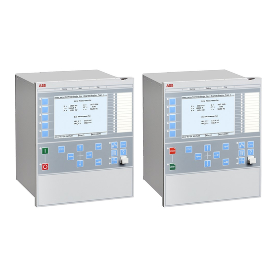
Page 19: Human Machine Interface
• By setting the IED in test mode in the local HMI PCM600 tool • Liquid crystal display (LCD) While the IED is in test mode, all functions are blocked. ABB Power Grids © Copyright 2011 ABB Power Grids. All rights reserved... -
Page 20: Station Communication
GOOSE performance requirements for information with a control system, and with a data tripping applications in substations, as defined by the ABB Power Grids © Copyright 2011 ABB Power Grids. All rights reserved... -
Page 21: Hardware Description
228.9 mm 300 mm 272 mm 254 mm 224 mm + 12 mm with ring-lug connector ∅6 mm 25.5 mm 482.6 mm (19") 265.9 mm (6U) 13 mm ABB Power Grids © Copyright 2011 ABB Power Grids. All rights reserved... -
Page 22: Connection Diagrams
296 mm Connection diagram, REQ650 1.1, (3Ph/1CB/1BB) A01 ∅6.8 mm 13 mm 1MRK006501-LB 268.9 mm Connection diagram, REQ650 1.1, (1Ph/1CB/1BB) A11 1MRK006501-RB Connection diagram, REQ650 1.1, (1Ph/1CB/2BB) B11 1MRK006501-SB ABB Power Grids © Copyright 2011 ABB Power Grids. All rights reserved... -
Page 23: Technical Data
100 V AC/ 110 V AC/ 115 V AC/ 120 V AC Voltage withstand: • Continuous 420 V rms • For 10 s 450 V rms Burden at rated voltage <0.05 VA Residual current Phase currents or residual current ABB Power Grids © Copyright 2011 ABB Power Grids. All rights reserved... - Page 24 15 A Make and carry for 0.5 s 30 A Breaking capacity when the control-circuit time constant L/R<40 ≤1 A/≤0.3 A/≤0.1 A ms, at U< 48/110/220 V DC ABB Power Grids © Copyright 2011 ABB Power Grids. All rights reserved...
- Page 25 Optical serial port, type ST for IEC 60870-5-103 Influencing factors GUID-59B01F47-1193-4243-B78C-EC6149CFA107 v12 IP15846-1 v1 Table 12. Degree of protection of flush-mounted IED Description Value Front side IP 40 Rear side, connection terminals IP 20 ABB Power Grids © Copyright 2011 ABB Power Grids. All rights reserved...
- Page 26 96 h at +85ºC Damp heat tests steady state 240 h at +40ºC IEC 60068-2-78 humidity 93% cyclic 6 cycles at +25 to +55ºC IEC 60068-2-30 humidity 93...95% ABB Power Grids © Copyright 2011 ABB Power Grids. All rights reserved...
- Page 27 IEC 60255-25 • Conducted, RF-emission (mains terminal) 0.15...0.50 MHz < 79 dB(µV) quasi peak < 66 dB(µV) average 0.5...30 MHz < 73 dB(µV) quasi peak < 60 dB(µV) average ABB Power Grids © Copyright 2011 ABB Power Grids. All rights reserved...
- Page 28 Bump test IEC 60255-21-2 Class 1 Seismic test IEC 60255-21-3 Class 2 Product safety GUID-2AA791D9-FA91-4F1F-A31D-64412575CE81 v8 Table 19. Product safety Description Reference LV directive 2006/95/EC Standard EN 60255-27 (2005) ABB Power Grids © Copyright 2011 ABB Power Grids. All rights reserved...
- Page 29 Breaker protection REQ650 1MRK 505 269-BEN B Version 1.1 IEC EMC compliance GUID-9B1F0C9F-664E-41C8-ADA3-4376E096A9C9 v4 Table 20. EMC compliance Description Reference EMC directive 2004/108/EC Standard EN 50263 (2000) EN 60255-26 (2007) ABB Power Grids © Copyright 2011 ABB Power Grids. All rights reserved...
- Page 30 45 ms typically at 10 to 0 x I Critical impulse time 2 ms typically at 0 to 10 x I Dynamic overreach < 5% at t = 100 ms ABB Power Grids © Copyright 2011 ABB Power Grids. All rights reserved...
- Page 31 25 ms typically at 2 to 0 x I funciton Critical impulse time 10 ms typically at 0 to 2 x I Impulse margin time 15 ms typically ABB Power Grids © Copyright 2011 ABB Power Grids. All rights reserved...
- Page 32 40 ms typically at 10 to 0 x I Critical impulse time 2 ms typically at 0 to 10 x I Dynamic overreach < 5% at t = 100 ms ABB Power Grids © Copyright 2011 ABB Power Grids. All rights reserved...
- Page 33 Operate time, directional start 30 ms typically at 0,5 to 2 x I function Reset time, directional start 30 ms typically at 2 to 0,5 x I function ABB Power Grids © Copyright 2011 ABB Power Grids. All rights reserved...
- Page 34 Reset time, non-directional 120 ms typically at 1.2 to 0.8 x U residual overvoltage Operate time, directional 260 ms typically at 0.5 to 2 x I residual over current ABB Power Grids © Copyright 2011 ABB Power Grids. All rights reserved...
- Page 35 ± 1.0% of I at I > I Reset ratio > 95% Timers (0.000-60.000) s ± 0.5% ±10 ms Operate time for current detection 35 ms typically Reset time for current detection 10 ms maximum ABB Power Grids © Copyright 2011 ABB Power Grids. All rights reserved...
- Page 36 Function Range or value Accuracy Operate value, current (0-100) % ± 1.0% of I asymmetry level Reset ratio >95% Time delay (0.000-60.000) s ± 0.5% ± 25 ms ABB Power Grids © Copyright 2011 ABB Power Grids. All rights reserved...
- Page 37 Accuracy valid for 50 Hz. At 60 Hz both accuracies are ±2.0% Accuracy valid for 50 Hz. At 60 Hz the accuracy is -50/+100% Accuracy valid for 50 Hz. At 60 Hz the accuracy is ±40% ABB Power Grids © Copyright 2011 ABB Power Grids. All rights reserved...
- Page 38 Reset time, start function 40 ms typically at 0.5 to 2 x U Critical impulse time 10 ms typically at 2 to 0 x U Impulse margin time 15 ms typically ABB Power Grids © Copyright 2011 ABB Power Grids. All rights reserved...
- Page 39 Operate voltage (0–100)% of UBase ± 0.5% of U Reset ratio <105% Pulse timer (0.050–60.000) s ± 0.5% ± 25 ms Timers (0.000–60.000) s ± 0.5% ± 25 ms ABB Power Grids © Copyright 2011 ABB Power Grids. All rights reserved...
- Page 40 (45.00 - 65.00) Hz ± 2.0 mHz Timers (0.000 - 60.000) s <130 ms Operate time, start function At 50 Hz: 100 ms typically At 60 Hz: 80 ms typically ABB Power Grids © Copyright 2011 ABB Power Grids. All rights reserved...
- Page 41 ± 0.5% ± 25 ms Time delay for energizing check (0.000-60.000) s ± 0.5% ± 25 ms Closing time for the circuit breaker (0.000-60.000) s ± 0.5% ± 25 ms ABB Power Grids © Copyright 2011 ABB Power Grids. All rights reserved...
- Page 42 CB check time before unsuccessful (0.00-6000.00) s Wait for master release (0.00-6000.00) s Wait time after close command before (0.000-60.000) s proceeding to next shot ABB Power Grids © Copyright 2011 ABB Power Grids. All rights reserved...
- Page 43 Accuracy 5 ms 20 ms 100 ms INVERTER SRMEMORY RSMEMORY GATE PULSETIMER (0.000–90000.000) s ± 0.5% ± 25 ms TIMERSET (0.000–90000.000) s ± 0.5% ± 25 ms LOOPDELAY ABB Power Grids © Copyright 2011 ABB Power Grids. All rights reserved...
- Page 44 Accuracy valid for 50 Hz. At 60 Hz the accuracy is <0.04. M13416-1 v4 Table 53. Event counter CNTGGIO Function Range or value Accuracy Counter value 0-10000 Max. count up speed 10 pulses/s ABB Power Grids © Copyright 2011 ABB Power Grids. All rights reserved...
- Page 45 Accuracy Depending on time synchronizing M13765-1 v3 Table 56. Indications DRPRDRE Function Value Buffer capacity Maximum number of indications presented for single disturbance Maximum number of recorded disturbances ABB Power Grids © Copyright 2011 ABB Power Grids. All rights reserved...
- Page 46 Table 61. Insulation gas monitoring function SSIMG Function Range or value Accuracy Pressure alarm 0.00-25.00 Pressure lockout 0.00-25.00 Temperature alarm -40.00-200.00 Temperature lockout -40.00-200.00 Timers (0.000-60.000) s ± 0.5% ± 110 ms ABB Power Grids © Copyright 2011 ABB Power Grids. All rights reserved...
- Page 47 Front side IP 40 Rear side, connection terminals IP 20 Table 67. Degree of protection of the LHMI Description Value Front and side IP 42 Dimensions GUID-33B28FB3-7FCF-4DEC-A194-C79D725805D6 v4 ABB Power Grids © Copyright 2011 ABB Power Grids. All rights reserved...
- Page 48 40 ms IEC Very inverse A=13.5, P=1.0 IEC Inverse A=0.14, P=0.02 IEC Extremely inverse A=80.0, P=2.0 IEC Short time inverse A=0.05, P=0.04 IEC Long time inverse A=120, P=1.0 ABB Power Grids © Copyright 2011 ABB Power Grids. All rights reserved...
- Page 49 EQUATION1437-SMALL V1 EN-US Type C curve: k = (0.05-1.10) in steps of 0.01 unless otherwise stated × æ ö > ç × ÷ 0.035 è ø > EQUATION1438-SMALL V1 EN-US ABB Power Grids © Copyright 2011 ABB Power Grids. All rights reserved...
- Page 50 > EQUATION1437-SMALL V1 EN-US Type C curve: k = (0.05-1.10) in steps of 0.01 × æ ö > ç × ÷ 0.035 è ø > EQUATION1438-SMALL V1 EN-US ABB Power Grids © Copyright 2011 ABB Power Grids. All rights reserved...
-
Page 51: Ordering
Selection for position #4. Additional HMI language No second HMI language Chinese Selection for position #4. Casing Notes and Rules Rack casing, 6 U 1/2 x 19" Selection for position #5. ABB Power Grids © Copyright 2011 ABB Power Grids. All rights reserved... - Page 52 Binary input/output module 9 BI, 3 NO Trip, 5 NO Signal, 1 CO p4, p5, p6 optional for A01 Signal p4=A, p5, p6 optional for A11/B11 Selection for position #10. ABB Power Grids © Copyright 2011 ABB Power Grids. All rights reserved...
- Page 53 Connectivity packages and LED label template is always included for each IED. Rule: Specify additional quantity of IED Connect CD requested User documentation 1MRK 003 500-AA Quantity : ABB Power Grids © Copyright 2011 ABB Power Grids. All rights reserved...
- Page 54 Reference information M2175-3 v4 For our reference and statistics we would be pleased to be provided with the following application data: Country: End user: Station name: Voltage level: ABB Power Grids © Copyright 2011 ABB Power Grids. All rights reserved...
- Page 55 Communication protocol manual, IEC 60870-5-103 1MRK 511 243-UEN Point list manual, DNP3 1MRK 511 244-UEN Engineering manual 1MRK 511 245-UEN Operation manual 1MRK 500 093-UEN Installation manual 1MRK 514 014-UEN ABB Power Grids © Copyright 2011 ABB Power Grids. All rights reserved...
- Page 57 ABB Power Grids Sweden AB Grid Automation Products SE-721 59 Västerås, Sweden Phone +46 (0) 10 738 00 00 Scan this QR code to visit our website https://www.abb.com/protection-control © Copyright 2011 ABB Power Grids. All rights reserved.