Table of Contents
Advertisement
Quick Links
SERVICE MANUAL
Ver. 1.1 2016.05
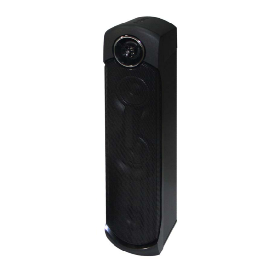
• SS-GT4DB is Speaker system in MHC-GT4D.
• All of the units included in the MHC-GT4D (SS-
GT4DB, SA-WGT4D, Remote control) are required
to confi rming operation of SS-GT4DB. Check in
advance that you have all of the units.
9-890-675-02
Sony Corporation
2016E80-1
©
2016.05
Published by Sony EMCS (Malaysia) PG Tec
T4D.
4D (SS-
required
Check in
SPECIFICATIONS
Speaker system
2-way, bass refl ex
Speaker unit (left/right)
Tweeters: 40 mm × 1, cone type
Midrange: 80 mm × 2, cone type
Rated impedance
5 ohms
Design and specifi cations are subject to
change without notice.
SS-GT4DB
Australian Model
SPEAKER SYSTEM
AEP Model
UK Model
E Model
Advertisement
Table of Contents

Related Manuals for Sony SS-GT4DB


Summary of Contents for Sony SS-GT4DB
- Page 1 • All of the units included in the MHC-GT4D (SS- 4D (SS- GT4DB, SA-WGT4D, Remote control) are required required to confi rming operation of SS-GT4DB. Check in Check in advance that you have all of the units. SPECIFICATIONS Speaker system 2-way, bass refl...
-
Page 2: Section 1 Disassembly
SS-GT4DB SECTION 1 DISASSEMBLY • This set can be disassembled in the order shown below. 1-1. DISASSEMBLY FLOW When disassembling the unit, use the following jig for speaker removal. Part No. Description 1-2. FRONT PANEL SECTION-1 J-2501-238-A JIG FOR SPEAKER REMOVAL (Page 2) 1-3. - Page 3 SS-GT4DB 1-3. FRONT PANEL SECTION-2 4 All bosses are removed while 2 Insert a flat-head screwdriver into moving jig in the direction of 3 Insert the jig into a space and raise the front panel section, and lift it a little.
- Page 4 SS-GT4DB 1-4. LOUDSPEAKER (4cm) (SP3) 1 two screws (+BVTP 3 2 loudspeaker (4cm) (SP3) 3 front panel section – Rear bottom view – 1-5. LOUDSPEAKER (8cm) (SP1, SP2) 4 four screws 8 loudspeaker (8cm) (SP1) (3.5 1 two screws (+BV TAPPING TYPE-1 3.5)
-
Page 5: Section 2 Diagrams
SS-GT4DB SECTION 2 DIAGRAMS THIS NOTE IS COMMON FOR PRINTED WIRING BOARDS AND SCHEMATIC DIAGRAMS. (In addition to this, the necessary note is printed in each block.) For Printed Wiring Boards. For Schematic Diagrams. Note: Note: • X : Parts extracted from the component side. - Page 6 SS-GT4DB 2-3. PRINTED WIRING BOARD – BAR_RGB_A, BAR_RGB_B Board (RIGHT) – • : Uses unleaded solder. BAR_RGB_A BOARD BAR_RGB_B BOARD (RIGHT) (RIGHT) RGB_SPLITTER BOARD CN1252 SA-WGT4D (Page 46) >011P CL1650 D1650 CL1653 CN1650 CL1600 CN1600 CL1651 CL1652 (11) D1600 1-980-567-...
-
Page 7: Section 3 Exploded View
SS-GT4DB Ver. 1.1 SECTION 3 EXPLODED VIEW Note: • -XX and -X mean standardized parts, so • Color Indication of Appearance Parts Ex- • Abbreviation they may have some difference from the ample: : Argentina model original one. KNOB, BALANCE (WHITE) . . . (RED) : Australian model •... -
Page 8: Section 4 Bar_Rgb_B Electrical Parts List
SS-GT4DB SECTION 4 Ver. 1.1 BAR_RGB_A BAR_RGB_B ELECTRICAL PARTS LIST Note: • Abbreviation • Due to standardization, replacements in • SEMICONDUCTORS : Argentina model the parts list may be different from the In each case, u: μ, for example: parts specified in the diagrams or the uA. - Page 9 SS-GT4DB MEMO...
-
Page 10: Revision History
SS-GT4DB REVISION HISTORY Ver. Date Description of Revision 2016.02 2016.05 Addition of African, Argentina, 220 240 V AC area in E model, Malaysia, Russian, Saudi Arabia and – Thai models. How to search for a contact point of signal lines or the like in DIAGRAMS SECTION If a contact point of a BLOCK DIAGRAM, PRINTED WIRING BOARD or SCHEMATIC DIAGRAM is shown in a different page, use the PDF fi...