Table of Contents
Advertisement
Quick Links
Advertisement
Table of Contents

Related Manuals for Samsung Ubigate iBG1003


Summary of Contents for Samsung Ubigate iBG1003
- Page 2 COPYRIGHT This manual is proprietary to SAMSUNG Electronics Co., Ltd. and is protected by copyright. No information contained herein may be copied, translated, transcribed or duplicated for any commercial purposes or disclosed to third parties in any form without the prior written consent of SAMSUNG Electronics Co., Ltd.
-
Page 3: General User Information
GENERAL USER INFORMATION Radio Frequency Interference The Ubigate iBG1003 equipment has been tested and found to comply with the limits for a Class A digital device, pursuant to FCC Part 15 Rules. These limits are designed to provide reasonable protection against harmful interference when the equipment is operated in a commercial environment. -
Page 4: Fcc Requirements
GENERAL USER INFORMATION FCC Requirements The Ubigate iBG1003 equipment complies with FCC Part 68 Rules and requirements adopted by Administrative Council for Terminal Attachment (ATCA). FCC Part 68 The FCC Part 68 label is located on the bottom of the chassis. -
Page 5: Telephone Connection Requirement
Ubigate iBG1003 Installation Manual/Ed.04 Telephone Connection Requirement A plug and jack is used to connect this equipment to the premises wiring and telephone network must comply with the FCC Part 68 rules and requirements adopted by the ACTA. A compliant telephone cord and modular plug is provided with this product which is designed to connect to a compatible Standard Modular jack. -
Page 6: Incidence Of Harm
Incidence of Harm The telephone company will notify you in advance about the temporary discontinuation of service, if the Ubigate iBG1003 equipment is causing harm to the telephone network. In case advance notification is not feasible, the telephone company will notify the customer as soon as possible and you will also be advised about your right to file a complaint with the FCC, if it is necessary. -
Page 7: General
Ubigate iBG1003 Installation Manual/Ed.04 General Connection to party line service is subject to state tariffs. Contact the State Public Utility Commission, Public Service Commission or Corporation Commission for information. Direct Inward Dialing (‘DID’) If the equipment is not operating as per the Proper Answer Supervision mentioned in FCC Part 68 rules, then it is a violation. -
Page 8: Electrical Safety Advisory
American Society of Composers, Authors and Publishers (ASCAP) or other similar organizations if copyright music is transmitted through the Music on Hold feature. SAMSUNG ELECTRONICS, CO., LTD. hereby disclaims any liability arising out of failure to obtain such a license. Direct Inward System Access (DISA) Warning The lines used for the DISA feature must have the disconnected Supervision option provided by the telephone company. -
Page 9: Safety Warnings
Every wire for communication should be larger than 26 AWG. Double pole/neutral fusing. Underwriters Laboratories The Ubigate iBG1003 system has been tested to comply with Safety Standards in the United States and Canada. This system is listed with Underwriters Laboratories. The cUL Mark is separately shown on the label. -
Page 10: Installation Safety Guidelines And Warnings
Cover Panels Do not operate the Ubigate iBG1003 with missing blank faceplates and cover panels. These covers prevent exposure to hazardous voltages and currents inside the chassis. They are important to maintaining proper air flow through the chassis. - Page 11 Discharge (ESD) damage, which can cause intermittent or complete component failures. When handling Ubigate iBG1003 or its components, wear grounding wrist straps to avoid ESD damage to the equipment. Do not directly touch the backplane with your hand or any metal tool, or you could shock yourself.
- Page 12 GENERAL USER INFORMATION This page is intentionally left blank. © SAMSUNG Electronics Co., Ltd.
-
Page 13: Introduction
Ubigate iBG1003 Installation Manual INTRODUCTION Purpose This document provides instructions on installing the Ubigate iBG1003™, along with hardware descriptions, safety information, and pre-installation requirements. Document Content and Organization This manual is composed of five Chapters and two Annexes. CHAPTER 1. Ubigate iBG1003 Overview Describes Ubigate iBG1003 characteristics. -
Page 14: Conventions
CAUTION Provides information or instructions that the reader should follow in order to avoid a service failure or damage to the system. NOTE Indicates additional information as a reference. © SAMSUNG Electronics Co., Ltd. -
Page 15: Information For Product And Technical Support
Ubigate iBG1003 Installation Manual/Ed.04 Information for Product and Technical Support For questions regarding the product and technical supports: http://www.samsungnetwork.com Revision History EDITION DATE OF ISSUE REMARKS 04. 2009. First Edition 06. 2009. Modified voice connector description 09. 2009. Added VOM-4P 12. - Page 16 INTRODUCTION This page is intentionally left blank. © SAMSUNG Electronics Co., Ltd.
-
Page 17: Safety Concerns
Ubigate iBG1003 Installation Manual SAFETY CONCERNS The purpose of the Safety Concerns section is to ensure the safety of users and prevent property damage. Please read this document carefully for proper use. Symbols Caution Indication of a general caution. Restriction Indication for prohibiting an action for a product. -
Page 18: Warning
(SELV) circuits (as found in LAN ports) to Telephone-Network Voltage (TNV) circuits (as found in WAN ports). AC power to the Ubigate iBG1003 is double fused. Fuses are installed on both line and neutral conductors. A neutral fuse failure may present a hazard to service personnel. - Page 19 Ubigate iBG1003 Installation Manual/Ed.04 Caution CAUTION Do not place any items that weigh more than 4.5 kg on top of the chassis, and do not stack routers on a desktop. Practice good safety habits. Use two people to mount the Ubigate iBG1003 into a rack.
- Page 20 SAFETY CONCERNS This page is intentionally left blank. XVIII © SAMSUNG Electronics Co., Ltd.
-
Page 21: Table Of Contents
Ubigate iBG1003 Installation Manual TABLE OF CONTENTS GENERAL USER INFORMATION Radio Frequency Interference ..................I FCC Requirements ......................II Unauthorized Modifications ................... II Telephone Connection Requirement ................III Ringer Equivalence Number ..................III Incidence of Harm ......................IV Changes to Telephone Company Equipment or Facilities ..........IV Service Center ...................... - Page 22 TABLE OF CONTENTS Caution ........................XVII CHAPTER 1. Ubigate iBG1003 Overview Overview of Ubigate iBG1003 Router ................1-2 Ubigate iBG1003 Front Side ..................1-2 Ubigate iBG1003 Rear Side ..................1-4 Ubigate iBG1003 Hardware ....................1-5 Modules and Internal Option Modules ................ 1-5 Power Supply ......................
- Page 23 Ubigate iBG1003 Installation Manual/Ed.04 50-Pin Champ Connector Port ..................4-7 PRI Port ........................4-8 Powering Up the Ubigate iBG1003 ................. 4-9 Connecting AC Power ....................4-9 Applying Power ......................4-10 CHAPTER 5. Option Module Installation General Maintenance Guidelines ..................5-1 Mini-Module Overview .....................
- Page 24 Figure 3.1 Bracket installation for front mounting ............. 3-2 Figure 3.2 Rack Mounting the Router ............... 3-3 Figure 3.3 Ground Connection on Ubigate iBG1003 ..........3-3 Figure 4.1 Connecting Console Cable ..............4-2 Figure 4.2 Connecting LAN Cable ................4-3 Figure 4.3 Connecting T1/E1 Cable .................
-
Page 25: Chapter 1. Ubigate Ibg1003 Overview
This chapter provides an overview of the Ubigate iBG1003. It provides information about front and rear panels, and cable connection ports. The Ubigate iBG1003 is a voice-centric WAN router. It is a desktop unit and has four T1/E1 ports and two Ethernet ports by default. Depending on the sub models, it has two sets of voice ports consisting of FXO, FXS, and T1/E1 PRI ports to provide voice services. -
Page 26: Overview Of Ubigate Ibg1003 Router
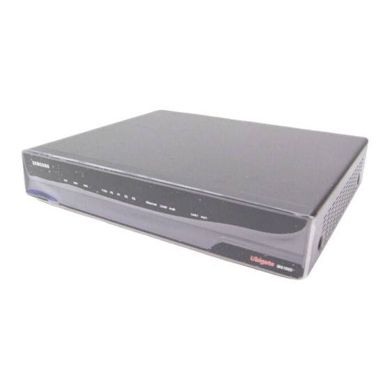
Additional information is also provided about external cables, wiring, and connection points. Ubigate iBG1003 Front Side The front side of the Ubigate iBG1003 has LEDs to indicate the iBG1003 router’s performance and operation status, as shown in figure below. Figure 1.1 Ubigate iBG1003 Front View Proper LED status is shown in the following table. - Page 27 Ubigate iBG1003 Installation Manual/Ed.04 (Continued) Indication & Color Description Solid green Fan is operating properly. Solid red Fan present but malfunctioning. Fan has been stopped by user configuration. P0~P3 Solid green T1/E1 port is operating normally. (T1/E1) Solid red T1/E1 port cable is not connected properly or critical alarm detected.
-
Page 28: Ubigate Ibg1003 Rear Side
CHAPTER 1. Ubigate iBG1003 Overview Ubigate iBG1003 Rear Side Ubigate iBG1003 rear side has several interface ports and slots as shown in figure below. Power connector, power switch, and ground stud are also located in the rear side. Ground Power Switch... -
Page 29: Ubigate Ibg1003 Hardware
IOMs will be released in the future. Voice Option Modules Ubigate iBG1003 can accommodate a voice option module using a voice option module slot. One is pre-assembled and shipped from the factory in order to meet different deployment needs. The following voice option modules are present: ... -
Page 30: Ventilation
On both sides, there are grids of holes where air comes in and goes out. When installing Ubigate iBG1003, ensure to make room around the system in order not to block air flow. -
Page 31: Chapter 2. Pre-Installation Requirements
Ubigate iBG1003 Installation Manual CHAPTER 2. Pre-Installation Requirements This chapter describes site requirements and equipment needed to install your Ubigate iBG1003 router Before you install Ubigate iBG1003, familiarize yourself with the network interface, power, and ground connections as described in the next sections. -
Page 32: Environment
Allow at least 30-inch (76.2 cm) both in front of and behind the router. Figure 2.1 Top view of the cooling air path through the chassis © SAMSUNG Electronics Co., Ltd. -
Page 33: Inspecting The Ubigate Ibg1003
Ubigate iBG1003 Quick Start Guide Ubigate iBG1003 Manual CD If any part is missing or damaged, contact Samsung Technical Support: http://www.samsung.com/global/business/telecomm/footer/Footer_ContactUs. html Save the shipping crate cover, pallet, and packing materials in case you need to move or ship the router at a later time. -
Page 34: Required Tools And Materials
To unpack the router and prepare for installation, you need the following tools: Number 2 Phillips screwdriver-to attach the rack-mounting brackets to Ubigate iBG1003. Number 3 Phillips screwdriver-to attach the Ubigate iBG1003 to the equipment rack. Small flat-blade screwdrivers-to install ground and an external alarm. Materials... -
Page 35: Chapter 3. Ubigate Ibg1003 Installation
Desktop Installation For installing chassis, you must secure unrestricted airflow for chassis cooling. Place the Ubigate iBG1003 router on a clean flat stable surface with at least 18 by 19 inch of clear space to allow sufficient room for interface cabling, power cord clearance, and adequate ventilation. -
Page 36: Rack Mount Installation
CHAPTER 3. Ubigate iBG1003 Installation Rack Mount Installation Attaching Rack-Mount Brackets Before installing the router on a rack, you need to attach brackets to the router. The brackets can be ordered separately. Attach the mounting brackets to the router as shown in figure below, using the 4 of M4xL8 screws included. -
Page 37: Figure 3.2 Rack Mounting The Router
Ubigate iBG1003 Installation Manual/Ed.04 Installing in a Rack Attach the Ubigate iBG1003 to the rack as shown in figure below, using 4 screws provided with the rack. Figure 3.2 Rack Mounting the Router Grounding the Ubigate iBG1003 You must connect the chassis to a reliable earth ground as shown in below figure. - Page 38 CHAPTER 3. Ubigate iBG1003 Installation This page is intentionally left blank. © SAMSUNG Electronics Co., Ltd.
-
Page 39: Chapter 4. Connecting The Ubigate Ibg1003
Connecting the Ubigate iBG1003 This section describes procedures to connect various interfaces and console port of the Ubigate iBG1003. Follow the procedures for interfaces appropriate for your network facility environment. © SAMSUNG Electronics Co., Ltd. -
Page 40: Console Port
CHAPTER 4. Connecting the Ubigate iBG1003 Console Port A terminal (VT-100 or equivalent) or workstation with terminal emulation software can be used for the operator console. To use a system console to configure and manage the router, connect it to the console port of the Ubigate iBG1003. -
Page 41: Ethernet Port
Ubigate iBG1003 Installation Manual/Ed.04 Ethernet Port The Ubigate iBG1003 has two 10/100 Mbps Ethernet ports. Use a Category 5 (minimum) Ethernet cable with RJ-45 connectors to connect to the network via an Ethernet port. Plug one end of the Ethernet cable into the appropriate Ethernet port on the target router. -
Page 42: T1/E1 Port
CHAPTER 4. Connecting the Ubigate iBG1003 T1/E1 Port The Ubigate iBG1003 has four built-in T1/E1 ports for data and two optional T1/E1 ports for voice. To connect a T/1E1 cable: Plug one end of the T1/E1 cable into an appropriate T1/E1 port on the target router. -
Page 43: Fxo Port
Ubigate iBG1003 Installation Manual/Ed.04 FXO Port The Ubigate iBG1003 has built-in two FXO ports, depending on sub-models. These ports provide two analog voice channel ports for connections to PBX station lines or FXS/DID lines from a Central Office of the Public Switched Telephone Network (PSTN). -
Page 44: Fxs Port
CHAPTER 4. Connecting the Ubigate iBG1003 FXS Port The Ubigate iBG1003 has four FXS ports, depending on sub-models. These ports provide 4 analog voice channel ports which connect with Plain Old Telephone Services (POTS) telephones. To connect an FXS cable: Figure 4.5 Connecting an FXS Cable... -
Page 45: 50-Pin Champ Connector Port
Ubigate iBG1003 Installation Manual/Ed.04 50-Pin Champ Connector Port The Ubigate iBG1003 has a 50-pin Champ connector port to support eight or sixteen FXS ports, depending on sub-modles. The port is connected as shown below: Figure 4.6 Connecting 50-pin Champ Connector Port For more information on cable specification, see 50-pin Champ Connector Cable in Annex B. -
Page 46: Pri Port
CHAPTER 4. Connecting the Ubigate iBG1003 PRI Port The Ubigate iBG1003 has two PRI ports, depending on sub-models. These ports provide two generic T1 or E1 trunk interfaces for voice. These module provide 2 T1 ports, running at 1.544 Mbps and supporting 24 voice timeslots. -
Page 47: Powering Up The Ubigate Ibg1003
Ubigate iBG1003 Installation Manual/Ed.04 Powering Up the Ubigate iBG1003 The Ubigate iBG1003 has a 72 Watts AC power supply module. Connecting AC Power To connect the AC power cord to the router: Connect the AC power connector to the power supply. -
Page 48: Applying Power
To apply power to the Ubigate iBG1003: Ensure that the Ubigate iBG1003 is connected to a power source. Switch the rocker switch on the Ubigate iBG1003 back panel to the on position (I). Then, the fan starts, the LEDs start to blink in different colors, and the Ubigate iBG1003 performs a self test. -
Page 49: Chapter 5. Option Module Installation
Read ‘Installation Safety Guidelines and Warnings’ before you start installing the option modules. General Maintenance Guidelines Keep all Ubigate iBG1003 option modules dry and dust-free, and store them in electrical-equipment-friendly environments. Mini-Module Overview Ubigate iBG1003 has one mini-module slot to accommodate optional WAN or LAN interface module. -
Page 50: Atop-1 (1-Port Adsl Over Pots Mini-Module)
The module has one ADSL port and one Ethernet port. The ADSL port should be connected with POTS network. However, the Ethernet port is for use in other iBG models. Therefore, the Ethernet port should not be connected to any other device or port. © SAMSUNG Electronics Co., Ltd. -
Page 51: Atoi-1 (1-Port Adsl Over Isdn Mini-Module)
Ubigate iBG1003 Installation Manual/Ed.04 Figure 5.2 Connecting the ATOP-1 Mini-Module ATOI-1 (1-Port ADSL over ISDN Mini-Module) This module provides an ADSL interface connecting to the Central Office through an ISDN line. LINK ADSL ATOI-1 Figure 5.3 ATOI-1 Mini-Module ADSL Port LEDs Indication &... -
Page 52: Figure 5.4 Connecting The Atoi-1 Mini-Module
Therefore, the Ethernet port should not be connected to any other device or port. Figure 5.4 Connecting the ATOI-1 Mini-Module For more information on cable specification, see ATOP-1, ATOI-1 Port Cable in Annex B. © SAMSUNG Electronics Co., Ltd. -
Page 53: Lmf-4M (4-Port Fast Ethernet Mini-Module)
Ubigate iBG1003 Installation Manual/Ed.04 LMF-4M (4-Port Fast Ethernet Mini-Module) This module provides four 10/100 Base-T Ethernet ports. FE 3 FE 2 FE 1 Figure 5.5 LMF-4M Mini-Module The following table explains the LEDs states in detail. Indication & Color Description... -
Page 54: Installing Mini-Modules
ESD (Electrostatic Discharge) handling practices to avoid damage to module components. When handling Ubigate iBG1003 or its components, wear grounding wrist straps to avoid ESD damage to the equipment. Do not directly touch the backplane with your hand or any metal tool, or you could shock yourself. - Page 55 Ubigate iBG1003 Installation Manual/Ed.04 Tighten all the screws completely. To remove an existing mini-module: Loosen the 2 retention screws on the back module panel. Pull the module out of the slot. In case, if the slot has to remain empty, cover the hole with a slot cover by aligning the slot cover’s screws with the screw holes on the...
-
Page 56: Port Numbering
(left most) numbered port. © SAMSUNG Electronics Co., Ltd. -
Page 57: Ibg1003 Port Numbering
Ubigate iBG1003 Installation Manual/Ed.04 iBG1003 Port Numbering The main system of an iBG1003 is considered as network module slot 0. Thus, built-in ports on the system such as 4 T1/E1 ports and Ethernet ports are numbered in 0/x format. Specifically, the Fast Ethernet ports are numbered 0/0 and 0/1, starting from right to left. - Page 58 CHAPTER 5. Option Module Installation This page is intentionally left blank. 5-10 © SAMSUNG Electronics Co., Ltd.
-
Page 59: Annex A. System Specifications
- Typical: 512 MB - Maximum: 1 GB u-SD Flash Memory - Typical: 1 GB - Maximum: 2 GB * For normal operation, only Samsung certified u-SD should be used. Boot Flash Memory 2 MB AC Power Supply - Input Voltage: 100~240 V... - Page 60 ANNEX A. System Specifications (Continued) Item Specification Regulatory & Safety Compliance - KCC Type Approval/EMC Registration - IEC 60950-1/EN 60950-1/UL 60950-1 - EN 55022/EN 55024/EN 61003-3-2/ EN 61003-3-3 - FCC Part 15 Class A - FCC Part 68 © SAMSUNG Electronics Co., Ltd.
-
Page 61: Interface Specifications
Ubigate iBG1003 Installation Manual/Ed.04 Interface Specifications The below section provides specifications for T1/E1 WAN interface and Ethernet interface. T1 WAN Interface Item Specification Receive line rate 1.544 Mbps ± 32 ppm Line code B8ZS or AMI Framing D4 or ESF Interface ESF FDL - AT &... -
Page 62: Ethernet Interface
ANNEX A. System Specifications Ethernet Interface Item Specification Data flow Full-duplex or half-duplex Connectors RJ-45 Data speed 10/100 Mbps, auto negotiating © SAMSUNG Electronics Co., Ltd. -
Page 63: Annex B. Cable Specifications
Ubigate iBG1003 Installation Manual ANNEX B. Cable Specifications Console Port Cable Cable Shape Figure B.1 Console Port Cable Cable Signaling and Pinout Console Port RJ-45 to RJ-45 RJ-45 to DB-9 Terminal Adapter Console (DTE) Rollover Cable (connected to Rollover Cable) -
Page 64: Ethernet Cable
Figure B.2 Ethernet LAN Interface Cable Cable Signaling and Pinout RJ45 Pin # Wire Color (T568A) 1000Base-T Signal White/Green BI_DA+ Green BI_DA- White/Orange BI_DB+ Blue BI_DC+ White/Blue BI_DC- Orange BI_DB- White/Brown BI_DD+ Brown BI_DD- © SAMSUNG Electronics Co., Ltd. -
Page 65: T1/E1 Cable
Ubigate iBG1003 Installation Manual/Ed.04 T1/E1 Cable Cable Shape RJ-48C to RJ-48C Cable Figure B.3 T1/E1 WAN Interface Cable Cable Signaling and Pinout Signal Signal RXRING TXRING RXTIP TXTIP TXRING RXRING TXTIP RXTIP © SAMSUNG Electronics Co., Ltd. -
Page 66: Lmf-4M Port Cable
10/100Base-T interfaces Figure B.4 LMF-4M Port Cable Cable Signaling and Pinout RJ45 Pin # Wire Color (T568A) 1000Base-T Signal White/Green BI_DA+ Green BI_DA- White/Orange BI_DB+ Blue BI_DC+ White/Blue BI_DC- Orange BI_DB- White/Brown BI_DD+ Brown BI_DD- © SAMSUNG Electronics Co., Ltd. -
Page 67: Atop-1, Atoi-1 Port Cable
Ubigate iBG1003 Installation Manual/Ed.04 ATOP-1, ATOI-1 Port Cable Cable Shape Figure B.5 ATOP-1, ATOI-1 Port Cable Cable Signaling and Pinout RJ-11 connector RJ-11 connector Signal Signal Ring Ring © SAMSUNG Electronics Co., Ltd. -
Page 68: Rj-21 Champ Connector Cable
TIP 3 TIP 16 RING 3 RING 16 TIP 4 RING 4 TIP 5 RING 5 TIP 6 RING 6 TIP 7 RING 7 TIP 8 RING 8 TIP 9 RING 9 TIP 10 RING 10 © SAMSUNG Electronics Co., Ltd. - Page 69 Ubigate iBG1003 Installation Manual/Ed.04 (Continued) RJ-21 RJ-21 Signal RJ-21 RJ-21 Signal (Left) (Right) name (Left) (Right) name TIP 11 RING 11 TIP 12 RING 12 TIP 13 RING 13 © SAMSUNG Electronics Co., Ltd.
-
Page 70: Fxo, Fxs Port Cable
ANNEX B. Cable Specifications FXO, FXS Port Cable Cable Shape Figure B.7 FXO, FXS Port Cable Cable Signaling and Pinout RJ-11 connector RJ-11 connector Signal Signal Ring Ring © SAMSUNG Electronics Co., Ltd. - Page 71 Installation Manual © 2009~2010 Samsung Electronics Co., Ltd. All rights reserved. Information in this manual is proprietary to SAMSUNG Electronics Co., Ltd. No information contained here may be copied, translated, transcribed or duplicated by any form without the prior written consent of SAMSUNG.