Advertisement
Quick Links
MANUFACTURED FOR:
MITSUBISHI ELECTRIC US, INC.
TECHNICAL & SERVICE MANUAL
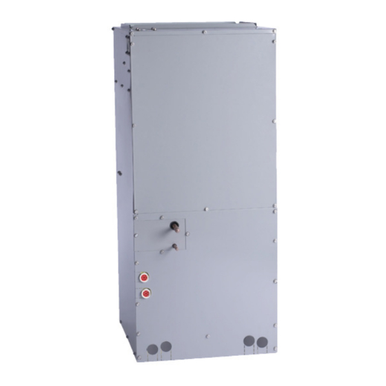
Series PVFY
<Indoor unit>
PVFY-P12E00B, PVFY-P18E00B
Models
PVFY-P24E00B, PVFY-P30E00B
PVFY-P36E00B, PVFY-P48E00B
PVFY-P54E00B
Specifications are subject to change without notice.
© 2013 Mitsubishi Electric US, Inc.
Vertical Concealed Indoor Unit "B"
2013
CONTENTS
SAFETY PRECAUTIONS ·························
1. FEATURES············································
2. PART NAMES AND FUNCTIONS ········
3. SPECIFICATION ···································
4. OUTLINES AND DIMENSIONS············
5. WIRING DIAGRAM ·····························
7. TROUBLESHOOTING ························
For use with R410A only
1
3
4
7
9
12
13
14
Advertisement

Related Manuals for Mitsubishi Electric PVFY Series


Summary of Contents for Mitsubishi Electric PVFY Series
-
Page 1: Table Of Contents
2. PART NAMES AND FUNCTIONS ········ 3. SPECIFICATION ··································· 4. OUTLINES AND DIMENSIONS············ 5. WIRING DIAGRAM ····························· 6. REFRIGERANT SYSTEM DIAGRAM···· 7. TROUBLESHOOTING ························ For use with R410A only Specifications are subject to change without notice. © 2013 Mitsubishi Electric US, Inc. -
Page 2: Safety Precautions
Install the air unit at a place that can withstand its weight. is shorted and operated forcibly, or parts other than those specified - Inadequate strength may cause the unit to fall down, resulting in by Mitsubishi Electric are used, fire or explosion may result. injuries. •... - Page 3 - Using a charging cylinder may cause the refrigerant to deteriorate. • Be especially careful when managing the tools. - If dust, dirt, or water gets in the refrigerant cycle, the refrigerant may deteriorate. Specifications are subject to change without notice. © 2013 Mitsubishi Electric US, Inc.
-
Page 4: Features
8.8 / 10.0 30,000 / 34,000 PVFY-P36E00B 10.6 / 11.7 36,000 / 40,000 PVFY-P48E00B 14.1 / 15.8 48,000 / 54,000 PVFY-P54E00B 15.8 / 17.6 54,000 / 60,000 Specifications are subject to change without notice. © 2013 Mitsubishi Electric US, Inc. -
Page 5: Part Names And Functions
• Never place any obstacle around the lower right-hand section of the remote controller. Doing so can result in the erroneous measurement of room temperature. Specifications are subject to change without notice. © 2013 Mitsubishi Electric US, Inc. - Page 6 COOL, DRY, AUTO, FAN, HEAT “Locked” indicator Set temperature Power ON Louver Ventilation Filter sign Set effective for 1 hr. Sensor position Room temperature Airflow Fan speed Specifications are subject to change without notice. © 2013 Mitsubishi Electric US, Inc.
-
Page 7: Specification
Heating | Indoor: 70˚ F (21˚ C) DB; Outdoor: 47˚F (8˚ C) DB/43˚F (6˚ C) WB. *2 Airflow rate / sound pressure levels are at low-mid-high fan speed. *3 Measured at medium static setting. Specifications are subject to change without notice. © 2013 Mitsubishi Electric US, Inc. - Page 8 6.4 (0~2000 5.2 (0~2000pulse) EDM-804MD 3.2 (0~2000pulse) EDM-402MD pulse) EDM-A0Y Power supply (L1,L2,G) 330V 30A terminal Trans- mission (1,2),(M1,M2,S) 330V 30A terminal TB15 Specifications are subject to change without notice. © 2013 Mitsubishi Electric US, Inc.
-
Page 9: Outlines And Dimensions
OUTLINES AND DIMENSIONS PVFY-P12,18,24E00B Units: Inches Specifications are subject to change without notice. © 2013 Mitsubishi Electric US, Inc. - Page 10 PVFY-P30,36E00B Units: Inches Specifications are subject to change without notice. © 2013 Mitsubishi Electric US, Inc.
- Page 11 PVFY-P48,54E00A Units: Inches Specifications are subject to change without notice. © 2013 Mitsubishi Electric US, Inc.
-
Page 12: Wiring Diagram
WIRING DIAGRAM PVFY-P12, P18, P24, P30, P36, P48, P54E00B · PVFY-P12,18,24,30,36,48,54E00B Specifications are subject to change without notice. © 2013 Mitsubishi Electric US, Inc. -
Page 13: Refrigerant System Diagram
9.52 (3/8) Electrical Component Location Circuit Board Speed Relays High M1 M2 S 24 VAC 27 VAC Line Voltage TB15 Terminal Strip Terminal Terminal Transformers 208/230V 1ph. Specifications are subject to change without notice. © 2013 Mitsubishi Electric US, Inc. -
Page 14: Troubleshooting
Refer to the next page for a detail. CN60 White Normal Abnormal Yellow (1)-(5) (2)-(6) (3)-(5) (4)-(6) Orange White-Red Yellow-Brown Orange-Red Blue-Brown Open or short Blue Brown Specifications are subject to change without notice. © 2013 Mitsubishi Electric US, Inc. - Page 15 Controller board DC12V Linear expansion valve Brown Blue Drive circuit ø4 ø4 Blue Brown ø3 ø3 Orange Yellow ø2 ø2 Yellow White Orange ø1 ø1 White Connector(CN60) Specifications are subject to change without notice. © 2013 Mitsubishi Electric US, Inc.
- Page 16 Check the color of lead wire and missing terminal of the con- Disconnect the connector the connector or nector. at the controller board, contact failure. then check the continuity. Specifications are subject to change without notice. © 2013 Mitsubishi Electric US, Inc.
- Page 17 If the line voltage supply is within range and 24 volts is supplied to any of the connector combinations shown in the chart above and the motor does not operate, replace the motor. Specifications are subject to change without notice. © 2013 Mitsubishi Electric US, Inc.
- Page 18 :The DipSW setting is effective during unit stopping ( remote controller OFF ) for SW1,2,3 and 4 commonly and the power source is not required to reset. Specifications are subject to change without notice. © 2013 Mitsubishi Electric US, Inc.
- Page 19 <At delivery> SW14 Note: 1 Note 1: The DipSW setting is effective while the unit is not operating (remote controller OFF) for SW 11, 12, 14, and 5. Specifications are subject to change without notice. © 2013 Mitsubishi Electric US, Inc.
- Page 20 MANUFACTURED FOR: MITSUBISHI ELECTRIC US, INC. Specifications are subject to change without notice. © 2013 Mitsubishi Electric US, Inc.