Table of Contents
Advertisement
Installation and Operating Instructions
READ AND SAVE THESE INSTRUCTIONS
Thank you for purchasing this Panasonic product.
Please read these instructions carefully before attempting to install, operate or service the
Panasonic product. Please carefully read the "GENERAL SAFETY INFORMATION" (P.2 ~ 3) of
this manual before use. Failure to comply with instructions could result in personal injury or
property damage. Please explain to users how to operate and maintain the product after
installation, and this booklet should be presented to users.
Please retain this booklet for future reference.
Energy Recovery Ventilator
CONTENTS
Model No.
BACK COVER
BACK COVER
2 ~ 3
4
4
4
5
6
6 ~ 7
8 ~ 9
9 ~ 12
13
14
14 ~ 16
17 ~ 18
19
Advertisement
Table of Contents

Related Manuals for Panasonic FV-10VEC2R


Summary of Contents for Panasonic FV-10VEC2R
-
Page 1: Table Of Contents
Please read these instructions carefully before attempting to install, operate or service the Panasonic product. Please carefully read the “GENERAL SAFETY INFORMATION” (P.2 ~ 3) of this manual before use. Failure to comply with instructions could result in personal injury or property damage. -
Page 2: General Safety Information
GENERAL SAFETY INFORMATION For Your Safety To reduce the risk of injury, loss of life, electric shock, fire, malfunction, and damage to equipment or property, always observe the following safety precautions. Explanation of symbol word panels The following symbol word panels are used to classify and describe the level of hazard, injury, and property damage caused when the denotation is disregarded and improper use is performed. - Page 3 GENERAL SAFETY INFORMATION Ceiling joist and wall stud must be subjected to static load more than five times the weight of the product. The special-purpose or dedicated parts, such as mounting fixtures, must be used if such parts are provided. Sufficient air is needed for proper combustion and exhausting of gases through the flue (chimney) of fuel burning equipment to prevent backdrafting.
-
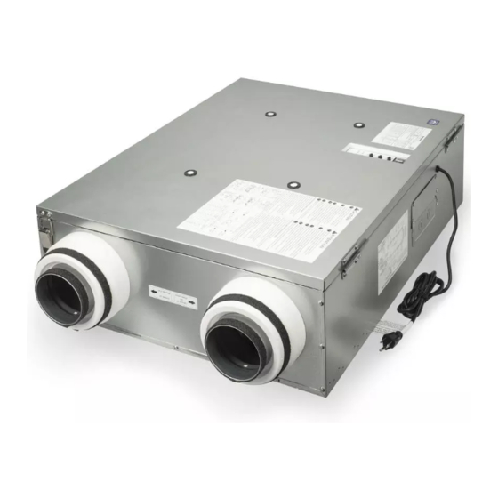
Page 4: Description
DESCRIPTION The Panasonic Energy Recovery Ventilator (ERV) uses 2 blower fans driven by 2 DC motors. The motor is designed to have an extended service life with reduced energy consumption. It also incorporates a thermal-cutoff for safety. The exhaust air (EA) duct includes an electric damper to prevent backdrafting. The outside air (OA) duct includes an electric damper to prevent backdrafting. -
Page 5: Dimensions
DIMENSIONS Unit: inches (mm) 35 13/16 (909.6) EA: Exhaust air 28 1/2 (723.6) 3 15/16 OA: Outside air (99.2) SA: Supply air RA: Return air 8 7/8 (225.6) Part name Part name Frame cover SA fan assy. Frame body SA adapter Maintenance plate RA filter Wiring cover RA adapter... -
Page 6: Wiring Diagram
WIRING DIAGRAM WIRING METHOD Note (1)The HVAC/AHU signal cord, wall switch cord, boost switch cord, wall switch and boost switch are not supplied. (2)The terminal of wall switch has been connected by jumper cable for factory default. Jumper cable (3) If a wall switch is not used to power down the ERV note that cutting power by unplugging the unit, and/or opening the frame cover to maintenance, will disallow the unit to run a power down process;... - Page 7 WIRING METHOD CAUTION Knock-out hole for Knock-out hole HVAC/AHU signal for wall switch cord connection The capacity of wall switch, boost switch cord and boost should be more than 120 V ~ 3 A to control switch cord Wiring cover the power of the product.
-
Page 8: Installation (Wall Mount)
INSTALLATION (WALL MOUNT) This method can be used in stud as below. Unit: inches (mm) Edge without Wall Unit: inches (mm) flange bracket 16 (406.4) 14 1/2 (368.3) 19 (482.6) 17 1/2 (444.5) Flange Stud 24 (609.6) 22 1/2 (571.5) 4-long screws (ST4.2x20) 1.Mount wall bracket on stud with long screws... -
Page 9: Ductwork
INSTALLATION (WALL MOUNT) Unit: inches (mm) Power cord 24 (609.6) 19 (482.6) 16 (406.4) Wall bracket Fig.4 3.Hang ERV on to wall bracket. CAUTION 2-long screws (ST4.2x20) Make sure the power cord is upward. (Fig.4) 4.Mount L plate on to stud with long screws (ST4.2X20). - Page 10 DUCTWORK Return Return air 40" (1 m) Min. 36” Dampers for (914 mm) balancing Min. Outdoors airflows furnace Note (1)Must have 2-3 feet of straight duct run from all duct attachment points on the ERV. Do not use any elbows or other peripheral pieces inside of 2-3 feet when attaching duct runs to the ERV.
- Page 11 DUCTWORK Return air from various parts of home. Return air (i.e. bathrooms, kitchens, utility areas) Return air Dampers for 36” Outdoors balancing airflows (914 mm) Min. Note furnace (1)Must have 2-3 feet of straight duct run from all duct attachment points on the ERV.
- Page 12 DUCTWORK 2.Install insulated ducts to OA and EA adapter. OA and EA adapter (Fig.13-1) (1)Pull back the insulation to expose the flexible Attach to 4” Attach to 6” duct. adapter adapter (2)Attach the flexible duct to the adapter using tie wrap. You can attach to the 4 inch or 6 inch according to size of flexible duct.
-
Page 13: Installation (Chain Mount)
INSTALLATION (CHAIN MOUNT) This method should be used in 24” joist as 5-long Unit: inches (mm) below. screws 24 (609.6) Unit: inches (mm) (ST4.2X20) 22 1/2 (571.5) Joist 5-chains Fig.15 Joist 1.Mount chain on joist by long screws (ST4.2X20). (Fig.15) Note (1)The chains are not supplied. Please purchase chain which must be subjected to the weight of 66 lbs. -
Page 14: Start-Up Procedure
START-UP PROCEDURE 1.Fill in beginning time on the OA filter before starting up the unit. The method of remove and install OA filter please refer to P.17 ~ P.18 (Fig.20 ~ 22) and P.18 (Fig.24 ~ 25). OA filter BEGINNING TIME: 2.Connect the power cord to power then turn on the main switch on ERV for start-up. - Page 15 OPERATION Filter indicator: The indicator will light on when the accumulated running time is up to 3 months. When the indicator is on (with buzzer sound), indicates need to maintain RA filter and OA filter. Note min/h (1) The indicator will be on when the product accumulated min/h running time reaches to 90 days.
- Page 16 OPERATION <Operation mode> FV-10VEC2R is recommended for areas where temperature is -22 °F (-30 °C) ~ 104 °F (40 °C). Heat exchange Circulation EA damper open EA damper closed Exhaust Supply air (EA) Supply air (SA) air (SA) Center Center...
-
Page 17: Maintenance
MAINTENANCE CAUTION Electric shock may result. Disconnect power by switching off main switch first, then unplug the product before working on unit when it is in default mode. Electric shock may result. Disconnect power by switching off wall switch first, then main switch and unplug the product before working on unit when replacing the jumper cable with wall switch. - Page 18 6 months. Please fill in beginning time on new OA filter before replacing. Step OA filter RA filter BEGINNING TIME: Note Please replace OA filter by Panasonic Model FV-FL0810VE1 or FV-FL1310VE1. Fig.22 3.Clean energy recovery core with vacuum cleaner. (Fig.23) Energy recovery core Fig.23...
-
Page 19: Troubleshooting
TROUBLESHOOTING If a problem is encountered, please investigate it by going through the following items. If the problem still persists, please disconnect the power and contact the dealer for repair. Display Running Filter Problem Action indicator indicator (Green) (Red) Check the power cord is connected. Check the frame cover is closed. -
Page 20: Specifications
The unit should be serviced by qualified technicians only. Your product is designed and manufactured to ensure a minimum of maintenance. Should your unit require service or parts, call Panasonic Call Center at 1-866-292-7299 (USA) or 1-800-669-5165 (Canada). Two Riverfront Plaza, Newark, NJ 07102 www.panasonic.com...