Advertisement
Quick Links
TABLE OF CONTENTS
1 Warning -------------------------------------------------------------- 2
2 Specifications ----------------------------------------------------- 2
3 Troubleshooting Guide ----------------------------------------- 3
4 Disassembly and Assembly Instructions ---------------- 5
5 Wiring Connection Diagram ---------------------------------12
6 Schematic Diagram ---------------------------------------------13
7 Exploded View and Replacement Parts List -----------14
Model No.
Asia
PAGE
© 2007 Matsushita Electric Works, Ltd. All rights
reserved. Unauthorized copying and distribution is a
violation of law.
Order Number SD0709A55CE
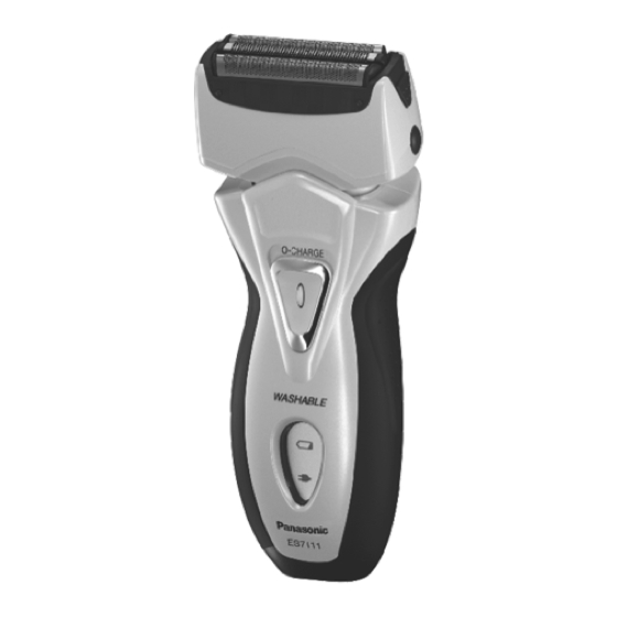
Rechargeable Shaver
ES7111
ES7112
ES7115
PAGE
Advertisement

Summary of Contents for Panasonic ES7111
-
Page 1: Table Of Contents
Order Number SD0709A55CE Rechargeable Shaver ES7111 Model No. ES7112 ES7115 Asia TABLE OF CONTENTS PAGE PAGE 1 Warning -------------------------------------------------------------- 2 2 Specifications ----------------------------------------------------- 2 3 Troubleshooting Guide ----------------------------------------- 3 4 Disassembly and Assembly Instructions ---------------- 5 5 Wiring Connection Diagram ---------------------------------12... -
Page 2: Warning
1 Warning Caution: • Pb free solder has a higher melting point that standard solder; Typicall the melting point is 50 - 70°F (30 - 40°C) higher. Please use a soldering iron with temperature control and adjust it to 750 ± 20°F (400 ± 10°C). In case of using high temperature solder- ing iron, please be careful not to heat too long. -
Page 3: Troubleshooting Guide
3 Troubleshooting Guide 3.1. Main unit and charging adaptor... - Page 4 3.2. Drying/Charging stand (ES7115 only) 3.3. Operation of Drying/charging stand (ES7115 only)
-
Page 5: Disassembly And Assembly Instructions
4 Disassembly and Assembly Instructions 4.1. Disassembly Instructions Follow the procedure below to disassemble the main unit. 1. Remove the cap, the outer foil with foil frame and the inner blade. 2. Slide the trimmer handle up to open the trimmer and unhook the trimmer handle by inserting something like a slotted screwdriver or plastic spatula into a slit. - Page 6 4. To remove the trimmer driving bar or the slit blade driving bar, press bars outward. 5. Loosen a screw and remove the bottom cover. 6. To remove the side panels, insert a small slotted screw- driver into the middle of housing and unhook.
- Page 7 7. Insert a slotted screwdriver into the space between the front panel and housing. Unhook the front panel by lifting the screwdriver up. 8. Loosen four screws on both front and back side of hous- ing. 9. Take out the housing B.
- Page 8 10. And take out the battery assembly from housing A. 11. Remove the motor assembly and tube holder. 12. Remove the battery o-ring and washer in each battery. Take out the rechargeable batteries from the chassis.
- Page 9 4.2. Cautions in Assembly NOTE: When reassembling, replace the new waterproof rubber. Make sure whether there is NO foreign substance sticking around a part covered with water seal. 4.2.1. Motor Insert the tube into the projection of the housing A and set the tube holder firmly.
- Page 10 4.2.3. Rechargeable batteries Insert the rechargeable batteries into chassis. Attach the bat- tery o-ring and washer to the battery. Put the battery assembly from the battery terminal side into housing A, and insert the motor side into housing A. NOTE: While setting the battery assembly, pull the lead wires out in order to prevent pinching.
- Page 11 4.2.5. Side panel Set the side panel on the body and insert the projection on top of side panel into the housing first. Then hook the front side and the rear side of the side panel in order. NOTE: Make sure that the left and right side panels are firmly fitted on both rear and front side.
-
Page 12: Wiring Connection Diagram
5 Wiring Connection Diagram... -
Page 13: Schematic Diagram
6 Schematic Diagram 6.1. ES7111 6.2. ES7102 6.3. ES7115... -
Page 14: Exploded View And Replacement Parts List
7 Exploded View and Replacement Parts List Model No. : ES7111/ES7112 Exploded View for ES7111/ES7112... - Page 15 Model No. : ES7111/ES7112 Parts List Ref. Safety Part No. Part Name & Description Q'ty Remarks ES7111 WES8044X7158 PROTECTIVE CAP 1 [BG] WES9085E OUTER FOIL WES7111W0048 OUTER FOIL FRAME 1 [BG] WES9064EP INNER BLADE WES7111L1008 MOTOR ASSEMBLY 1 [BG] WES7047H3268...
- Page 16 Model No. : ES7111/ES7112 Parts List Ref. Safety Part No. Part Name & Description Q'ty Remarks WES7111L1007 MOTOR ASSEMBLY 1 [BG] WES7047H3268 FOIL RELEASE BUTTON 2 (2PCS/PK), [BG] WES7046L1087 TRIMMER DRIVING BAR 1 [BG] WES7046L1077 SLIT BLADE DRIVING BAR 1 [BG]...
- Page 17 Model No. : ES7115 Exploded View for ES7115...
- Page 18 Model No. : ES7115 Parts List Ref. Safety Part No. Part Name & Description Q'ty Remarks ES7115 WES8044X7158 PROTECTIVE CAP 1 [BG] WES9085E OUTER FOIL WES7115S0047 OUTER FOIL FRAME 1 [BG] WES9064EP INNER BLADE WES7115L1007 MOTOR ASSEMBLY 1 [BG] WES7047H3268 FOIL RELEASE BUTTON 2 (2PCS/PK), [BG] WES7046L1087...


