Panasonic FP7 User Manual
Analog cassette
Hide thumbs
Also See for FP7:
- Command reference manual (1222 pages) ,
- User manual (275 pages) ,
- Additional functions manual (45 pages)
Table of Contents
Advertisement
Quick Links
WUME-FP7FCA-02
2022.11
panasonic.net/id/pidsx/global
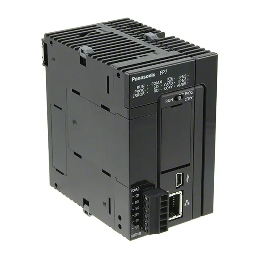
Programmable Controller
FP7 Analog Cassette
User's Manual
Supported models
FP7 Extension Cassette (Function Cassette)
● Analog I/O Cassette (Product no.
AFP7FCRA21)
● Analog Input Cassette (Product no.
AFP7FCRAD2)
● Thermocouple Input Cassette (Product no.
AFP7FCRTC2)
Advertisement
Table of Contents

Related Manuals for Panasonic FP7


Summary of Contents for Panasonic FP7
- Page 1 Programmable Controller FP7 Analog Cassette User's Manual Supported models FP7 Extension Cassette (Function Cassette) ● Analog I/O Cassette (Product no. AFP7FCRA21) ● Analog Input Cassette (Product no. AFP7FCRAD2) ● Thermocouple Input Cassette (Product no. AFP7FCRTC2) WUME-FP7FCA-02 2022.11 panasonic.net/id/pidsx/global...
- Page 2 (MEMO) WUME-FP7FCA-02...
- Page 3 Types of Manual ● There are different types of user’s manual for the FP7 series, as listed below. Please refer to a relevant manual for the unit and purpose of your use. ● The manuals can be downloaded from our Download Center: https:// industrial.panasonic.com/ac/e/dl_center/.
- Page 4 Unit name or purpose of Manual name Manual code FP7 Pulse Output Unit FP7 Pulse Output Unit User’s Manual WUME-FP7PG FP7 Positioning Unit FP7 Positioning Unit User’s Manual WUME-FP7POSP FP7 Serial Communication FP7 Series User’s Manual (SCU Communication) WUME-FP7COM Unit FP7 Multi-wire Link Unit FP7 Multi-wire Link Unit User’s Manual...
- Page 5 ● This product was developed and manufactured for use in industrial environments. Copyright / Trademarks ● The copyright of this manual is owned by Panasonic Industrial Devices SUNX Co., Ltd ● Unauthorized reproduction of this manual is strictly prohibited. ● Windows is a registered trademark of Microsoft Corporation in the U.S. and other countries.
- Page 6 AFP7CCRS1、AFP7CCRS2、AFP7CCRM1、AFP7CCRM2、AFP7CCRS1M1、 AFP7CCRET1、AFP7FCRA21、AFP7FCRAD2、AFP7FCRTC2 ● Each FP7 unit can be connected to the CPU unit of a new or old model. ● Firmware version upgrades for the CPU unit are available for both new and old models. ● When attaching expansion cassettes to the FP7CPU unit, please use only old models, or only new models.
-
Page 7: Table Of Contents
Table of Contents 1 Unit Functions and Restrictions............1-1 1.1 Unit Functions and How They Work ...........1-2 1.1.1 Functions of Cassettes ..............1-2 1.1.2 Types and Model Numbers of Cassettes ......... 1-2 1.2 Restrictions on Combinations of Units ..........1-3 1.2.1 Restrictions on Power Consumption ..........1-3 1.2.2 Applicable Versions of Unit and Software ........ - Page 8 (MEMO) viii WUME-FP7FCA-02...
-
Page 9: Unit Functions And Restrictions
1 Unit Functions and Restrictions 1.1 Unit Functions and How They Work ...........1-2 1.1.1 Functions of Cassettes ..............1-2 1.1.2 Types and Model Numbers of Cassettes ......... 1-2 1.2 Restrictions on Combinations of Units ..........1-3 1.2.1 Restrictions on Power Consumption ..........1-3 1.2.2 Applicable Versions of Unit and Software ........ -
Page 10: Unit Functions And How They Work
(K8000) so that you can determine the situation is not normal. 1.1.2 Types and Model Numbers of Cassettes Name Model No. Analog I/O cassette 2-ch Input, 1-ch output AFP7FCRA21 FP7 Extension Analog input cassette 2-ch input AFP7FCRAD2 Cassette (Function Cassette) Thermocouple Input... -
Page 11: Restrictions On Combinations Of Units
Cassette 1.2.2 Applicable Versions of Unit and Software For using the above function cassettes, the following versions of unit and software are required. Items Applicable version FP7 CPU Unit Ver.2.0 or later Programming tool software Ver.2.0 or later FPWIN GR7 1.2.3 Restrictions on the Combination of Extension Cassettes... - Page 12 (MEMO) WUME-FP7FCA-02...
-
Page 13: Specifications
2 Specifications 2.1 Analog I/O Cassette and Analog Input Cassette ........2-2 2.1.1 Input Specifications (AFP7FCRA21 / AFP7FCRAD2) ..... 2-2 2.1.2 Output Specifications (AFP7FCRA21) ..........2-3 2.1.3 Switch Settings ................2-3 2.1.4 Wiring ....................2-4 2.1.5 Input Conversion Characteristics (AFP7FCRA21 / AFP7FCRAD2) 2-6 2.1.6 Output Conversion Characteristics (AFP7FCRA21) ...... -
Page 14: Analog I/O Cassette And Analog Input Cassette
2.1 Analog I/O Cassette and Analog Input Cassette 2.1 Analog I/O Cassette and Analog Input Cassette 2.1.1 Input Specifications (AFP7FCRA21 / AFP7FCRAD2) ■ Input specifications Items Description No. of input points 2 channels (non-insulated between channels) Voltage 0-10 V, 0-5 V (Can be set individually. Switchable) Input range Current 0-20 mA... -
Page 15: Output Specifications (Afp7Fcra21)
2.1 Analog I/O Cassette and Analog Input Cassette 2.1.2 Output Specifications (AFP7FCRA21) ■ Output specifications Items Description No. of output points 1 channel/cassette Voltage 0 – 10 V, 0 – 5 V (Switchable) Output range Current 0 – 20 mA Digital value K0 - K4000 Resolution... -
Page 16: Wiring
2.1 Analog I/O Cassette and Analog Input Cassette (Note 1) When using it as analog current output, it works in either case, regardless of the setting of the switches. ■ Range selection switches (AFP7FCRAD2) SW No. Name Voltage / Current input 10 V 0 to +10 V CH0 input range selection switch... - Page 17 2.1 Analog I/O Cassette and Analog Input Cassette ● On the output circuit, a voltage amplifier and a current amplifier is connected in parallel to one D/A converter IC. Do not connect an analog device to the voltage output terminal and current output terminal of the same channel simultaneously.
-
Page 18: Input Conversion Characteristics (Afp7Fcra21 / Afp7Fcrad2)
2.1 Analog I/O Cassette and Analog Input Cassette 2.1.5 Input Conversion Characteristics (AFP7FCRA21 / AFP7FCRAD2) ■ 0V to 10V DC input Conversion characteristics graph Table of A/D converted values Input voltage (V) Digital value 1600 2400 3200 10.0 4000 When exceeding the rated range Input voltage (V) A/D converted value 0 V or less (Negative value) -
Page 19: Output Conversion Characteristics (Afp7Fcra21)
2.1 Analog I/O Cassette and Analog Input Cassette ■ 0mA to 20mA DC input Conversion characteristics graph Table of A/D converted values Input current (mA) Digital value 1000 10.0 2000 15.0 3000 20.0 4000 When exceeding the rated range Input current (mA) Digital value 0 mA or less (Negative value) - Page 20 2.1 Analog I/O Cassette and Analog Input Cassette ■ 0V to 5V DC output Conversion characteristics graph Table of D/A converted values Digital value Output voltage (V) 1600 2400 3200 4000 When exceeding the rated range Digital input value Output voltage (V) (Note 1) Negative value 4001 or more...
-
Page 21: Thermocouple Input Cassette
2.2 Thermocouple Input Cassette 2.2 Thermocouple Input Cassette 2.2.1 Input Specifications (AFP7FCRTC2) ■ Input specifications Items Description No. of input points 2 channels (insulated between channels) Input range Thermocouple type K (-50.0 to 500.0°C), Thermocouple type J (-50.0 to 500.0°C) In normal condition K –... -
Page 22: Wiring
2.2 Thermocouple Input Cassette ■ Thermocouple selection switches (AFP7FCRTC2) SW No. Name Thermocouple Type J (Note CH0 thermocouple selection switch Type K Type J (Note CH1 thermocouple selection switch Type K (Note 1) For the thermocouple selection switch, the setting at the time of power-on is effective for the operation. Note the setting will not be updated even if the switch is changed during the operation. -
Page 23: Input Conversion Characteristics
2.2 Thermocouple Input Cassette 2.2.4 Input Conversion Characteristics ■ Range of Thermocouples type K and J Conversion characteristics graph Table of A/D converted values Temperature Digital value -50.1 -501 -500 5000 500.1 5001 When exceeding the rated range Temperature Digital value -50.1°C or less K -501 500.1°C or more... - Page 24 (MEMO) 2-12 WUME-FP7FCA-02...
-
Page 25: O Allocation And Programs
3 I/O Allocation and Programs 3.1 I/O Allocation..................3-2 3.1.1 I/O Allocation..................3-2 3.2 Sample Programs ................3-3 3.2.1 Example of Analog Input/Output ............3-3 3.2.2 Example of Thermocouple Input ............3-3 WUME-FP7FCA-02... -
Page 26: I/O Allocation
3.1 I/O Allocation 3.1 I/O Allocation 3.1.1 I/O Allocation ● The I/O areas of the CPU unit are allocated to each cassette. ● An area of one word (16 points) is allocated to a channel. Input Output Description Analog I/O cassette 2-ch Input, 1-ch output Analog input cassette 2-ch input... -
Page 27: Sample Programs
3.2 Sample Programs 3.2 Sample Programs 3.2.1 Example of Analog Input/Output ● For analog input, digital conversion values are read from the device area (WX) of the input relay. ● For analog output, digital conversion values are written into the device area (WY) of the output relay. - Page 28 (MEMO) WUME-FP7FCA-02...
- Page 29 Record of Changes The manual number can be found at the bottom of the manual cover. Date Manual No. Record of Changes Dec. 2013 WUME-FP7FCA-01 1st Edition Nov. 2022 WUME-FP7FCA-02 ● Changed product type following FP7 update ● Changed manual formatting WUME-FP7FCA-02...
- Page 30 [Scope of warranty] In the event that Panasonic Industrial Devices SUNX confirms any failures or defects of the Products by reasons solely attributable to Panasonic Industrial Devices SUNX during the warranty period, Panasonic Industrial Devices SUNX shall supply the replacements of the Products, parts or replace and/or repair the defective portion by free of charge at the location where the Products were purchased or delivered to your premises as soon as possible.
- Page 31 (MEMO) WUME-FP7FCA-02...
- Page 32 Panasonic Industry Co., Ltd. Panasonic Industrial Devices SUNX Co., Ltd. https://panasonic.net/id/pidsx/global Please visit our website for inquiries and about our sales network. Panasonic Industrial Devices SUNX Co., Ltd. 2022 2022 年 11 月 WUME-FP7FCA-02...