Table of Contents
Advertisement
Quick Links
Advertisement
Table of Contents
Troubleshooting

Related Manuals for Mitsubishi Electric NZ2GF-ETB


Summary of Contents for Mitsubishi Electric NZ2GF-ETB
- Page 1 CC-Link IE Field Network Ethernet Adapter Module User's Manual -NZ2GF-ETB...
-
Page 3: Safety Precautions
SAFETY PRECAUTIONS (Read these precautions before using this product.) Before using this product, please read this manual and the relevant manuals carefully and pay full attention to safety to handle the product correctly. In this manual, the safety precautions are classified into two levels: " WARNING"... - Page 4 [Design Precautions] CAUTION ● Do not install the communication cables together with the main circuit lines or power cables. Keep a distance of 100mm or more between them. Failure to do so may result in malfunction due to noise. [Security Precautions] WARNING ●...
- Page 5 [Wiring Precautions] CAUTION ● Individually ground the FG and LG terminals of the programmable controller with a ground resistance of 100 ohms or less. Failure to do so may result in electric shock or malfunction. ● Use applicable solderless terminals and tighten them within the specified torque range. If any spade solderless terminal is used, it may be disconnected when a terminal block screw comes loose, resulting in failure.
- Page 6 [Startup and Maintenance Precautions] WARNING ● Do not touch any terminal while power is on. Doing so will cause electric shock or malfunction. ● Shut off the external power supply (all phases) used in the system before cleaning the module or retightening the terminal block screws.
-
Page 7: Conditions Of Use For The Product
Notwithstanding the above restrictions, Mitsubishi Electric may in its sole discretion, authorize use of the PRODUCT in one or more of the Prohibited Applications, provided that the usage of the PRODUCT is limited only for the specific applications agreed to by Mitsubishi Electric and provided further that no special quality assurance or fail-safe, redundant or other safety features which exceed the general specifications of the PRODUCTs are required. -
Page 8: Introduction
INTRODUCTION Thank you for purchasing the CC-Link IE Field Network Ethernet adapter module (hereinafter abbreviated as the Ethernet adapter module). This manual describes the operating procedure, system configuration, parameter setting, functions, and troubleshooting of the Ethernet adapter module. Before using this product, please read this manual and the relevant manuals carefully and develop familiarity with the functions and performance of the Ethernet adapter module to handle it correctly. -
Page 9: Relevant Manuals
RELEVANT MANUALS (1) CC-Link IE Field Network (relevant) manuals When using the CC-Link IE Field Network for the first time, refer to the CC-Link IE Field Network Master/Local Module User's Manual first. The following shows the structure of the CC-Link IE Field Network manuals. Manual name Description <manual number (model code)>... -
Page 10: Table Of Contents
CONTENTS CONTENTS SAFETY PRECAUTIONS ............. 1 CONDITIONS OF USE FOR THE PRODUCT . - Page 11 Wiring ..............61 6.4.1 Wiring of the power supply part .
- Page 12 9.3.2 The LEDs on the CC-Link IE Field Network part ........148 9.3.3 The LEDs on the Ethernet part .
- Page 13 Appendix 6 Resetting Parameters to Factory Default Values ......229 Appendix 7 Access Codes and an Attribute Code ........230 Appendix 8 EMC and Low Voltage Directives .
-
Page 14: Manual Page Organization
MANUAL PAGE ORGANIZATION In this manual, pages are organized and the symbols are used as shown below. The following illustration is for explanation purpose only, and should not be referred to as an actual documentation. "" is used for screen names and items. The chapter of the current page is shown. -
Page 15: Terms
A process of stopping data link if a data link error occurs Ethernet adapter module The abbreviation for the NZ2GF-ETB CC-Link IE Field Network Ethernet adapter module External device A generic term for devices that send SLMP request messages to an Ethernet adapter module... - Page 16 Term Description Reserved station A station reserved for future use. This station is not actually connected, but counted as a connected station Response message An SLMP message sent from an Ethernet adapter module to an external device Return A process of restarting data link when a station recovers from an error The abbreviation for JP.RIRD and GP.RIRD.
-
Page 17: Packing List
PACKING LIST The following items are included in the package of this product. Before use, check that all the items are included. NZ2GF-ETB Ethernet adapter module Safety Guidelines (IB-0800463) -
Page 18: Chapter 1 Ethernet Adapter Module
CHAPTER 1 ETHERNET ADAPTER MODULE The Ethernet adapter module connects external devices on the Ethernet network to CC-Link IE Field Network. For details on CC-Link IE Field Network, refer to the following. User's manual for the master/local module used Ethernet adapter module CC-Link IE Field Network... - Page 19 CHAPTER 1 ETHERNET ADAPTER MODULE (1) Communication using SLMP (a) Data of the programmable controller device can be read/written Device data can be read or written from an external device to a module on the network where the Ethernet adapter module is connected. Data reading and writing is also available to the devices of the Ethernet adapter module.
- Page 20 (2) Connection of MC protocol devices The message format of SLMP is the same as that of the QnA compatible 3E or 4E frame format of the MC protocol. Therefore, external devices that support the MC protocol can be connected to CC-Link IE Field Network.
- Page 21 CHAPTER 1 ETHERNET ADAPTER MODULE The IP packet transfer function allows an IP packet to be transferred from an external device to a request destination. An Ethernet adapter module cannot be used as a request source or a request destination. (4) Connection to MELSOFT products or GOTs The Ethernet adapter module can be also connected to MELSOFT products or GOTs.
- Page 22 (6) Transient transmission Transient transmission allows direct access from a master or local station to the devices or buffer memory of the Ethernet adapter module. Requests from the master or local station to the Ethernet adapter module are made with dedicated instructions. (...
- Page 23 CHAPTER 1 ETHERNET ADAPTER MODULE (8) Diagnostics (a) CC-Link IE Field Network diagnostics By connecting GX Works2 to a master/local module, the condition of the entire CC-Link IE Field Network can be viewed on the CC-Link IE Field Network diagnostics dialog box. ( User's manual for the master/local module used) The status of the entire CC-Link IE Field Network can be monitored.
-
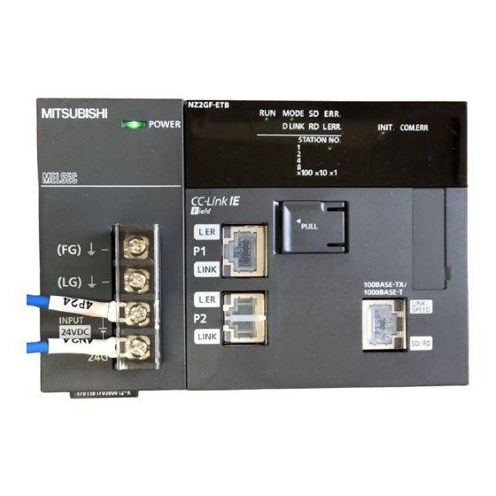
Page 24: Chapter 2 Part Names
CHAPTER 2 PART NAMES This chapter describes the Ethernet adapter module parts and their names. Name Description Power is supplied to the Ethernet adapter module through this part. (24VDC) Power supply part ( Page 23, Section 2.1) The Ethernet adapter module is connected to CC-Link IE Field Network at this part. •... -
Page 25: Power Supply Part
CHAPTER 2 PART NAMES Power Supply Part Respective names of the Ethernet adapter module's power supply part are shown below. Name Part Indicates the operating status of the power supply part. POWER LED • On (green): Normally operating. • Off: No power input, power failure, or hardware failure FG terminal A ground terminal connected to the shield pattern on the printed circuit board (M3.5 screws) LG terminal... -
Page 26: Cc-Link Ie Field Network Part
CC-Link IE Field Network Part Respective names of the Ethernet adapter module's CC-Link IE Field Network part are shown below. (1) LEDs Name Description Indicates the operating status. On: Normally operating. (RUN status) Flashing: Normally operating. (STOP status) • The Ethernet adapter module's switch is set to STOP. (Data transfer among the Ethernet adapter module devices is RUN LED stopped.) •... - Page 27 CHAPTER 2 PART NAMES Name Description Indicates the error status of the Ethernet adapter module. The error details can be checked by the CC-Link IE Field Network diagnostics. ( Page 144, Section 9.2.1) On: One of the following errors occurred in the Ethernet adapter module. •...
- Page 28 (2) Switch With this switch, the operation of the Ethernet adapter module can be controlled. Name Description The Ethernet adapter module can be reset by the following method. Set the switch with your fingertip. Using a tool such as a screwdriver may damage the switch. Shift the switch to RESET/TEST for one second or longer.
- Page 29 CHAPTER 2 PART NAMES (3) Connectors Name Description The PORT1 connector for connecting to CC-Link IE Field Network. (RJ45 connector) Connect an Ethernet cable to this. ( Page 63, Section 6.4.2) There are no restrictions on the connection order of the cables for the "P1" and "P2" connectors. •...
-
Page 30: Ethernet Part
Ethernet Part This section describes the names of the Ethernet adapter module's Ethernet part. Do not remove this sticker since it is used for maintenance. Name Description Indicates the initial processing status. INIT. LED On: Initial processing completed. Off: Initial processing not completed. Indicates the Ethernet communication status. -
Page 31: Chapter 3 Specifications
CHAPTER 3 SPECIFICATIONS CHAPTER 3 SPECIFICATIONS This chapter describes the specifications of the Ethernet adapter module. General Specifications Item Specification Operating ambient 0 to 55 temperature Storage ambient -25 to 75 temperature Operating ambient humidity 5 to 95%RH, non-condensing Storage ambient humidity Constant Frequency... -
Page 32: Performance Specifications
Performance Specifications The following describes the performance specifications of the Ethernet adapter module. Item Specification 8192 points, 1KB (X0 to X1FFF are assigned to RX0 to RX1FFF.) 8192 points, 1KB (Y0 to Y1FFF are assigned to RY0 to RY1FFF.) 8192 points, 16KB (1024 points of W0 to W3FF are assigned to RWw0 to RWw3FF. 1024 points of W1000 to W13FF are assigned to RWr0 to RWr3FF.) Number of device points... -
Page 33: Performance Specifications Of Each Part
CHAPTER 3 SPECIFICATIONS 3.2.1 Performance specifications of each part The performance specifications of each part of the Ethernet adapter module are described below. CC-Link IE Power supply part Field Network part Ethernet part (1) Power supply part Item Specification Input voltage ( Page 32, Section 3.2.1 (1) (a)) 24VDC (-35% to +30%) Current consumption 0.6A... - Page 34 (a) Input voltage Input voltage is a voltage at which the power supply part operates normally. If it is outside the specified range, the Ethernet adapter module may detect an error and stop its operation. (b) Inrush current Inrush current is a large current that instantaneously flows into a circuit immediately after power is applied. Reapplying input power after power-off may cause an inrush current that exceeds the specified value.
- Page 35 CHAPTER 3 SPECIFICATIONS (2) CC-Link IE Field Network part Item Specification 8192 points, 16KB 8192 points, 16KB Maximum link points per network 16384 points, 2KB 16384 points, 2KB 1024 points, 2KB 1024 points, 2KB Maximum link points per station 2048 points, 256 bytes 2048 points, 256 bytes Station type Intelligent device station...
- Page 36 (3) Ethernet part Item Specification For users Number of For auto-open connections For MELSOFT 3 (TCP connection: 1 , UDP connection: 1, Direct connection: 1) connection 1025 to 4999, 5011 to 65534 (0401 to 1387 , 1393 to FFFE Own Station Port No. Number of simultaneously connectable Up to 32 modules...
- Page 37 CHAPTER 3 SPECIFICATIONS (4) Communication specifications for TCP connection (a) Number of resends and resend interval If the Ethernet adapter module sent a message to an external device and after that did not receive an ACK from the external device, it will resend the message at the intervals shown below. Item Specification Number of resends...
-
Page 38: List Of The Functions
List of the Functions This section lists the functions of the Ethernet adapter module. (1) Communications with an external device Function Refer to Description Device data can be read or written from an external device to a Communications module on the network where the Ethernet adapter module is from an external Page 68, Section 7.1 connected. -
Page 39: Buffer Memory List
CHAPTER 3 SPECIFICATIONS Buffer Memory List The buffer memory is used for exchanging data between the Ethernet adapter module and a master/local module or an external device. The contents of the buffer memory return to the default state (initial values) when the system is powered off or reset. Address Initial (Decimal... - Page 40 Address Initial (Decimal Name Read/Write Refer to value (Hexadecimal)) Mode Read Page 208, Network No. Read Appendix 1.2 Own station information Station No. Read (Parameters) 39 to 47 System area to 2F Page 208, 0001 Read Appendix 1.2 Function check area 49 to 767 ...
- Page 41 CHAPTER 3 SPECIFICATIONS Address Initial (Decimal Name Read/Write Refer to value (Hexadecimal)) 1296 Open system (510 1297 Protocol Page 210, (511 Read Appendix 1.3 1298 Communication data code (512 1299 1388 Own Station Port No. (513 1300 System area (514 Ethernet port operation area...
- Page 42 Address Initial (Decimal Name Read/Write Refer to value (Hexadecimal)) 1328 Open system (530 1329 Protocol (531 1330 Communication data code Page 212, (532 Read Appendix 1.3 1331 138A Own Station Port No. (533 1332 Ethernet port operation area TCP connection system (534 (MELSOFT application communication port (TCP/IP) area...
- Page 43 CHAPTER 3 SPECIFICATIONS Address Initial (Decimal Name Read/Write Refer to value (Hexadecimal)) 1360 Open system (550 1361 Protocol Page 214, (551 Read Appendix 1.3 1362 Communication data code (552 1363 1392 Own Station Port No. (553 1364 System area (554 Ethernet port operation area...
- Page 44 Address Initial (Decimal Name Read/Write Refer to value (Hexadecimal)) 2064 Error code (810 2065 Connection No. (811 2066 Open system Page 215, (812 Read Appendix 1.4 2067 Protocol (813 2068 Own Station Port No. (814 2069 Ethernet port error log area (Error Destination port No.
- Page 45 CHAPTER 3 SPECIFICATIONS Address Initial (Decimal Name Read/Write Refer to value (Hexadecimal)) Page 93, 5632 Send request flag Read/Write Section 7.2.5 (1600 Page 93, 5633 Send completed flag Read Section 7.2.5 (1601 Page 93, On-demand function data sending 5634 Completion code Read Section 7.2.5 area...
-
Page 46: Slmp
SLMP The Ethernet adapter module's devices can be read or written with command messages in the predefined format from an external device. For details on SLMP, refer to the following. SLMP Reference Manual 3.5.1 Available command list The following table lists the commands that can be executed from an external device to the Ethernet adapter module. The ... -
Page 47: Ranges Of Accessible Devices And Buffer Memory
CHAPTER 3 SPECIFICATIONS 3.5.2 Ranges of accessible devices and buffer memory Within the following device and buffer memory ranges, external devices can access the Ethernet adapter module. (1) Devices Device Device No. range Unit Input 0000 to 1FFF Hexadecimal Output 0000 to 1FFF Hexadecimal Link special relay... -
Page 48: Chapter 4 Procedure Before The Operation
CHAPTER 4 PROCEDURE BEFORE THE OPERATION This chapter describes the procedure to be taken before operating the Ethernet adapter module. Start-Up Procedure The following shows how to start up the system where the Ethernet adapter module is used. Setting on the master station Set network parameters on the master station. - Page 49 CHAPTER 4 PROCEDURE BEFORE THE OPERATION Memo...
-
Page 50: Chapter 5 System Configuration
CHAPTER 5 SYSTEM CONFIGURATION This chapter describes a configuration of the system containing the Ethernet adapter module. For the overall CC-Link IE Field Network configuration, refer to the following. User's manual for the master/local module used Network Configuration The following shows a network configuration for the Ethernet adapter module. Through a switching hub, the Ethernet adapter module can communicate with up to 32 external devices at the same time. -
Page 51: Network Components
Special cables, such as flame-retardant or water-tight cables, and relay adapters are also available. Please consult your local Mitsubishi Electric System & Service Co., Ltd. ● For order or inquiry on the cables: Mitsubishi Electric System & Service Co., Ltd. www.melsc.co.jp/business... - Page 52 • Compliant with the IEEE802.3(1000BASE-T/100BASE-TX) standard • Supporting the auto MDI/MDI-X function • Supporting the auto-negotiation function • Switching hub (layer 2 switch) Repeater hubs cannot be used. (a) Mitsubishi Electric products Type Model Data communication rate NZ2EHG-T8 1000Mbps/100Mbps/10Mbps...
-
Page 53: Applicable Systems
CHAPTER 5 SYSTEM CONFIGURATION Applicable Systems 5.3.1 Configuration tool (1) Operating environment The following table lists the operating environment of the personal computer where the configuration tool is used. (a) Computer requirements Item Description Personal computer running any of the following operating systems ... - Page 54 (b) Precautions on the operating systems • The 64-bit Windows XP Professional, Windows Vista , and Windows 7 cannot be used. • When the logon user right is Guest, the operating systems cannot be used. • When Windows Firewall settings are enabled, direct connection may not function properly.
-
Page 55: Software Package
CHAPTER 5 SYSTEM CONFIGURATION 5.3.2 Software package GX Works2 allows the status check of the Ethernet adapter module and access to other stations. GX Developer cannot be used. Software Version GX Works2 Version 1.40S (1) Precaution If a GX Works2 version earlier than the above is used, the dialog box will not be displayed correctly. -
Page 56: Chapter 6 Installation And Wiring
CHAPTER 6 INSTALLATION AND WIRING This chapter explains installation of the Ethernet adapter module and the wiring method. Installation Environment Install the Ethernet adapter module in an environment that meets the general specifications. ( Page 29, Section 3.1) Do not install the Ethernet adapter module in the place where: •... -
Page 57: Installation
CHAPTER 6 INSTALLATION AND WIRING Installation When installing the Ethernet adapter module to a control panel or any other place, consider the operability, maintainability, and environmental resistance. 6.2.1 Installation precautions (1) Do not directly touch any conductive parts and electronic components of the Ethernet adapter module. -
Page 58: Mounting The Modules On A Din Rail
6.2.3 Mounting the modules on a DIN rail The Ethernet adapter module must be mounted on a DIN rail. The procedure for mounting the Ethernet adapter module on a DIN rail is shown below. (1) Mounting procedure Pull down all of the DIN rail hooks on the back of the Ethernet adapter module. - Page 59 CHAPTER 6 INSTALLATION AND WIRING Hitch the bottom hook of the DIN rail stopper to the bottom of the DIN rail. Hitch the hook according to the orientation of the arrow on the front of the stopper. Hitch the hook to bottom of the DIN rail Hitch the upper hook of the DIN rail stopper to the top of the DIN rail.
- Page 60 (2) Removal procedure The Ethernet adapter module can be removed from the DIN rail in reverse order of the mounting procedure. (3) Applicable DIN rail models (IEC 60715) • TH35-7.5Fe • TH35-7.5Al • TH35-15Fe (4) DIN rail stopper Use stoppers that can be attached to the DIN rail. (5) Interval between DIN rail mounting screws To ensure the strength of the DIN rail, tighten DIN rail mounting screws (sold separately) 30mm away from the both edges of the DIN rail and at intervals of 200mm or less.
-
Page 61: Testing The Module Before Wiring
CHAPTER 6 INSTALLATION AND WIRING Testing the Module Before Wiring (1) Unit test Perform a unit test to check the Ethernet adapter module for hardware failure. Turn off the power. Connect PORT1 and PORT2 of the Ethernet adapter module with an Ethernet cable. Ethernet cable Turn on the power. - Page 62 When the unit test is completed, flashing of the When completed 1 and 10 LEDs is stopped, and the D LINK LED turns on. : On • When completed: The D LINK LED turns on with the : Flashing ERR. LED off. •...
-
Page 63: Wiring
CHAPTER 6 INSTALLATION AND WIRING Wiring 6.4.1 Wiring of the power supply part (1) Wiring method The following figure shows an example of wiring to the power supply part. 24V DC NZ2GF-ETB INPUT +24V Ground wire Grounding... - Page 64 (2) Precautions Take the following precautions when wiring the power supply. • Considering the rated current and inrush current of the power supply part, connect a circuit breaker having an appropriate sensing property or an external fuse causing proper blowout. (A 10A circuit breaker or external fuse is recommended.) •...
-
Page 65: Ethernet Cable Wiring
CHAPTER 6 INSTALLATION AND WIRING 6.4.2 Ethernet cable wiring The following figure shows the respective ports connected to CC-Link IE Field Network and Ethernet. Connected to CC-Link Connected to Ethernet IE Field Network... - Page 66 (1) Connecting the Ethernet cable For Ethernet cables, refer to "Network Components". ( Page 49, Section 5.2.2 (1)) (a) Connection Turn off the power. Insert the Ethernet cable connector into the port until a click sound is heard. Pay attention to the orientation of the connector.
- Page 67 CHAPTER 6 INSTALLATION AND WIRING (b) Disconnection Turn off the power. Pull out the Ethernet cable while pinching the retaining clip on the connector. There is no need to distinguish between PORT1 and PORT2. • When using only one port in a star topology, either of PORT1 or PORT2 can be used. Either port can be used.
-
Page 68: Grounding
6.4.3 Grounding Observe the following: • Provide independent grounding when possible. Ground the FG and LG terminals to the protective ground conductor. (Grounding resistance: 100 or less) • If independent grounding is not possible, employ shared grounding, making all of the ground wires to the same length. -
Page 69: Precautions
CHAPTER 6 INSTALLATION AND WIRING 6.4.4 Precautions This section provides precautions for wiring to CC-Link IE Field Network and Ethernet. (1) Ethernet cables Use Ethernet cables that satisfy the 1000BASE-T or 100BASE-TX standard. ( Page 49, Section 5.2.2 (1)) (2) Laying Ethernet cables •... -
Page 70: Chapter 7 Communication Of The Ethernet Adapter Module
Communication examples of SLMP communication and cyclic transmission are given below. 7.1.1 System configuration The following system configuration is used as an example. Ethernet adapter module (NZ2GF-ETB) Power supply module (Q62P) IP address: 192.168.3.30 CPU module (Q10UDHCPU) Subnet mask: 255.255.255.0 Master/local module (QJ71GF11-T2) Port No.: 2000... -
Page 71: Communication Details
CHAPTER 7 COMMUNICATION OF THE ETHERNET ADAPTER MODULE 7.1.2 Communication details The following SLMP message is sent from the external device to the Ethernet adapter module. • By Read (command: 0401), 32-bit data in RY0000 to RY001F (Y0000 to Y001F) are read out. •... - Page 72 (3) Link device assignment (a) Assignment of RX and RY Master station Master/local CPU module Ethernet adapter module module 0000 0000 0000 0000 1000 03FF 03FF 03FF 13FF (Unused) (Unused) 1FFF 1FFF SLMP 0000 0000 0000 0000 Reading 03FF 1000 03FF 03FF data of 32 bits...
-
Page 73: Network Setting On The Configuration Computer
CHAPTER 7 COMMUNICATION OF THE ETHERNET ADAPTER MODULE 7.1.3 Network setting on the configuration computer Open the "Internet Protocol (TCP/IP) Properties" dialog box on the personal computer, and configure the settings as shown below. Control panel "Network and Internet Connections" "Network Connections" "Local Area Connection"... - Page 74 Open the "Internet Options" dialog box from the Web browser, and select "Local Intranet Zone" as shown below. Web browser [Tools] [Internet Options] "Security" Select "Local intranet". After that, click the [Custom level...] button and configure the settings as shown below. Select "Enable"...
-
Page 75: Connection To Cc-Link Ie Field Network
CHAPTER 7 COMMUNICATION OF THE ETHERNET ADAPTER MODULE 7.1.4 Connection to CC-Link IE Field Network (1) Setting in the master station Use GX Works2 to set the parameters in the master station. Use the default settings for the parameters other than those set below. - Page 76 Click the [Network Configuration Settings] button to set the parameters as follows. After setting, click the [End] button. Click the [Refresh Parameters] button to open the refresh parameter setting window. Set the parameters as follows. After setting, click the [End] button. In the network parameter setting window, click the [End] button.
- Page 77 Start up the configuration tool using a Web browser. ( Page 184, Section 10.1.2) Open the "Parameter Setting" dialog box in the configuration tool to set the parameters as follows. Setting item tree NZ2GF-ETB [Parameter] "CC-Link IE Field Network" After setting, click the [End] button.
- Page 78 Write the set parameters to the Ethernet adapter module. (Set the switch on the Ethernet adapter module to STOP.) [Online] [Write] Click The following dialog box appears. Click Set the switch on the Ethernet adapter module to RUN.
- Page 79 CHAPTER 7 COMMUNICATION OF THE ETHERNET ADAPTER MODULE (3) Checking the connection After setting the parameters for the master station and the Ethernet adapter module, check if data link can be normally performed between them, by using the CC-Link IE Field Network diagnostics of GX Works2 connected to the master station.
-
Page 80: Connection To Ethernet
Start up the configuration tool using a Web browser. ( Page 184, Section 10.1.2) Open the "Parameter Setting" dialog box in the configuration tool to set the parameters as follows. Setting item tree NZ2GF-ETB [Parameter] "Ethernet" Click the [Connection Setting] button to display the "Ethernet Port Connection Setting" window. - Page 81 CHAPTER 7 COMMUNICATION OF THE ETHERNET ADAPTER MODULE Click the [Detail Setting] button to display the "Detail Setting" dialog box. Set the parameters as follows. Click the [End] button. In the "Ethernet Port Connection Setting" window, click the [End] button. In the "Parameter Setting"...
- Page 82 The following dialog box is displayed. Click Set the switch on the Ethernet adapter module to RUN.
- Page 83 This is a sample program for testing a connection between the Ethernet adapter module and the external device. This program reads RY0000 to RY001F of the Ethernet adapter module **/ and writes data to RWr0000 and RWr0001. Copyright(C) 2010 Mitsubishi Electric Corporation All Rights Reserved /***********************************************************************************************/ #include <winsock2.h>...
- Page 84 // Definitions for checking the receiving data size #define SEND_REQ_1 25 // The size of the request message to be sent for device writing (3E frame, binary) #define RECV_ANS_1 11 // The size of the response message to be received for device writing (3E frame, binary) #define SEND_REQ_2 21 // The size of the request message to be sent for device reading (3E frame, binary) #define RECV_ANS_2 15...
- Page 85 CHAPTER 7 COMMUNICATION OF THE ETHERNET ADAPTER MODULE hostdata.sin_family = AF_INET; hostdata.sin_port = sc.my_port; hostdata.sin_addr.s_addr = sc.my_addr.s_addr; if(bind(socketno, (LPSOCKADDR)&hostdata, sizeof(hostdata)) != SOCK_OK) { // Bind Sockerror(ERROR_BIND); // Error handling return (SOCK_NG); EthernetAD.sin_family = AF_INET; EthernetAD.sin_port = sc.aj_port; EthernetAD.sin_addr.s_addr = sc.aj_addr.s_addr; if(connect(socketno, (LPSOCKADDR)&EthernetAD, sizeof(EthernetAD)) != SOCK_OK) { // Connect (Active open) Sockerror(ERROR_CONNECT);...
- Page 86 if(send(socketno, (char *)(s_buf), SEND_REQ_2, 0) == SOCKET_ERROR) { // Data sending Sockerror(ERROR_SEND); // Error handling return (SOCK_NG); // Receiving data with the size checked rbuf_idx = 0; // Initializes the head index of the receive data storage recv_size = 0; // Initializes the number of receive data while(1) { length = recv(socketno, (char *)(&r_buf[rbuf_idx]), (BUF_SIZE - rbuf_idx), 0);...
- Page 87 CHAPTER 7 COMMUNICATION OF THE ETHERNET ADAPTER MODULE case 2: // Creates a frame requesting for writing to RWr0 and RWr1devices (3E frame) s_buf[0] = 0x50; // Setting subheader s_buf[1] = 0x00; s_buf[2] = 0x00; // Setting network number s_buf[3] = 0xff; // Setting station number s_buf[4] = 0xff;...
- Page 88 printf("\nRWr write completed\n"); //Write value display for (i = 0; i < 2; i++) { disp[0] = s_buf[21+(i*2)]; disp[1] = s_buf[22+(i*2)]; printf("RWr000%d written value: %4X\n", i, *(USHORT*)&disp); printf("\n\n"); break; default: k = 0; break; if(shutdown(socketno, 2) != SOCK_OK) { // Send/receive disabled Sockerror(ERROR_SHUTDOWN);...
- Page 89 CHAPTER 7 COMMUNICATION OF THE ETHERNET ADAPTER MODULE void Sockerror(int error_kind) // Error handling function if (error_kind == ERROR_INITIAL){ printf("Initial processing is abnormal."); else{ nErrorStatus = WSAGetLastError(); switch(error_kind){ case ERROR_SOCKET: printf("Failed to create the socket."); break; case ERROR_BIND: printf("Failed to bind."); break;...
- Page 90 (3) Executing the program (a) Sending the Read command On the "Device/Buffer Memory Batch Monitor" window of GX Works2, set values for Y1000 to Y100F and Y1010 to Y101F of the CPU module as shown below. [Online] [Monitor] [Device/Buffer Memory Batch] Run the executable file at the command prompt.
- Page 91 CHAPTER 7 COMMUNICATION OF THE ETHERNET ADAPTER MODULE (b) Sending the Write command Run the executable file at the command prompt. In the following window, enter 2. By the Write (command: 1401), a program of writing 2-word data (1234 , 5678 ) to RWr0000 to RWr0001 (W1000 to W1001) will be executed.
-
Page 92: Communication Using The On-Demand Function
Communication Using the On-demand Function This section provides an example of where a send request is issued from the CPU module to the Ethernet adapter module and data is sent to the external device. Check the corresponding serial No. and software version. ( Page 240, Appendix 10) To perform the on-demand function, use the REMFR and REMTO instructions. -
Page 93: Applicable Range Of On-Demand Data
CHAPTER 7 COMMUNICATION OF THE ETHERNET ADAPTER MODULE 7.2.3 Applicable range of on-demand data The on-demand function can send data only to the external devices on the same network (Ethernet) as the Ethernet adapter module. In addition, data can be simultaneously sent to all the external devices on Ethernet where the Ethernet adapter module is also connected (broadcast communications). -
Page 94: How To Send On-Demand Data
7.2.4 How to send on-demand data On-demand data is sent to an external device after the buffer memory in the Ethernet adapter module receives/sends the data from/to the CPU module using the REMFR and REMTO instructions. The Ethernet adapter module converts the data sent to the buffer memory into SLMP and sends it to the external device. -
Page 95: Buffer Memories Used For The On-Demand Function
CHAPTER 7 COMMUNICATION OF THE ETHERNET ADAPTER MODULE 7.2.5 Buffer memories used for the on-demand function This section describes the buffer memories used for channel 1 in the on-demand function. For channels 2 to 4, store information in the same way as channel 1. ( Page 37, Section 3.4) (1) Send request flag (buffer memory address: 5632 (1600 This flag requests on-demand data to be sent from the Ethernet adapter module to an external device. - Page 96 (4) Setting data (buffer memory address: 5635 to 6655 (1603 to 19FF On-demand data can be sent using the connection for users and auto-open UDP port in the Ethernet adapter module. (a) On-demand data sending using the connection for users (TCP only) Send on-demand data using the connection of the connection setting in the configuration tool.
- Page 97 CHAPTER 7 COMMUNICATION OF THE ETHERNET ADAPTER MODULE (5) Setting data (a) Connection No. Set the connection No. where on-demand data is sent from the Ethernet adapter module. Connection Setting value 1 to 32 Connection for users Auto-open UDP port If any number other than those described above is set, a connection No.
- Page 98 (e) Destination IP address (when using the auto-open UDP port) Set the IP address of the external device where on-demand data is sent from the Ethernet adapter module. The effective setting values are from 0.0.0.1 to 255.255.255.255. When 255.255.255.255 is set, on-demand data is sent to all the external devices (all the hosts) with the same network address (broadcast communications).
- Page 99 CHAPTER 7 COMMUNICATION OF THE ETHERNET ADAPTER MODULE (h) Send data (buffer memory address: 5644 to 6603 (160C to 19CB Set the data to be sent from the Ethernet adapter module to an external device. The set data is sent to the external device based on the send data format of the control data. Send data by send data format are as follows: •...
- Page 100 • When a send data format is 2 (word unit and binary code selected): This send data is used to send a device value using the binary code. SLMP on-demand data Word unit specification, Buffer memory binary code Send data format Send data Send data length Send data...
-
Page 101: On-Demand Data Format
CHAPTER 7 COMMUNICATION OF THE ETHERNET ADAPTER MODULE 7.2.6 On-demand data format This section explains about on-demand data sent from the Ethernet adapter module to an external device. (1) On-demand data The following illustration shows the on-demand format. Request Network Station destination Request data... - Page 102 (c) Request destination module I/O No., request data length, monitoring timer, command, and subcommand The following values are stored for each item: Setting item Setting value 03FF Request destination module I/O No. The data length from the monitoring timer to the send data is stored in 4-digit hexadecimal Request data length format.
- Page 103 CHAPTER 7 COMMUNICATION OF THE ETHERNET ADAPTER MODULE (3) Example of on-demand data (a) On-demand data format in SLMP (no serial No.) • ASCII data Request destination Network Station module For future Request Subheader number number I/O number extension data length Monitoring timer Command Subcommand...
- Page 104 (b) On-demand data format in SLMP (serial No. added) • ASCII data Request destination Network Station module For future Request data Subheader Serial number Fixed value number number I/O number extension length Monitoring timer Command Subcommand Send data • Binary data Subheader Request destination...
-
Page 105: Example Of On-Demand Data Sending
CHAPTER 7 COMMUNICATION OF THE ETHERNET ADAPTER MODULE 7.2.7 Example of on-demand data sending This section explains how to send on-demand data and provides a program example. (1) How to send data Follow the instructions below to send on-demand data. (a) Ethernet adapter module Connect the Ethernet adapter module to CC-Link IE Field Network and Ethernet. - Page 106 (2) Program example (a) On-demand data setting Item Specification Number of channels simultaneously used 1 channel Send data length 4 bytes Protocol Available connection Connection for users (connection No.1) Frame format SLMP (serial No. added) Communication data code setting ASCII code communication (b) Devices used for a program Device Description...
- Page 107 CHAPTER 7 COMMUNICATION OF THE ETHERNET ADAPTER MODULE (c) On-demand data to be sent Request destination Network Station module For future Request Subheader Serial number Fixed value number number I/O number extension data length Monitoring timer Command Subcommand Send data (d) Program Clear control data.
- Page 108 Set send data. REMTO instruction error output Turn on Send request flag. REMTO instruction error output Read Send completed flag and Completion code. REMFR instruction error output Check Send completed flag and transmit on-demand data. Completion output Transmit on-demand data. Error output Turn off Send request flag.
-
Page 109: Ip Communications Over Cc-Link Ie Field Network (Ip Packet Transfer Function)
CHAPTER 7 COMMUNICATION OF THE ETHERNET ADAPTER MODULE IP Communications over CC-Link IE Field Network (IP Packet Transfer Function) This section describes an example of communications using the specified IP address between external devices over CC-Link IE Field Network. Check the corresponding serial No. and software version. ( Page 240, Appendix 10) ●... -
Page 110: Deciding The Ip Address
7.3.1 Deciding the IP address This section explains how to set an IP address to perform communications over CC-Link IE Field Network. (1) When the network addresses of the request source external device, request destination external device, and modules between them are the same Communications can be performed with the minimum setting by setting the same network address of the IP address in the request source external device, request destination external device, and modules between them. - Page 111 CHAPTER 7 COMMUNICATION OF THE ETHERNET ADAPTER MODULE Set the numbers according to the range supported by the external device used. The range may not apply depending on the external device. Check the specifications of the external device used. To transmit communications to the external device, the routing parameters are required. ( Page 112, Section 7.3.4 (1))
- Page 112 (2) When the network addresses are different When the same network address cannot be set for the external device and CC-Link IE Field Network, decide the IP address within the ranges listed in the following table. Setting range of the IP address Device to be set First and second octets Third octet...
-
Page 113: System Configuration
CHAPTER 7 COMMUNICATION OF THE ETHERNET ADAPTER MODULE 7.3.2 System configuration For an example of when the request source external device, request destination external device, and modules between them have the same network address, refer to the following. Page 111, Section 7.3.2 to Page 124, Section 7.3.6 IP address 192.168.3.30 192.168.2.30... -
Page 114: Connection To Cc-Link Ie Field Network
7.3.4 Connection to CC-Link IE Field Network Set the parameters in the master station for IP communications over CC-Link IE Field Network. (1) Setting in the master station Use GX Works2 to set the parameters in the master station. Use the default settings for the parameters other than those set below. - Page 115 CHAPTER 7 COMMUNICATION OF THE ETHERNET ADAPTER MODULE Click the [Network Configuration Settings] button to set the parameters as follows. The following setting is an assignment example. (Communications using the IP packet transfer function do not affect assigned points.) Change the points according to the system configuration used. Click the [Network Operation Settings] button to set the IP address of the master station.
- Page 116 ● Set the IP address of CC-Link IE Field Network in the master station and submaster station. When the IP address is set, the IP address is automatically assigned to the CC-Link IE Field Network part on the Ethernet adapter module. The IP address to be assigned is as follows.
- Page 117 CHAPTER 7 COMMUNICATION OF THE ETHERNET ADAPTER MODULE Click the [Routing Parameters] button to set the communication route. The communication route needs to be set so that communications reach the network of the Ethernet adapter module (Ethernet part). Because Ethernet adapter modules do not have routing parameters, set the routing parameters of the master station to perform communications.
- Page 118 ● Details on the routing parameters Refer to the user’s manual for the master/local module used. ● When an external device is connected to an Ethernet adapter module Set the routing parameters so that communications transmit through the master station. Communications from an Ethernet adapter module automatically transmit through the master station.
- Page 119 CHAPTER 7 COMMUNICATION OF THE ETHERNET ADAPTER MODULE After setting, click the [End] button. Write the set parameters to the CPU module on the master station. [Online] [Write to PLC] Reset the CPU module or power off and on the system. RESET or Power OFF...
- Page 120 Start up the configuration tool using a Web browser. ( Page 184, Section 10.1.2) Open the "Parameter Setting" dialog box in the configuration tool to set the parameters as follows. Setting item tree NZ2GF-ETB [Parameter] "CC-Link IE Field Network" • Setting on the request source •...
- Page 121 CHAPTER 7 COMMUNICATION OF THE ETHERNET ADAPTER MODULE After the setting, click the [End] button. Set the IP address of the connected Ethernet adapter module (Ethernet part). Open the "Destination Setting" dialog box in the configuration tool to enter the address as follows. [Online] ...
- Page 122 (3) Checking the connection After setting the parameters in the master station and Ethernet adapter module, check that data link can be normally performed in the master station and Ethernet adapter module. To check the connection, use the CC-Link IE Field Network diagnostics of GX Works2 connected to the master station. In the menu on GX Works2, start up the CC-Link IE Field Network diagnostics.
-
Page 123: Connection To Ethernet
Open the "Parameter Setting" dialog box in the configuration tool to set the parameters as follows. Setting item tree NZ2GF-ETB [Parameter Setting] "Ethernet" • Setting on the request source: Set the IP address and subnet mask pattern of the Ethernet adapter module (Ethernet part). - Page 124 (2) Changing the IP address of the external device and gateway address setting Change the IP address of the external device according to the system configuration. In addition, configure the gateway address setting in the external device so that IP communications from the external device transmit through the Ethernet adapter module.
- Page 125 CHAPTER 7 COMMUNICATION OF THE ETHERNET ADAPTER MODULE Open the "Internet Protocol (TCP/IP) Properties" dialog box and set the parameters as follows. Control panel "Network and Internet Connections" "Network Connections" "Local Area Connection" "General" [Properties] button "Internet Protocol (TCP/IP)" [Properties] button •...
-
Page 126: Checking Communications (Ip Communication Test)
7.3.6 Checking communications (IP communication test) After the following settings are completed, communications using the IP address can be performed between the external devices. • Network setting of the configuration computer ( Page 111, Section 7.3.3) • Connection to CC-Link IE Field Network ( Page 112, Section 7.3.4) •... - Page 127 CHAPTER 7 COMMUNICATION OF THE ETHERNET ADAPTER MODULE (1) Test method Open the "IP Communication Test" dialog box in the configuration tool. [Online] [Diagnostics] [IP Communication Test] button Enter the IP address of the external device (request destination device) for "Communication Target".
- Page 128 (2) Corrective action upon abnormal end (a) If a network number, station number, and an error code are displayed An error has occurred in the station with the network number and station number displayed. Check the error code and take corrective action. (b) If the cause cannot be identified from symptoms such as a timeout error display Enter the IP address in a module closest to the device where the IP communication test was executed.
-
Page 129: Setting For When The Network Addresses Are Different
CHAPTER 7 COMMUNICATION OF THE ETHERNET ADAPTER MODULE 7.3.7 Setting for when the network addresses are different When the same network address cannot be set for the external device and CC-Link IE Field Network, the following settings are required. ( Page 108, Section 7.3.1) •... - Page 130 • Setting for • Setting for • Setting for : This setting is not required for a local station. Precautions when setting the routing parameters are the same as those described in the "Point" for when the request source and request destination have the same network address.
- Page 131 Network No.3 Different network addresses Setting item tree NZ2GF-ETB [Parameter Setting] "CC-Link IE Field Network" button • Setting for • Setting for : Because the network address of is the same, communications reach the external device...
-
Page 132: Melsoft Connection
MELSOFT Connection Through the Ethernet adapter module, access to a CPU module on another station is possible from GOT and GX Works2. For the connection methods, refer to the following. • Setting for connection between the Ethernet adapter module and a GOT ( Page 131, Section 7.4.1) •... -
Page 133: Setting For Connection Between The Ethernet Adapter Module And A Got
CHAPTER 7 COMMUNICATION OF THE ETHERNET ADAPTER MODULE 7.4.1 Setting for connection between the Ethernet adapter module and a GOT The Ethernet adapter module can be connected to a GOT by "Ethernet connection". (1) Setting for the Ethernet adapter module Set the third and forth octets of the IP address within the following ranges. - Page 134 (b) Access from the GOT to a CPU module on the master or local station through the Ethernet adapter module Configure the same settings on the GOT as those for "Ethernet Connection" on the QJ71E71, except the following two items. •...
-
Page 135: Connection Through A Hub
Set the network No. and station No. ( Page 190, Section 10.3.2) Open the "Ethernet Port Connection Setting" window to set connections used for MELSOFT connection. Setting item tree NZ2GF-ETB [Parameter] "Ethernet" [Connection Setting] button Select this. Click the [End] button. - Page 136 (2) Setting in GX Works2 Specify the connection destination in the "Transfer Setup" dialog box of GX Works2. (a) UDP connection or TCP connection using one connection Connection Destination window [Connection1] Set "Ethernet Board" for PC side I/F. In the "PC side I/F Ethernet Board Setting" dialog box, select "TCP" or "UDP" protocol. No setting is required for Network No.
- Page 137 CHAPTER 7 COMMUNICATION OF THE ETHERNET ADAPTER MODULE Set "CC IE Field Ethernet Adapter" for PLC side I/F. In the "PLC side I/F Detailed Setting of CC IE Field Ethernet Adapter" dialog box, set the IP address of the Ethernet adapter module. Specify the other station.
- Page 138 Set "Ethernet Board" for PC side I/F. In the "PC side I/F Ethernet Board Setting", configure the settings as shown below. • Network No.: The third octet value of the Ethernet adapter module's IP address • Station No.: Any value of 1 to 64 •...
-
Page 139: Direct Connection (Simple Connection)
CHAPTER 7 COMMUNICATION OF THE ETHERNET ADAPTER MODULE 7.4.3 Direct connection (simple connection) The Ethernet adapter module can be directly connected to GX Works2 with an Ethernet cable, without using a hub. The IP address setting is not required in the destination setting for direct connection. GX Works2 Ethernet cable In the case of direct connection using an Ethernet cable, there is a risk of an illegal access. - Page 140 (1) Setting in GX Works2 Specify the connection destination in the "Transfer Setup" dialog box. Connection Destination window [Connection1] Set "Ethernet Board" for PC side I/F. Set "CC IE Field Ethernet Adapter" for PLC side I/F. In the "PLC side I/F Detailed Setting of CC IE Field Ethernet Adapter", select "Ethernet Port Direct Connection"...
- Page 141 CHAPTER 7 COMMUNICATION OF THE ETHERNET ADAPTER MODULE (2) Precautions: Connection not regarded as direct connection Connection between the Ethernet adapter module and GX Works2 through a switching hub is not regarded as direct connection. Do not configure the settings for direct connection. Switching hub (3) Precautions: Conditions under which communication is not possible through direct connection...
-
Page 142: Chapter 8 Maintenance And Inspection
CHAPTER 8 MAINTENANCE AND INSPECTION This chapter describes check points in daily and periodic inspections for using the Ethernet adapter module in the optimum condition. Daily Inspection The following must be checked daily. Check box The Ethernet adapter module is securely mounted to the DIN rail. The terminal screws of the power supply part are not loose. -
Page 143: Periodic Inspection
CHAPTER 8 MAINTENANCE AND INSPECTION Periodic Inspection The following must be checked once or twice every six months or a year. Also, perform this inspection when the system is relocated or modified, or when wiring layout is changed. Check box The ambient temperature is within the range of 0 to 55 The ambient humidity is within the range of 5 to 95%RH. -
Page 144: Chapter 9 Troubleshooting
CHAPTER 9 TROUBLESHOOTING This chapter describes errors that may occur in the Ethernet adapter module, and explains how to identify the causes of the errors and troubleshooting methods. Troubleshooting Procedure The procedure for identifying the cause of the problem and taking action is explained below. Troubleshooting for the entire CC-Link IE Field Network The network condition can be checked on the CC-Link IE Field Network diagnostics dialog box of GX Works2, which is connected to the master station. - Page 145 CHAPTER 9 TROUBLESHOOTING If communication is not possible even after taking the above troubleshooting measures, perform the following: • Checking the LEDs ( Page 147, Section 9.3) • Troubleshooting by symptom ( Page 154, Section 9.4)
-
Page 146: Checking The Error Code
Checking the Error Code 9.2.1 Error history of CC-Link IE Field Network diagnostics By the CC-Link IE Field Network diagnostics in GX Works2, which is connected to the master station, an error code can be checked. From the menu of GX Works2, activate the CC- Link IE Field Network diagnostics. - Page 147 CHAPTER 9 TROUBLESHOOTING (1) Precautions (a) The date and time of the error is not correctly displayed. • Check if the master station is connected to the Ethernet adapter module. The Ethernet adapter module periodically collects time information from the CPU module on the master station. If the Ethernet adapter module is not connected, the time and date information of errors will not be displayed correctly.
-
Page 148: Ethernet Adapter Diagnostics
9.2.2 Ethernet Adapter Diagnostics By the Ethernet Adapter Diagnostics in the configuration tool, an error that has occurred on the Ethernet can be checked. Open the "Ethernet Adapter Diagnostics" window. [Online] [Diagnostics] The latest error code is displayed. Refer to "Error Latest error Code List"... -
Page 149: Checking The Leds
CHAPTER 9 TROUBLESHOOTING Checking the LEDs The following explains how to troubleshoot the problem by checking the LEDs. Use this troubleshooting method when communication cannot be performed even after taking corrective action according to the CC-Link IE Field diagnostics. The state of the LEDs can be also checked from the Ethernet Adapter Diagnostics. ( Page 146, Section 9.2.2) 9.3.1 The LED on the power supply part (1) When the POWER LED is off... -
Page 150: The Leds On The Cc-Link Ie Field Network Part
9.3.2 The LEDs on the CC-Link IE Field Network part 6) 6) 6) (1) RUN LED (a) When turned off Checking Action If the MODE LED is flashing, a unit test is being performed. Reset the Is the Ethernet adapter module in execution of a unit test? Ethernet adapter module, or turn off the power and then on. - Page 151 CHAPTER 9 TROUBLESHOOTING (2) MODE LED (a) When turned off Checking Action Change the mode of the Ethernet adapter module to Online. ( Page Is the mode of the Ethernet adapter module set to Online? 190, Section 10.3.2) If the above does not solve the problem, perform a unit test on the Ethernet adapter module to check for hardware failure.
- Page 152 (b) When flashing Checking Action Are the STATION NO. LEDs of the Ethernet adapter module • Have the station number of the actual Ethernet adapter module and correctly showing the station number specified in Network the one specified in Network Configuration Setting of the master Configuration Setting of the master station? station matched.
- Page 153 CHAPTER 9 TROUBLESHOOTING (6) When the LINK LED turned off Checking Action • Check if Ethernet cables are used. • Check if 1000BASE-T-compliant Ethernet cables are used. ( Page 49, Section 5.2.2 (1)) • Check if the station-to-station distance is 100m or less. ( Page 67, Is the Ethernet cable connected to PORT1 or PORT2 normal? Section 6.4.4 (7)) •...
-
Page 154: The Leds On The Ethernet Part
9.3.3 The LEDs on the Ethernet part (1) When the INIT. LED turned off Checking Action Are the configured Ethernet adapter module parameters Check if the parameters set by the configuration tool are correct. ( correct? Page 193, Section 10.3.3) If the above does not solve the problem, perform a unit test on the Ethernet adapter module to check for failure. - Page 155 CHAPTER 9 TROUBLESHOOTING (3) When the LINK/SPEED LED turned off Checking Action • Check if Ethernet cables are used. • Check if 1000BASE-T- or 100BASE-TX-compliant Ethernet cables are used. ( Page 49, Section 5.2.2 (1)) • Check if the station-to-station distance is 100m or less. ( Page 67, Is the Ethernet cable connected to the Ethernet port normal? Section 6.4.4 (7)) •...
-
Page 156: Troubleshooting By Symptom
Troubleshooting by Symptom This section describes troubleshooting methods by symptom. ● If the problem is not solved by troubleshooting by symptom Perform a unit test on the Ethernet adapter module to check for hardware failure. ( Page 59, Section 6.3) 9.4.1 Cyclic transmission cannot be performed When cyclic data are not delivered to other stations or not received from the master station, troubleshoot the problem... -
Page 157: Configuration Tool Does Not Start, Or Communication Is Not Available
CHAPTER 9 TROUBLESHOOTING 9.4.3 Configuration tool does not start, or communication is not available Troubleshoot the problem as shown below if the configuration tool does not start or communication is not available. Checking Action • Check if Ethernet cables are used. •... -
Page 158: Configuration Tool Is Not Displayed In English
9.4.4 Configuration tool is not displayed in English Troubleshoot the problem as shown below if the configuration tool is not displayed in English. Checking Action Is the version of the Web browser correct? Check the version of the Web browser. ( Page 51, Section 5.3.1 (1)) Configure the settings so that the JavaScript is enabled. -
Page 159: New Function Or Improved Function Cannot Be Used
CHAPTER 9 TROUBLESHOOTING 9.4.5 New function or improved function cannot be used Troubleshoot the problem as shown below if the new function or the improved function of the Ethernet adapter module cannot be used. Checking Action • Write the parameters again using the configuration tool started from Has the configuration tool of the Ethernet adapter module, on the Ethernet adapter module. -
Page 160: Communication Using Slmp Cannot Be Performed
9.4.6 Communication using SLMP cannot be performed (1) Communication from an external device to an Ethernet adapter module If communication cannot be performed with an external device using SLMP, refer to the troubleshooting section in the following manual. SLMP Reference Manual (2) Communication from an Ethernet adapter module to an external device (on- demand function) Refer to the following troubleshooting when communication cannot be performed using the on-demand function. -
Page 161: Communications Cannot Be Performed Using The Ip Packet Transfer Function
CHAPTER 9 TROUBLESHOOTING 9.4.7 Communications cannot be performed using the IP packet transfer function Before troubleshooting the problem as listed below, execute the IP communication test and take corrective actions according to the error code. ( Page 124, Section 7.3.6) If the problem cannot be solved using the IP communication test, execute the actions listed below. - Page 162 Checking Action Is the CC-Link IE Field Network gateway setting correct? (This applies only when the request • Check and correct the CC-Link IE Field Network gateway setting. source external device, request destination • Use the routing parameters of the master station and local stations to set the external device, and modules between them do communication route to the CC-Link IE Field Network gateway setting station.
-
Page 163: Error Code List
CHAPTER 9 TROUBLESHOOTING Error Code List This section describes error message, error conditions, causes, and solutions for respective error codes of the Ethernet adapter module. Error codes can be viewed in the CC-Link IE Field Network diagnostics of GX Works2. ( Page 144, Section 9.2.1) Error codes, each of which is stored in the buffer memory of the Ethernet adapter module, are classified as shown below. - Page 164 (1) Error code list (0000 to 07FF The following describes the error messages, error conditions, causes and actions of the error codes (0000 07FF If an error occurred, after taking action, clear the error. For the Ethernet adapter module, use an SLMP command, Clear Error (command: 1617). End code or Error and cause Action...
- Page 165 CHAPTER 9 TROUBLESHOOTING End code or Error and cause Action error code An IP address is not distributed to the Ethernet adapter module (CC-Link IE Field Network part). Take the following actions to distribute an IP address. • Set an IP address to the master station. •...
- Page 166 End code or Error and cause Action error code • Reduce the frequency of SLMP or transient transmission and then retry the operation. 020E List full • When the mode of the master station is "Online (High Speed Mode)", change it to "Online (Normal Mode)" and retry the operation. •...
- Page 167 CHAPTER 9 TROUBLESHOOTING End code or Error and cause Action error code • Correct the read or write data length. 0310 Data length error • When the read or write data length is too long, divide it into parts for a command request.
- Page 168 End code or Error and cause Action error code To write data to a remote I/O station by MC protocol (QnA compatible 3E 040F Online change of Q series remote I/O disabled frame or 4E frame), set the online change function to "Enable" in the operation setting.
- Page 169 CHAPTER 9 TROUBLESHOOTING (2) Error code list (0800 to 2AC4 The following lists the error messages, error conditions, causes, and actions of the error codes (0800 to 17FF The "Supplementary information" in the "Error and cause" column can be confirmed by any of the following. •...
- Page 170 Error Error and cause Action LED status code [ADAPTER UNIT DOWN] • The buffer memory size of the Ethernet part is abnormal. • No response is returned from the Ethernet part. ■Supplementary information 0991 • Common information: - • Individual information: - ■Diagnostic timing •...
- Page 171 CHAPTER 9 TROUBLESHOOTING Error Error and cause Action LED status code [SP.UNIT LAY ERR.] Hardware failure inside the Ethernet adapter module was detected. The hardware of the Ethernet adapter module may be faulty. RUN: Flashing ■Supplementary information 0C65 • Common information: Module No. (slot No.) Please consult your local Mitsubishi representative.
- Page 172 (3) Error code list (4000 to 4FFF , 7000 to 7FFF , and B000 to CFFF The following lists the error messages, error conditions, causes, and actions of the error codes (4000 to 4FFF 7000 to 7FFF , and B000 to CFFF Error code Error...
- Page 173 CHAPTER 9 TROUBLESHOOTING (4) Error code list (D000 to DFFF The following lists the error messages, error conditions, causes, and actions of the error codes (D000 DFFF Error code Error Action No corresponding station (IP If the own station, target station, or relay station is disconnected from the D038 communication test) network, identify the cause of the disconnection and take action.
- Page 174 Error code Error Action • From the master station, check the network condition by CC-Link IE Field Network diagnostics of GX Works2, and take action. D200 Double transient data received • Check if the cables and the switching hub are connected properly. •...
- Page 175 CHAPTER 9 TROUBLESHOOTING Error code Error Action Own station No. undefined (dedicated D211 Set the station number in the parameter setting, and retry the operation. instruction) • Check if the cable of the request source and the switching hub are connected properly.
- Page 176 Error code Error Action • From the master station, check the network condition by CC-Link IE Field Network diagnostics of GX Works2, and take action. D282 Receive queue full • When the receiving station encountered overloading of transient data, send the data from the source after a given time has elapsed. •...
- Page 177 CHAPTER 9 TROUBLESHOOTING Error code Error Action • Check if the cable of the request source and the switching hub are connected properly. • Exchange the cables between PORT1 and PORT2 at the request source D2B0 Transient transmission failed and retry the operation. •...
- Page 178 Error code Error Action • Malfunction may have occurred due to noise. Check the wire and cable distances and grounding condition of each device, and take measures against noise. D52B to D52C Communication LSI failure • Perform a unit test on the Ethernet adapter module. If the failure occurs again, the hardware of the Ethernet adapter module may be faulty.
- Page 179 CHAPTER 9 TROUBLESHOOTING Error code Error Action • Reduce the frequency of transient transmission and then retry the D806 Receive queue full operation. • Check if the cables and the switching hub are connected properly. • Malfunction may have occurred due to noise. Check the wire and cable distances and grounding condition of each device, and take measures against noise.
- Page 180 Error code Error Action D911 Destination IP address error Check the destination IP address of the IP communication test. • Malfunction may have occurred due to noise. Check the wire and cable distances and grounding condition of each device, and take measures against noise.
-
Page 181: Chapter 10 Configuration Tool
CHAPTER 10 CONFIGURATION TOOL CHAPTER 10 CONFIGURATION TOOL This chapter describes the starting procedure, window structures, and functions of the configuration tool. 10.1 Starting Procedure 10.1.1 Preparation before starting the tool (1) Connecting the Ethernet adapter module and a configuration computer They can be connected via a switching hub or directly. - Page 182 Configure the network settings for the personal computer in the "Internet Protocol (TCP/IP) Properties" dialog box. When computer environment is in the following case • Operating system: Microsoft Windows XP Professional Operating System Control Panel "Network and Internet Connections" "Network Connections" "Local Area Connection"...
- Page 183 CHAPTER 10 CONFIGURATION TOOL (4) Setting the Web browser Configure the settings for the proxy server or the JavaScript from the Web browser. (a) Proxy server settings Perform the Web browser settings in the "Local Area Network (LAN) Settings" dialog box. If the same value is set for the network part of the Ethernet Adapter Module and the proxy server, the following setting is not required.
- Page 184 (b) JavaScript settings Perform the JavaScript settings in the "Security Settings" dialog box. When computer environment is in the following case • Operating system: Microsoft Windows XP Professional Operating System • Web browser: Internet Explorer Select "Local Intranet Zone". Web browser ...
- Page 185 CHAPTER 10 CONFIGURATION TOOL After that, click the [Custom level] button and configure the settings as shown below. Select "Enable" or "Prompt". When "Prompt" is selected, the following dialog box may be displayed during the start-up of the configuration tool. If this occurs, click the [Yes] button.
-
Page 186: Starting Up The Configuration Tool
10.1.2 Starting up the configuration tool The configuration tool can be started by either of the following methods. • Starting from the Web browser ( Page 184, Section 10.1.2 (1)) • Starting from GX Works2 ( Page 185, Section 10.1.2 (2)) (1) Starting from a Web browser Start a Web browser from the personal computer. - Page 187 CHAPTER 10 CONFIGURATION TOOL When the dialog box on the left is displayed, click the [Run] button. The configuration tool is activated. If the configuration tool is not activated, refer to the troubleshooting method for the cases that the configuration tool does not start or that communication is not available, and then take action.
-
Page 188: Window Structure
10.2 Window Structure 10.2.1 Main window structure The main window structure of the configuration tool is as illustrated below. Menu bar Toolbar Setting item tree Status bar Name Description Reference Page 187, Section Menu bar Menus which provide access to respective functions are displayed. 10.2.2 Page 187, Section Toolbar... -
Page 189: Menu Bar Elements
CHAPTER 10 CONFIGURATION TOOL 10.2.2 Menu bar elements The following are the menu bar elements of the configuration tool. Project Creates a new project. Opens a project file that has been saved to the local disk. Open When a project is saved in the configuration tool of other languages, opening the file may cause garbled characters. -
Page 190: Parameters
This section describes the parameters of the Ethernet Adapter Module. The setting dialog box can be displayed by the following operation. Setting item tree NZ2GF-ETB [Parameter] The Parameter Setting dialog box contains the following three kinds of settings, and each of them can be displayed by selecting the tab. -
Page 191: System Setting
CHAPTER 10 CONFIGURATION TOOL 10.3.1 System setting Configure the system settings required for use of the Ethernet Adapter Module. Setting item tree NZ2GF-ETB [Parameter] "System" The following table lists the setting items on the dialog box. Item Description... -
Page 192: Cc-Link Ie Field Network
CC-Link IE Field Network Configure the settings for connecting the Ethernet Adapter Module to CC-Link IE Field Network. Setting item tree NZ2GF-ETB [Parameter] "CC-Link IE Field Network" The following table lists the setting items on the dialog box. - Page 193 If the setting is configured although the network address of the external device is the same as that of the master station, the Ethernet adapter module ignores the setting. (a) Setting details Setting item tree NZ2GF-ETB [Parameter] "CC-Link IE Field Network Gateway Setting" [CC-Link IE Field Network Gateway Setting] button...
- Page 194 The following table lists the setting items on the dialog box. Item Description Setting range DEC/HEX IP Address Input Format Set the input type for the IP address and subnet mask pattern. (Default: DEC) Configure the setting for the station on CC-Link IE Field Network, where the external •...
-
Page 195: Ethernet Setting
CHAPTER 10 CONFIGURATION TOOL 10.3.3 Ethernet setting Configure the settings for connecting the Ethernet Adapter Module to the Ethernet. Setting item tree NZ2GF-ETB [Parameter] "Ethernet" The following table lists the setting items on the dialog box. Item Description... - Page 196 (1) Restrictions of the IP address setting range Restrictions apply to IP addresses that can be set to perform the communications described on the next page. Build the system so that the IP address within each setting range described on the next page can be set. •...
- Page 197 CHAPTER 10 CONFIGURATION TOOL (2) Connection Setting Configure the Ethernet Connection settings. Up to 32 Connections can be set. Setting item tree NZ2GF-ETB [Parameter] "Ethernet" [Connection Setting] button The following table lists the setting items on the window. Item...
- Page 198 (a) Detail Setting...
- Page 199 CHAPTER 10 CONFIGURATION TOOL The following table lists the setting items on the dialog box. Item Description Setting range Equipment 8 characters or less Enter an equipment name. Name (Default: Eqpt-1-Connection No.) Name Setting 32 characters or less Comment Enter a comment. (Default: Connection-Connection No.) Select a TCP connection type.
-
Page 200: Precautions
10.3.4 Precautions (1) Parameters for the entire CC-Link IE Field Network Parameters for the entire CC-Link IE Field Network (e.g. number of slave stations, link device assignment, reserved station and error invalid station settings) must be set on the master station. For details, refer to the following. -
Page 201: Destination Setting
CHAPTER 10 CONFIGURATION TOOL 10.4 Destination Setting Set the IP address of the connected Ethernet adapter module before execution of parameter writing or reading or diagnostics. [Online] [Destination Setting]... -
Page 202: Parameter Writing/Reading
10.5 Parameter Writing/Reading Parameters can be written and read. 10.5.1 Parameter writing Write the set parameters to the Ethernet adapter module. (Set the switch on the Ethernet adapter module to STOP.) [Online] [Write] After completion of the writing, reset the Ethernet adapter module if necessary. 10.5.2 Parameter reading Read parameters from the Ethernet adapter module. -
Page 203: Device/Buffer Memory Batch Monitor
CHAPTER 10 CONFIGURATION TOOL 10.6 Device/Buffer Memory Batch Monitor The devices and buffer memories can be specified to be checked. Check the corresponding serial No. and software version. ( Page 240, Appendix 10) [Online] [Monitor] [Device/Buffer Memory Batch Monitor] The following table lists the setting items on the dialog box. - Page 204 (2) Changing the current value Select the device or buffer memory to change the current value. [Online] [Monitor] [Device/Buffer Memory Batch Monitor] [Modify Value] button The following table lists the setting items on the dialog box. Item Description Device (Address) Enter the device or buffer memory address to be changed.
-
Page 205: Ethernet Adapter Diagnostics
CHAPTER 10 CONFIGURATION TOOL 10.7 Ethernet Adapter Diagnostics The latest error occurred in the Ethernet adapter module or the status of communication with external devices can be checked. [Online] [Diagnostics] Set the IP address of the connected Ethernet adapter module in the "Destination Setting" dialog box before execution of the Ethernet adapter diagnostics. - Page 206 The following table lists the setting items on the dialog box. Item Description Mode Displays the mode of the own station. Network No. Displays the network number of the own station. Station No. Displays the station number of the own station. IP Address Displays the IP address of the own station.
-
Page 207: Appendices
APPENDICES APPENDICES Appendix 1 Buffer Memory Details This section describes the buffer memory of the Ethernet adapter module. (1) Reading from or writing to the buffer memory (a) Access from the master/local module on CC-Link IE Field Network When the master/local module is a Mitsubishi product, execute the following dedicated instructions. •... -
Page 208: Module Operation Area
Appendix 1.1 Module operation area The operating status of the Ethernet adapter module is stored. (1) Module LED information (buffer memory address: 0 (0 Information on the LED status of the CC-Link IE Field Network part is stored in the following bit pattern. 0: Off 1: On 1) D LINK LED... - Page 209 APPENDICES (3) Ethernet port LED information (buffer memory address: 2 (2 Information on the LEDs of the Ethernet part is stored in the following bit pattern. 0: Off 1: On 1) LINK/SPEED 100Mbps 2) LINK/SPEED 1Gbps 3) INT LED 4) COM.ERR. LED 5) SD/RD LED...
-
Page 210: Appendix 1.2 Own Station Information
Appendix 1.2 Own station information (1) PORT1 and PORT2 (buffer memory address: 16 to 21 (10 to 15 Address Name Description 16 to 18 Own station MAC address The MAC address of the own station is stored. to 12 System area 20 to 21 The IP address assigned from the master station is stored (when the IP... -
Page 211: Appendix 1.3 Ethernet Port Operation Area
APPENDICES Appendix 1.3 Ethernet port operation area (1) Initial processing error code (buffer memory address: 768 (300 The initial processing result is stored. 0: Completed Other than 0: Failed: Refer to the troubleshooting page describing the case where the INIT.LED turned off, and take action. - Page 212 Address Name Description The IP address of the communication target is stored. • When the protocol is TCP: 00000000 : No setting, or disconnected (Connection disrupted) 794 to 795 Destination IP Other than 00000000 : IP address of the communication destination (31A to 31B address...
- Page 213 APPENDICES (5) MELSOFT application communication port (UDP/IP) area for the system (buffer memory address: 1313 to 1323 (521 to 52B Address Name Description 1312 System area (520 1313 Data of the protocol is stored. Protocol (521 1: UDP (fixed) 1314 Communication A communication data code is stored.
- Page 214 (6) MELSOFT application communication port (TCP/IP) area for the system (buffer memory address: 1328 to 1339 (530 to 53B Address Name Description 1328 Data of the open system is stored. Open system (530 0: TCP Unpassive (fixed) 1329 Data of the protocol is stored. Protocol (531 0: TCP (fixed)
- Page 215 APPENDICES (7) Direct MELSOFT connection port (buffer memory address: 1344 to 1355 (540 to 54B Address Name Description 1344 Data of the open system is stored. Open system (540 3: UDP (fixed) 1345 Data of the protocol is stored. Protocol (541 1: UDP (fixed) 1346...
- Page 216 (8) Connection port for the configuration tool (buffer memory address: 1360 to 1371 (550 to 55B Address Name Description 1360 Data of the open system is stored. Open system (550 3: UDP (fixed) 1361 Data of the protocol is stored. Protocol (551 1: UDP (fixed)
-
Page 217: Appendix 1.4 Ethernet Port Error Log Area
APPENDICES Appendix 1.4 Ethernet port error log area (1) Error count (buffer memory address: 2049 (801 The number of errors occurred is stored. 0: No error 1 to 65535: Number of errors occurred Even if errors occurred 65536 times or more, the count will stop at 65535. (2) Error log write pointer (buffer memory address: 2050 (802 Error log number of the latest error is stored. -
Page 218: Ethernet Port Line Status
Address Name Description The date and time of the error is stored in the following BCD code. b8 b7 2072(818 Month (01 to 12 Year (00 to 99 ), last 2 digits 2072 to 2075 Date and time 2073(819 Hour (00 to 23 Day (01 to 31... -
Page 219: Ethernet Port Connection Status Data Area
APPENDICES Appendix 1.6 Ethernet port connection status data area (1) Open completion signal (buffer memory address: 5376 to 5377 (1500 1501 The open status of each Connection is stored in the following bit pattern. In the case of UDP protocol, when the Ethernet adapter module becomes ready for operation, Open completed (1) is set. -
Page 220: Appendix 2 Link Special Relay (Sb) List
Appendix 2 Link Special Relay (SB) List The link special relay (SB) is turned on or off depending on various factors generated during data link. The data link error status can be confirmed by using it in the program. Do not turn on or off any link special relay (SB) since the system uses all of the area. Doing so may result in malfunction of the system. -
Page 221: Appendix 3 Link Special Register (Sw) List
APPENDICES Appendix 3 Link Special Register (SW) List In the link special registers (SW), data link information is stored as numerical values. By using them in programs, the location and cause of failure can be checked. Do not write data to any link special register (SW) since the system uses all of the area. Doing so may result in malfunction of the system. - Page 222 Number Name Description The connection status of the own station is stored. : Normal : Normal (communicating on PORT1, cable disconnected on PORT2) : Normal (loopback communicating on PORT1, cable disconnected on PORT2) : Normal (cable disconnected on PORT1, communicating on PORT2) Connection status (own SW0064 : Disconnected (cables disconnected on PORT1 and PORT2)
-
Page 223: Appendix 4 Special Relay (Sm) List
APPENDICES Appendix 4 Special Relay (SM) List The special relays (SM) are internal relays whose applications are predetermined in the Ethernet adapter module. However, they can be turned on or off as necessary for control of the Ethernet adapter module. The following table shows how to read the special relay list. - Page 224 (1) Diagnostic information Set by Number Name Description Details (Set timing) OFF: No error Turns on if an error is detected by the diagnostics. Diagnostic error ON: Error Stays on even if it returns to normal. OFF: No self-diagnostic error Turns on if an error is detected by the self-diagnostics.
-
Page 225: Appendix 5 Special Register (Sd) List
APPENDICES Appendix 5 Special Register (SD) List The special registers (SD) are internal registers whose applications are predetermined in the Ethernet adapter module. However, data can be written as necessary for control of the Ethernet adapter module. Data are stored in the special registers as binary values unless otherwise specified. - Page 226 (1) Diagnostic information Set by Number Name Description Details (Set timing) Diagnostic Diagnostic When an error is detected in the diagnostics, an error code is stored. error error code The data is the same as the latest information in the error history and system error history. Data of the year (last two digits) and month (2-digit BCD code) when SD0 data were updated are stored.
- Page 227 APPENDICES Set by Number Name Description Details (Set timing) Three types of error common information on the error code (SD0) are stored. By common information category codes in SD4, the type of the common error information can be recognized. 1) Module No. (slot No.) Unused (fixed to 0) 2) File name (Example) File name = Number...
- Page 228 Set by Number Name Description Details (Set timing) Error code to SD50 Error clear The error code to be cleared is stored. be cleared DC DOWN Every time the input voltage of the Ethernet adapter module drops to 65% of the rated voltage DC DOWN SD53 detection...
- Page 229 APPENDICES Set by Number Name Description Details (Set timing) Number of SD290 points The number of X points is stored (fixed to 8192). assigned to X Number of SD291 points The number of Y points is stored (fixed to 8192). assigned to Y Number of points...
- Page 230 (3) Drive information Set by Number Name Description Details (Set timing) Write Parameter (transfer) memory write The progress of writing (transfer) to the parameter memory (flash ROM) is stored as SD681 status (transfer) percentage (0 to 100%). Upon instruction of write (transfer), 0 is set. indication status A current index value for write count to the parameter memory (flash ROM) is stored as a 32-...
-
Page 231: Appendix 6 Resetting Parameters To Factory Default Values
APPENDICES Appendix 6 Resetting Parameters to Factory Default Values This section explains how to reset the parameters of the Ethernet adapter module to factory default values. Perform the following when an IP address set in the configuration tool is unknown. Parameters other than IP addresses will be also reset to factory default values. -
Page 232: Appendix 7 Access Codes And An Attribute Code
Appendix 7 Access Codes and an Attribute Code The following shows the access codes and an attribute code that are set for accessing the Ethernet adapter module with the RIRD or RIWT instruction from the master/local module. Device type Name Unit Access code Attribute code... -
Page 233: Appendix 8 Emc And Low Voltage Directives
APPENDICES Appendix 8 EMC and Low Voltage Directives In each country, laws and regulations concerning electromagnetic compatibility (EMC) and electrical safety are enacted. For the products sold in the European countries, compliance with the EU's EMC Directive has been a legal obligation as EMC regulation since 1996, as well as the EU's Low Voltage Directive as electrical safety regulation since 1997. - Page 234 (b) Immunity requirements Specification Test item Test details Standard value Immunity test in which EN61000-4-2 electrostatic is applied to • 8kV Air discharge Electrostatic discharge the cabinet of the • 4kV Contact discharge immunity equipment. 80% AM modulation @1kHz EN61000-4-3 Immunity test in which •...
- Page 235 APPENDICES (2) Installation in a control panel Ethernet adapter modules are open type devices and must be installed inside a control panel. This ensures safety as well as effective shielding of electromagnetic noise that is generated from the Ethernet adapter module. (a) Control panel •...
- Page 236 (b) CC-Link IE Field Network cables The precautions for using CC-Link IE Field Network cables are described below. • Be sure to use the cables for CC-Link IE Field Network (manufactured by Mitsubishi Electric System & Service Co., Ltd.: SCE5EW-SM).
- Page 237 APPENDICES (4) External power supply Use a CE-marked product for an external power supply and always ground the FG terminal. (External power supply used for the tests conducted by Mitsubishi: TDK-Lambda DLP-120-24-1, IDEC PS5R- SF24) (5) Power supply part Always ground the LG and FG terminals after shunting them. (6) Other measures (a) Ferrite core A ferrite core has the effect of reducing radiated noise in the 30MHz to 100MHz band.
-
Page 238: Appendix 8.2 Measures To Comply With The Low Voltage Directive
Appendix 8.2 Measures to comply with the Low Voltage Directive The Ethernet adapter module operates at the rated voltage of 24VDC. The Low Voltage Directive is not applied to the modules that operate at the rated voltage of less than 50VAC and 75VDC. -
Page 239: Appendix 9 Processing Time
APPENDICES Appendix 9 Processing Time This section describes processing time from the start of SLMP communication to the end of it. The processing time values given below are the values calculated under the assumption that the Read (command: 0401) and Write (command: 1401) are used. -
Page 240: Adapter Module
Appendix 9.2 Transmission from the external device to a CPU module through the Ethernet adapter module (1) Calculation formula Tsf = Ke + (Kdt Df) + 2 LS + Scr Number of CPU module's sequence scans required for processing of the message + ACK processing time of external device [ms] •... - Page 241 APPENDICES (2) Processing timing Processing timing of the Ethernet adapter module is shown below. External device Ethernet adapter module Master/Local Module Step 0 Step 0 CPU module scan time 1) Command message of SLMP 2) ACK (TCP/IP only) 3) Response message of SLMP...
-
Page 242: Appendix 10 New Function And Improved Function
Appendix 10 New Function and Improved Function The following table lists the new and improved functions. Module supporting Configuration tool the function (first New function and improved function supporting the five digits of the function serial number) "12102" or later Version 1.02C or later Support the English version of the configuration tool L ERR. -
Page 243: Appendix 11 Checking The Serial Number And Function Version
APPENDICES Appendix 11 Checking the Serial Number and Function Version The serial number and function version of the Ethernet adapter module can be checked on any of the following. • Rating plate • Front of the module • Configuration tool (1) Checking on the rating plate The rating plate is located on the side face of the Ethernet adapter module. - Page 244 (2) Checking on the front of the module The serial number on the rating plate is also printed on the front (at the bottom) of the module. 140220000000000- A Serial number Function version (3) Checking using the configuration tool The serial number and function version can be checked on the "Ethernet Adapter Diagnostics" window in the configuration tool.
-
Page 245: Appendix 12 External Dimensions
APPENDICES Appendix 12 External Dimensions DIN rail center (109) (Unit: mm) - Page 246 Memo...
-
Page 247: Index
INDEX ....156 Delete browsing history ....75,79,199 Destination setting . - Page 248 ....20,75,78,137 Parameter setting ....200 Parameter writing/reading .
- Page 249 ......179 Subnet mask ....... 189 System .
-
Page 250: Revisions
This manual confers no industrial property rights or any rights of any other kind, nor does it confer any patent licenses. Mitsubishi Electric Corporation cannot be held responsible for any problems involving industrial property rights which may occur as a result of using the contents noted in this manual. -
Page 251: Warranty
WARRANTY Please confirm the following product warranty details before using this product. 1. Gratis Warranty Term and Gratis Warranty Range If any faults or defects (hereinafter "Failure") found to be the responsibility of Mitsubishi occurs during use of the product within the gratis warranty term, the product shall be repaired at no cost via the sales representative or Mitsubishi Service Company. -
Page 252: Trademarks
TRADEMARKS Microsoft and Windows are either registered trademarks or trademarks of Microsoft Corporation in the United States and/or other countries. The company names, system names and product names mentioned in this manual are either registered trademarks or trademarks of their respective companies. ... - Page 254 SH(NA)-080939ENG-F(2211)MEE MODEL: NZ2GF-ETB-U-E MODEL CODE: 13JZ50 HEAD OFFICE : TOKYO BUILDING, 2-7-3 MARUNOUCHI, CHIYODA-KU, TOKYO 100-8310, JAPAN NAGOYA WORKS : 1-14 , YADA-MINAMI 5-CHOME , HIGASHI-KU, NAGOYA , JAPAN When exported from Japan, this manual does not require application to the Ministry of Economy, Trade and Industry for service transaction permission.