Table of Contents
Advertisement
Quick Links
Advertisement
Table of Contents

Related Manuals for ABB Relion 615 ANSI Series


Summary of Contents for ABB Relion 615 ANSI Series
- Page 1 ® Relion Protection and Control 615 series ANSI Technical Manual...
- Page 3 Document ID: 1MAC050144-MB Issued: 07/31/2011 Revision: C Product version: 4.0 © Copyright 2011 ABB. All rights reserved.
- Page 4 Copyright This document and parts thereof must not be reproduced or copied without written permission from ABB, and the contents thereof must not be imparted to a third party, nor used for any unauthorized purpose. The software or hardware described in this document is furnished under a license and may be used, copied, or disclosed only in accordance with the terms of such license.
- Page 5 This document has been carefully checked by ABB but deviations cannot be completely ruled out. In case any errors are detected, the reader is kindly requested to notify the manufacturer.
- Page 6 (Low-voltage directive 2006/95/EC). This conformity is the result of tests conducted by ABB in accordance with the product standards EN 50263 and EN 60255-26 for the EMC directive, and with the product standards EN 60255-6 and EN 60255-27 for the low voltage directive.
- Page 7 Section 1MAC050144-MB C Section 1 Introduction .................23 This manual .................... 23 Intended audience .................. 23 Product documentation................24 Product documentation set..............24 Document revision history ..............25 Related documentation..............25 Symbols and conventions............... 25 Safety indication symbols ..............25 Manual conventions................26 Functions, codes and symbols ............
- Page 8 Section 1MAC050144-MB C Functionality..................71 Operation principle................72 Selection of input signal type .............72 Selection of output value format ............72 Input linear scaling................73 Measurement chain supervision ............73 Selfsupervision ..................74 Calibration..................74 Limit value supervision ..............74 Deadband supervision ...............75 RTD temperature vs. resistance ............77 RTD/mA input connection..............78 RTD/mA card variants ...............78 6RTD/2mA card................78...
- Page 9 Section 1MAC050144-MB C Signals..................88 GOOSERCV_ENUM function block ..........89 Function block ................89 Functionality ................. 89 Signals..................89 GOOSERCV_INT32 function block ........... 89 Function block ................89 Functionality ................. 90 Signals..................90 Type conversion function blocks............. 90 QTY_GOOD function block ............... 90 Functionality .................
- Page 10 Section 1MAC050144-MB C Settings..................102 Monitored data................103 Factory settings restoration..............103 Load profile record LDPMSTA ..............103 Functionality..................103 Quantities ...................104 Length of record .................105 Uploading of record ..............106 Clearing of record ...............107 Configuration ...................107 Signals.....................108 Settings....................108 Section 4 Protection functions............109 Current protection .................109 Three-phase non-directional overcurrent protection 51P/50P ..109 Identification ................109 Function block ................109...
- Page 11 Section 1MAC050144-MB C Measuring modes............... 135 Directional overcurrent characteristics ........136 Application.................. 144 Signals..................146 Settings ..................147 Monitored data ................151 Technical data ................153 Non-directional neutral overcurrent protection 51N/50N and Non-directional ground fault protection 51G/50G ......153 Identification ................153 Function block ................
- Page 12 Section 1MAC050144-MB C Application ..................185 Signals..................187 Settings..................188 Monitored data................192 Technical data ................193 Technical revision history ............193 Negative-sequence overcurrent protection 46.........194 Identification ................194 Function block ................194 Functionality ................194 Operation principle ..............194 Application ..................196 Signals..................197 Settings..................197 Monitored data................198 Technical data ................198 Technical revision history ............199 Phase discontinuity protection 46PD ..........199 Identification ................199 Function block ................199...
- Page 13 Section 1MAC050144-MB C Operation principle ..............211 Application.................. 211 Signals..................212 Settings ..................212 Monitored data ................212 Technical data ................213 Loss of load protection 37 ............... 213 Identification ................213 Function block ................213 Functionality ................213 Operation principle ..............213 Application..................
- Page 14 Section 1MAC050144-MB C Signals..................228 Settings..................228 Monitored data................229 Technical data ................230 Three-phase undervoltage protection 27.........230 Identification ................230 Function block ................230 Functionality ................230 Operation principle ..............231 Timer characteristics ..............234 Application ..................234 Signals..................235 Settings..................235 Monitored data................236 Technical data ................237 Residual overvoltage protection 59G/59N ........237 Identification ................237 Function block ................237 Functionality ................237...
- Page 15 Section 1MAC050144-MB C Monitored data ................247 Technical data ................248 Voltage per Hertz Protection, 24 ............. 248 Identification ................248 Function Block................248 Functionality ................248 Operation Principle ................249 Timer Characteristics ..............252 Application.................. 256 Signals..................259 Settings ..................260 Monitored Data................
- Page 16 Section 1MAC050144-MB C Settings..................283 Monitored data................284 Ground directional power protection..........284 Identification ................284 Function block ................285 Functionality ................285 Operation principle ..............285 Application ..................291 Signals..................291 Settings..................292 Monitored data................292 Thermal protection ................293 Three-phase thermal protection for feeders, cables and distribution transformers, 49F ............293 Identification ................293 Function block ................293 Functionality ................293...
- Page 17 Section 1MAC050144-MB C Monitored data ................320 Technical data ................320 Differential protection................320 Motor differential protection, 87M ............ 320 Identification ................320 Function block symbol..............321 Functionality ................321 Operation Principle..............321 Application.................. 327 Signals..................334 Settings ..................334 Monitored Data:................
- Page 18 Section 1MAC050144-MB C Settings....................386 Monitored data.................386 Technical data .................387 Circuit breaker failure protection 50BF ..........387 Identification..................387 Function block..................387 Functionality..................387 Operation principle................388 Application ..................392 Signals .....................393 Settings....................394 Monitored data.................394 Technical data .................394 Protection trip conditioning 86/94............395 Identification..................395 Function block..................395 Functionality..................395 Operation principle................395 Application ..................396 Signals .....................398 Settings....................398...
- Page 19 Section 1MAC050144-MB C Identification ..................410 Function Block ................. 410 Functionality ..................410 Operation principle ................410 Level detector................411 Timer ..................411 Blocking logic ................411 Application ..................412 Signals..................... 412 Settings.................... 412 Monitored Data ................413 Function data................... 414 Inputs.....................414 Outputs..................
- Page 20 Section 1MAC050144-MB C Application ..................432 Signals .....................438 Settings....................438 Monitored data.................439 Current circuit supervision CCM ............439 Identification..................439 Function block..................439 Functionality..................439 Operation principle................439 Application ..................442 Signals .....................446 Settings....................447 Monitored data.................447 Technical data .................447 Advanced current circuit supervision for transformers, MCS 3I, I2..447 Identification..................447 Function block..................448 Functionality..................448...
- Page 21 Section 1MAC050144-MB C Signals..................... 469 Settings.................... 469 Monitored data................. 470 Technical data ................. 470 Cable fault detection, CFD..............471 Identification ................... 471 Function block ................471 Functionality ................... 471 Operation principle ................. 471 Signals .................... 473 Settings ................... 474 Monitored data ................474 Runtime counter for machines and devices, OPTM ......
- Page 22 Section 1MAC050144-MB C Signal collection and delay logic..........488 Shot initiation ................492 Shot pointer controller ..............495 Reclose controller...............496 Sequence controller..............497 Protection coordination controller ..........498 Circuit breaker controller ............499 Counters ..................501 Application ..................501 Shot initiation ................502 Sequence ...................504 Configuration examples..............505 Delayed initiation lines..............508 Shot initiation from protection pickup signal .......509 Fast trip in Switch on to fault ............510 Signals .....................511...
- Page 23 Section 1MAC050144-MB C Limit value supervision ............... 542 Deadband supervision..............543 Power and energy calculation ............ 543 Measurement function applications ..........543 Three-phase current measurement, IA, IB, IC........544 Identification ................544 Function block ................545 Signals..................545 Settings ..................546 Monitored data ................
- Page 24 Section 1MAC050144-MB C Signals .....................559 Settings....................560 Monitored data.................560 Technical data .................560 Three-phase power and energy measurement, P.E ......561 Identification..................561 Function block..................561 Signals .....................561 Settings....................562 Monitored data.................563 Technical data .................563 Single-phase power and energy measurement ........564 Identification..................564 Function block..................564 Signals .....................564 Settings....................565 Monitored data.................565 Technical data .................568...
- Page 25 Section 1MAC050144-MB C Functionality ..................575 Operation principle ................575 Phase mode setting..............576 Variation detection..............576 Duration measurement............... 578 Variation validation ..............579 Three/single-phase selection variation examples ...... 581 Recorded data ................. 583 Recorded data information ............583 Application ..................585 Signals.....................
- Page 26 Section 1MAC050144-MB C Configuration ...................604 Application ..................605 Settings....................606 Monitored data.................608 Technical revision history ..............608 Fault locator FLOC................609 Identification..................609 Function block..................609 Functionality..................609 Operation principle................609 Application ..................613 Signals .....................614 Settings....................614 Monitored data.................614 Section 10 Other functions ..............615 Minimum pulse timer (2pcs), TP ............615 Mimimum pulse timer (2pcs, second/minute resolution), 62CLD..615 Pulse timer (8pcs), PT ................615 Function block..................615...
- Page 27 Section 1MAC050144-MB C Functionality ..................627 Signals..................... 627 Section 11 General function block features ........629 Definite time characteristics..............629 Definite time operation..............629 Current based inverse definite minimum time characteristics ....633 IDMT curves for overcurrent protection ........... 633 Standard inverse-time characteristics ........635 User-programmable inverse-time characteristics.......
- Page 28 Section 1MAC050144-MB C Section 13 Technical data ..............691 Section 14 IED and Functionality tests..........697 Section 15 Applicable standards and regulations .......699 Section 16 Glossary ................701 615 series ANSI Technical Manual...
- Page 29 Section 1MAC050144-MB C 615 series ANSI Technical Manual...
- Page 30 Section 1 1MAC050144-MB C Introduction Section 1 Introduction This manual The technical manual contains application and functionality descriptions and lists function blocks, logic diagrams, input and output signals, setting parameters and technical data sorted per function. The manual can be used as a technical reference during the engineering phase, installation and commissioning phase, and during normal service.
- Page 31 Section 1 1MAC050144-MB C Introduction Product documentation 1.3.1 Product documentation set Application manual Engineering manual Installation manual Operation manual Technical manual Communication Protocol manual Protocol Points List manual Figure 1: The intended use of manuals in different lifecycles The engineering manual contains instructions on how to engineer the IEDs using the different tools in PCM600.
- Page 32 Content Updated Download the latest documents from the ABB web site http://www.abb.com/substationautomation. 1.3.3 Related documentation Product series- and product-specific manuals can be downloaded from the ABB web site http://www.abb.com/substationautomation. Symbols and conventions 1.4.1 Safety indication symbols The electrical warning icon indicates the presence of a hazard which could result in electrical shock.
- Page 33 Section 1 1MAC050144-MB C Introduction The tip icon indicates advice on, for example, how to design your project or how to use a certain function. Although warning hazards are related to personal injury, it should be understood that operation of damaged equipment could, under certain operational conditions, result in degraded process performance leading to personal injury or death.
- Page 34 Section 1 1MAC050144-MB C Introduction 1.4.3 Functions, codes and symbols All available functions are listed in the table. All of them may not be applicable to all products. Table 1: REF 615 ANSI 4.0 Function Lists Functions included in standard configurations ANSI/C37.2 - 2008 Standard configuration functionality IEC 61850...
- Page 35 Section 1 1MAC050144-MB C Introduction ANSI/C37.2 - 2008 Standard configuration functionality IEC 61850 IEC 60617 REF615 REM615 RET615 Non-directional ground-fault protection, high stage, EFHPTOC6 Io>> (6) 50N-5 50N-2 (2) instance 6 Non-directional ground-fault protection, EFIPTOC1 Io>>> (1) 50G-3 instantaneous stage, instance 1 Non-directional ground-fault protection, EFIPTOC2 Io>>>...
- Page 36 Section 1 1MAC050144-MB C Introduction ANSI/C37.2 - 2008 Standard configuration functionality IEC 61850 IEC 60617 REF615 REM615 RET615 Frequency protection, instance 4 FRPFRQ4 f>/f<,df/dt (4) 81-2 (1) Voltage per hertz protection, instance 1 OEPVPH1 U/f> (1) 24-1 (2) Voltage per hertz protection, instance 2 OEPVPH2 U/f>...
- Page 37 Section 1 1MAC050144-MB C Introduction ANSI/C37.2 - 2008 Standard configuration functionality IEC 61850 IEC 60617 REF615 REM615 RET615 MAPGAPC3 MAP (3) MAP 3 MAP 3 Multi-purpose protection, instance 3 Load shedding and restoration, instance 1 LSHDPFRQ1 UFLS/R (1) 81LSH-1 81LSH-1 (2) Load shedding and restoration, instance 2 LSHDPFRQ2 UFLS/R (2)
- Page 38 Section 1 1MAC050144-MB C Introduction ANSI/C37.2 - 2008 Standard configuration functionality IEC 61850 IEC 60617 REF615 REM615 RET615 Sequence current measurement, instance 1 CSMSQI1 I1, I2, I0 I1, I2, I0 I1, I2, I0 I1, I2, I0 (1) Sequence current measurement, instance 2 CSMSQI2 I1, I2, I0(B) I1, I2, I0 (2)
- Page 39 Section 1 1MAC050144-MB C Introduction ANSI/C37.2 - 2008 Standard configuration functionality IEC 61850 IEC 60617 REF615 REM615 RET615 Minimum pulse timer (2 pcs, minute resolution), TPMGAPC1 TPM-1 62CLD-2 instance 1 Minimum pulse timer (2 pcs, minute resolution), TPMGAPC2 TPM-2 62CLD-4 instance 2 Pulse timer (8 pcs), instance 1 PT-1...
- Page 40 • IED Connectivity Package REF615 ANSI Ver. 4.0 or later • IED Connectivity Package REM615 ANSI Ver. 4.0 or later • IED Connectivity Package RET615 ANSI Ver. 4.0 or later Download connectivity packages from the ABB web site http://www.abb.com/substationautomation 615 series ANSI...
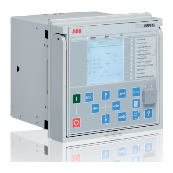
- Page 41 Section 2 1MAC050144-MB C 615 series overview Local HMI Figure 2: LHMI The LHMI of the IED contains the following elements: • Display • Buttons • LED indicators • Communication port The LHMI is used for setting, monitoring and controlling. 2.2.1 The LHMI includes a graphical LCD that supports one character sizes.
- Page 42 Section 2 1MAC050144-MB C 615 series overview Table 2: Characters and rows on the view Character size Rows in view Characters on row Large, variable width (13x14 10 rows min 8 pixels) 8 rows with large screen The display view is divided into four basic areas. Figure 3: Display layout Header...
- Page 43 Section 2 1MAC050144-MB C 615 series overview Figure 4: LHMI keypad with object control, navigation and command push-buttons and RJ-45 communication port Web HMI The WHMI enables the user to access the IED via a web browser. The supported web browser version is Internet Explorer 7.0 or Internet Explorer 8.0..
- Page 44 Section 2 1MAC050144-MB C 615 series overview Figure 5: Example view of the WHMI The WHMI can be accessed locally and remotely. • Locally by connecting your laptop to the IED via the front communication port. • Remotely over LAN/WAN. Authorization The user categories have been predefined for the LHMI and the WHMI, each with different rights and default passwords.
- Page 45 Section 2 1MAC050144-MB C 615 series overview Table 3: Predefined user categories Username User rights VIEWER Read only access OPERATOR • Selecting remote or local state with (only locally) • Changing setting groups • Controlling • Clearing alarm and indication LEDs and textual indications ENGINEER •...
- Page 46 Section 3 1MAC050144-MB C Basic functions Section 3 Basic functions General parameters Table 4: Analog input settings, phase currents Parameter Values (Range) Unit Step Default Description Secondary current 2=1A 2=1A Rated secondary current 3=5A Primary current 1.0...6000.0 600A Rated primary current Amplitude corr.
- Page 47 Section 3 1MAC050144-MB C Basic functions Table 6: Analog input settings, phase voltages Parameter Values (Range) Unit Step Default Description Primary voltage 0.001...440.000 0.001 20.000 Primary rated voltage Secondary voltage 60...210 Secondary rated voltage VT connection 1=Wye 2=Delta Wye, delta, U12 orUL1 VT connection 2=Delta 3=U12 4=UL1...
- Page 48 Section 3 1MAC050144-MB C Basic functions Table 9: Programmable LED settings Parameter Values (Range) Unit Step Default Description Alarm mode 0=Follow-S Alarm mode for programmable LED 1 0=Follow-S 1=Follow-F 2=Latched-S 3=LatchedAck-F-S Description Programmable LED 1 Programmable LED description Alarm mode 0=Follow-S 0=Follow-S Alarm mode for programmable LED 2...
- Page 49 Section 3 1MAC050144-MB C Basic functions Parameter Values (Range) Unit Step Default Description Alarm mode 0=Follow-S 0=Follow-S Alarm mode for programmable LED 11 1=Follow-F 2=Latched-S 3=LatchedAck-F-S Description Programmable LED 11 Programmable LED description 1)Non-latched mode 2)Non-latched blinking mode 3)Latched mode 4)Latched blinking mode Table 10: Authorization setting...
- Page 50 Section 3 1MAC050144-MB C Basic functions Table 13: Ethernet rear port: settings Parameter Values (Range) Unit Step Default Description IP address 192.168.2.10 IP address for rear port(s) Subnet mask 255.255.255.0 Subnet mask for rear port(s) Default gateway 192.168.2.1 Default gateway for rear port(s) Mac address XX-XX-XX-XX-XX-XX Mac address for rear port(s)
- Page 51 Section 3 1MAC050144-MB C Basic functions Table 15: Non group settings Parameter Values (Range) Unit Step Default Description Date Date Time Time Time format 1=24H:MM:SS:MS 1=24H:MM:SS:MS Time format 2=12H:MM:SS:MS Date format 1=DD.MM.YYYY 1=DD.MM.YYYY Date format 2=DD/MM/YYYY 3=DD-MM-YYYY 4=MM.DD.YYYY 5=MM/DD/YYYY 6=YYYY-MM-DD 7=YYYY-DD-MM 8=YYYY/DD/MM‘...
- Page 52 Section 3 1MAC050144-MB C Basic functions Table 17: IEC 60870-5-103 settings Parameter Values (Range) Unit Step Default Description Serial port 1 0=Not in use 0=Not in use COM port for instance 1 1=COM 1 2=COM2 Address 1 1...255 Unit address for instance 1 Start delay 1 0...20 char...
- Page 53 Section 3 1MAC050144-MB C Basic functions Parameter Values (Range) Unit Step Default Description Class1OvInfNo 1 0...255 Information Number for Class 1 overflow indication for instance 1 Class1OvBackOff 1 0...500 Backoff Range for Class1 buffer for instance 1 GI Optimize 1 0=Standard 0=Standard Optimize GI traffic for instance 1...
- Page 54 Section 3 1MAC050144-MB C Basic functions Parameter Values (Range) Unit Step Default Description Frame4InUse 2 -1=Not in use -1=Not in use Active Class2 Frame 4 for instance 2 0=User frame 1=Standard frame 1 2=Standard frame 2 3=Standard frame 3 4=Standard frame 4 5=Standard frame 5 6=Private frame 6 7=Private frame 7...
- Page 55 Section 3 1MAC050144-MB C Basic functions Table 19: Modbus settings Parameter Values (Range) Unit Step Default Description Serial port 1 0=Not in use 0=Not in use COM port for Serial interface 1 1=COM 1 2=COM 2 Parity 1 0=none 2=even Parity for Serial interface 1 1=odd 2=even...
- Page 56 Section 3 1MAC050144-MB C Basic functions Parameter Values (Range) Unit Step Default Description CtlStructPWd2 **** Password for Modbus control struct 2 CtlStructPWd3 **** Password for Modbus control struct 3 CtlStructPWd4 **** Password for Modbus control struct 4 CtlStructPWd5 **** Password for Modbus control struct 5 CtlStructPWd6 ****...
- Page 57 Section 3 1MAC050144-MB C Basic functions Table 21: COM1/COM2 serial communication settings Parameter Values (Range) Unit Step Default Description Fiber mode 0=No fiber 0=No fiber Fiber mode for COM1 2=Fiber optic Serial mode 1=RS485 2Wire 1=RS485 2Wire Serial mode for COM1 2=RS485 4Wire 3=RS232 no handshake 4=RS232 with handshake...
- Page 58 Section 3 1MAC050144-MB C Basic functions Table 22: Serial communication settings Parameter Values (Range) Unit Step Default Description Fiber mode 0=No fiber 0=No fiber Fiber mode for COM2 2=Fiber optic Serial mode 1=RS485 2Wire 1=RS485 2Wire Serial mode for COM2 2=RS485 4Wire 3=RS232 no handshake 4=RS232 with handshake...
- Page 59 Section 3 1MAC050144-MB C Basic functions Table 23: Time: Non group settings Parameter Values (Range) Unit Step Default Description Date Date Time Time Time format 1=HH:MM:SS:MSAM 1=HH:MM:SS:MSAM Time format 2=HH:MM:SS:MSPM Date format 1=DD.MM.YYYY 5=MM/DD/YYYY Date format 2=DD/MM/YYYY 3=YYYY-MM-DD 4=MM.DD.YYYY 5=MM/DD/YYYY 6=YYYY-MM-DD 7=YYYY-DD-MM 8=YYYY/DD/MM...
- Page 60 Section 3 1MAC050144-MB C Basic functions Table 24: X100 PSM binary output signals Name Type Default Description X100-PO1 BOOLEAN 0=False Connectors 6-7 X100-PO2 BOOLEAN 0=False Connectors 8-9 X100-SO1 BOOLEAN 0=False Connectors 10c-11nc-12no X100-SO2 BOOLEAN 0=False Connectors 13c-14no X100-PO3 BOOLEAN 0=False Connectors 15-17/18-19 X100-PO4 BOOLEAN...
- Page 61 Section 3 1MAC050144-MB C Basic functions Table 27: X110 BIO binary input settings Parameter Values (Range) Unit Step Default Description Input 1 filter time 5...1000 Connectors 1-2 Input 2 filter time 5...1000 Connectors 3-4 Input 3 filter time 5...1000 Connectors 5-6c Input 4 filter time 5...1000 Connectors 7-6c...
- Page 62 Section 3 1MAC050144-MB C Basic functions Table 30: X130 BIO binary output signals Name Type Default Description X130-SO1 BOOLEAN 0=False Connectors 10c-11no-12nc X130-SO2 BOOLEAN 0=False Connectors 13c-14no-15nc X130-SO3 BOOLEAN 0=False Connectors 16c-17no-18nc Table 31: X130 BIO binary input signals Name Type Description X130-Input 1...
- Page 63 Section 3 1MAC050144-MB C Basic functions Table 34: X130 AIM binary input settings Parameter Values (Range) Unit Step Default Description Input 1 filter time 5...1000 Connectors 1-2 Input 2 filter time 5...1000 Connectors 3-4 Input 3 filter time 5...1000 Connectors 5-6 Input 4 filter time 5...1000 Connectors 7-8...
- Page 64 Figure 6: Output contact The internal fault code indicates the type of internal IED fault. When a fault appears, record the code so that it can be reported to ABB customer service. Table 35: Internal fault indications and codes Fault indication...
- Page 65 LHMI. The fault indication message can be manually cleared. If a fault appears, record the name and code so that it can be provided to ABB customer service.
- Page 66 Section 3 1MAC050144-MB C Basic functions Table 36: Warning indications and codes Warning indication Warning code Additional information Warning A watchdog reset has occurred. Watchdog reset Warning The auxiliary supply voltage has dropped too Power down det. low. Warning Error when building the IEC 61850 data model. IEC61850 error Warning Error in the Modbus communication.
- Page 67 Section 3 1MAC050144-MB C Basic functions LED indication control The IED includes a global conditioning function LEDPTRC that is used with the protection indication LEDs. LED indication control should never be used for tripping purposes. There is a separate trip logic function TRPPTRC available in the IED configuration.
- Page 68 IRIG-B sync source is selected and the IRIG-B signal source is connected. ABB has tested the IRIG-B with the following clock masters: • Tekron TTM01 GPS clock with IRIG-B output •...
- Page 69 Section 3 1MAC050144-MB C Basic functions The default value of all inputs is FALSE, which makes it possible to use only the required number of inputs and leave the rest disconnected. The setting group selection is not dependent on the SG_x_ACT outputs. Table 37: Optional operation modes for setting group selection SG operation mode...
- Page 70 Section 3 1MAC050144-MB C Basic functions Fault records The fault recording period begins from the pickup event of any protection function and ends if any protection function trips or the pickup(s) is restored before the trip event. If a pick-up is restored without an trip event, the pick-up duration shows the protection function that has picked-up first.
- Page 71 Section 3 1MAC050144-MB C Basic functions Table 40: FR Non group settings Parameter Values (Range) Unit Step Default Description Operation 1=Enable 1=Enable Operation Off / On 5=Disable Trig mode 0=Trip or Pickup 0=Trip or Pickup Triggering mode 1=Trip only 2=Pickup only Measurement mode 1=RMS 2=DFT...
- Page 72 Section 3 1MAC050144-MB C Basic functions Name Type Values (Range) Unit Description 50=DEFLPDEF1 51=DEFLPDEF2 53=DEFHPDEF1 56=EFPADM1 57=EFPADM2 58=EFPADM3 59=FRPFRQ1 60=FRPFRQ2 61=FRPFRQ3 62=FRPFRQ4 63=FRPFRQ5 64=FRPFRQ6 65=LSHDPFRQ1 66=LSHDPFRQ2 67=LSHDPFRQ3 68=LSHDPFRQ4 69=LSHDPFRQ5 71=DPHLPDOC1 72=DPHLPDOC2 74=DPHHPDOC1 77=MAPGAPC1 78=MAPGAPC2 79=MAPGAPC3 85=MNSPTOC1 86=MNSPTOC2 88=LOFLPTUC1 90=TR2PTDF1 91=LNPLDF1 92=LREFPNDF1 94=MPDIF1 96=HREFPDIF1...
- Page 73 Section 3 1MAC050144-MB C Basic functions Name Type Values (Range) Unit Description 112=NSPTOV1 113=NSPTOV2 116=PSPTUV1 118=ARCSARC1 119=ARCSARC2 120=ARCSARC3 -96=SPHIPTOC1 -93=SPHLPTOC2 -92=SPHLPTOC1 -89=SPHHPTOC2 -88=SPHHPTOC1 -86=SPHPTUV3 -85=SPHPTUV2 -84=SPHPTUV1 -82=SPHPTOV3 -81=SPHPTOV2 -80=SPHPTOV1 -25=OEPVPH4 -24=OEPVPH3 -23=OEPVPH2 -22=OEPVPH1 -19=PSPTOV2 -18=PSPTOV1 -15=PREVPTOC1 -12=PHPTUC2 -11=PHPTUC1 -9=PHIZ1 5=PHLTPTOC1 20=EFLPTOC4 26=EFHPTOC5 27=EFHPTOC6...
- Page 74 Section 3 1MAC050144-MB C Basic functions Name Type Values (Range) Unit Description Pickup duration FLOAT32 0.00...100.00 Maximum start duration of all stages during the fault Trip time FLOAT32 0.000...999999.999 Operate time Fault distance FLOAT32 0.00...9999.99 Distance to fault measured in pu Fault resistance FLOAT32 0.00...999.99...
- Page 75 Section 3 1MAC050144-MB C Basic functions Name Type Values (Range) Unit Description Current IC2 FLOAT32 0.000...50.000 Maximum phase C current (b) Current IG2 FLOAT32 0.000...50.000 Residual current (b) Current I0B FLOAT32 0.000...50.000 Calculated residual current (b) Current I1B FLOAT32 0.000...50.000 Positive sequence current (b) Current I2B FLOAT32...
- Page 76 Section 3 1MAC050144-MB C Basic functions Name Type Values (Range) Unit Description Frequency FLOAT32 -10.00...10.00 Hz/s Frequency gradient gradient Conductance Yo FLOAT32 -1000.00...1000.00 Conductance Yo Susceptance Yo FLOAT32 -1000.00...1000.00 Susceptance Yo Angle VG - IG FLOAT32 -180.00...180.00 Angle residual voltage - residual current Angle VBC - IA FLOAT32...
- Page 77 Section 3 1MAC050144-MB C Basic functions Figure 8: Binary input filtering Input signal Filtered input signal Filter time At the beginning, the input signal is at the high state, the short low state is filtered and no input state change is detected. The low state starting from the time t exceeds the filter time, which means that the change in the input state is detected and the time tag attached to the input change is t...
- Page 78 Section 3 1MAC050144-MB C Basic functions 3.8.3 Oscillation suppression Oscillation suppression is used to reduce the load from the system when a binary input starts oscillating. A binary input is regarded as oscillating if the number of valid state changes (= number of events after filtering) during one second is equal to or greater than the set oscillation level value.
- Page 79 Section 3 1MAC050144-MB C Basic functions 3.10.2 Operation principle All the inputs of the module are independent RTD and mA channels with individual protection, reference and optical isolation for each input, making them galvanically isolated from each other and from the rest of the module. However, the RTD inputs share a common ground.
- Page 80 Section 3 1MAC050144-MB C Basic functions setting to “Ohm”. When Value unit is set to “Ohm”, the linear scaling is not possible, but the default range (0…2000 Ω) can be set smaller with the Value maximum and Value minimum settings. 3.10.5 Input linear scaling Each RTD/mA input can be scaled linearly by the construction of a linear output function...
- Page 81 Section 3 1MAC050144-MB C Basic functions Table 46: Function identification, limits for the RTD/mA inputs Input Limit value RTD temperature, high > 200 °C RTD temperature, low < -40 °C mA current, high > 23 mA Resistance, high > 2000 Ω 3.10.7 Selfsupervision Each input sample is validated before it is fed into the filter algorithm.
- Page 82 Section 3 1MAC050144-MB C Basic functions Out of Range Value maximum AI_RANGE#=3 Val high high limit Hysteresis AI_RANGE#=1 Val high limit AI_RANGE#=0 AI_RANGE#=0 Val low limit AI_RANGE#=2 Val low low limit AI_RANGE#=4 Value Reported Value minimum Figure 10: Limit value supervision for RTD (130) The range information of “High-high limit”...
- Page 83 Section 3 1MAC050144-MB C Basic functions Figure 11: Integral deadband supervision The deadband value used in the integral calculation is configured with the Value deadband setting. The value represents the percentage of the difference between the maximum and minimum limits in the units of 0.001 percent * seconds. The reporting delay of the integral algorithms in seconds is calculated with the formula: ...
- Page 84 Section 3 1MAC050144-MB C Basic functions Since the function can be utilized in various measurement modes, thedefault values are set to the extremes; thus, it is very important to setcorrect limit values to suit the application before the deadbandsupervision works properly. 3.10.11 RTD temperature vs.
- Page 85 Section 3 1MAC050144-MB C Basic functions 3.10.12 RTD/mA input connection RTD inputs can be used with 2-wire or 3-wire connection with common ground. Whenusing the 3-wire connection, it is important that all three wires connecting the sensorare symmetrical, that is, the wires are of same type and length. The graphicalrepresentation of the RTD and milli-ampere input connections can be found under thesection "RTD/mA card variants".
- Page 86 Section 3 1MAC050144-MB C Basic functions Figure 13: Three RTD and resistance sensors connected according to the two wire connection for 6RTD/2mA card Figure 14: mA wiring connection for 6RTD/2mA card 615 series ANSI Technical Manual...
- Page 87 Section 3 1MAC050144-MB C Basic functions 3.10.13.2 2RTD/1mA card This type of card accepts 1 milli ampere input, 2 inputs from RTD sensors and 5 inputs from VTs. The Input 1 is assigned for current measurements, inputs 2 and 3 are for RTD sensors and inputs 4 to 8 are used for measuring input data from VT.
- Page 88 Section 3 1MAC050144-MB C Basic functions Figure 16: Three RTD and resistance sensors connected according to the two-wire connection for 2RTD/1mA card Figure 17: mA wiring connection for 2RTD/1mA card 615 series ANSI Technical Manual...
- Page 89 Section 3 1MAC050144-MB C Basic functions 3.10.14 Signals Table 50: X130 (RTD/mA) analog input signals Name Type Description ALARM BOOLEAN General alarm WARNING BOOLEAN General warning AI_VAL1 FLOAT32 mA input, Connectors 1-2, instantaneous value AI_VAL2 FLOAT32 mA input, Connectors 3-4, instantaneous value AI_VAL3 FLOAT32 RTD input, Connectors 5-6-11c, instantaneous value...
- Page 90 Section 3 1MAC050144-MB C Basic functions Table 52: mA input settings Parameter Values (Range) Unit Step Default Description Input mode 1=Not in use 1=Not in use Analogue input mode 5=0..20mA Input maximum 0...20 Maximum analogue input value for mA or resistance scaling Input minimum 0...20...
- Page 91 Section 3 1MAC050144-MB C Basic functions Name Type Values (Range) Unit Description AI_RANGE3 Enum 0=normal RTD input, Connectors 1=high 5-6-11c, range 2=low 3=high-high 4=low-low AI_DB4 FLOAT32 -10000.0...10000 RTD input, Connectors 7-8-11c, reported value AI_RANGE4 Enum 0=normal RTD input, Connectors 1=high 7-8-11c, range 2=low 3=high-high...
- Page 92 Section 3 1MAC050144-MB C Basic functions configured) indicate good process data. Invalid status is caused either by bad data quality bits or GOOSE communication failure. See IEC 61850 engineering guide for details. The OUT output passes the received GOOSE value for the application. Default value (0) is used if VALID output indicates invalid status.
- Page 93 Section 3 1MAC050144-MB C Basic functions 3.11.2.2 Functionality The GOOSERCV_DP function is used to connect the GOOSE double binary inputs to the application. 3.11.2.3 Signals Table 56: GOOSERCV_DP Input signals Name Type Default Description Dbpos Input signal Table 57: GOOSERCV_DP Output signals Name Type Description...
- Page 94 Section 3 1MAC050144-MB C Basic functions 3.11.4 GOOSERCV_INT8 function block 3.11.4.1 Function block Figure 21: Function block 3.11.4.2 Functionality The GOOSERCV_INT8 function is used to connect the GOOSE 8 bit integer inputs to the application. 3.11.4.3 Signals Table 60: GOOSERCV_INT8 Input signals Name Type Description...
- Page 95 Section 3 1MAC050144-MB C Basic functions The CL output signal indicates that the position is closed. Default value (0) is used if VALID output indicates invalid status. The OK output signal indicates that the position is neither in faulty or intermediate state. The default value (0) is used if VALID output indicates invalid status.
- Page 96 Section 3 1MAC050144-MB C Basic functions Table 65: GOOSERCV_CMV Output signals Name Type Description FLOAT32 Output signal (amplitude) FLOAT32 Output signal (angle) VALID BOOLEAN Output signal 3.11.7 GOOSERCV_ENUM function block 3.11.7.1 Function block GOOSERCV_ENUM VALID Figure 24: Function block 3.11.7.2 Functionality The GOOSERCV_ENUM function block is used to connect GOOSE enumerator inputs to the application.
- Page 97 Section 3 1MAC050144-MB C Basic functions 3.11.8.2 Functionality The GOOSERCV_INT32 function block is used to connect GOOSE 32 bit integer inputs to the application. 3.11.8.3 Signals Table 68: GOOSERCV_INT32 Input signals Name Type Default Description INT32 Input signal Table 69: GOOSERCV_INT32 Output signals Name Type...
- Page 98 Section 3 1MAC050144-MB C Basic functions The IN input can be connected to any logic application signal (logic function output, binary input, application function output or received GOOSE signal). Due to application logic quality bit propagation, each (simple and even combined) signal has quality which can be evaluated.
- Page 99 Section 3 1MAC050144-MB C Basic functions 3.12.4 T_F32_INT8 function block 3.12.4.1 Functionality T_F32_INT8 is a type conversion function. The function converts 32-bit floating type values to 8-bit integer type. The rounding operation is included. Output value saturates if the input value is below the minimum or above the maximum value.
- Page 100 Section 3 1MAC050144-MB C Basic functions Function block Figure 27: Function blocks Settings The function does not have any parameters available in LHMI or Protection and Control IED Manager (PCM600). 3.13.1.2 AND function block Functionality AND and AND6 are used to form general combinatory expressions with Boolean variables.
- Page 101 Section 3 1MAC050144-MB C Basic functions Settings The function does not have any parameters available in LHMI or Protection and Control IED Manager (PCM600). 3.13.1.3 XOR function block Functionality The exclusive OR function XOR is used to generate combinatory expressions with Boolean variables.
- Page 102 Section 3 1MAC050144-MB C Basic functions 3.13.1.5 MAX3 function block Functionality The maximum function MAX3 selects the maximum value from three analog values. The disconnected inputs have the value 0. Function block MAX3 Figure 31: Function block Settings The function does not have any parameters available in LHMI or Protection and Control IED Manager (PCM600).
- Page 103 Section 3 1MAC050144-MB C Basic functions R_Trig detects the transition from FALSE to TRUE at the CLK input. When the rising edge is detected, the element assigns the output to TRUE. At the next execution round, the output is returned to FALSE despite the state of the input. Function block R_TRIG Figure 33:...
- Page 104 Section 3 1MAC050144-MB C Basic functions T_POS_CL and T_POS_OP are used for extracting the circuit breaker status information. Respectively, T_POS_OK is used to validate the intermediate or faulty breaker position. Table 76: Cross reference between circuit breaker position and the output of the function block Output of the function block Circuit breaker position T_POS_CL...
- Page 105 Section 3 1MAC050144-MB C Basic functions active longer than the set Cold load time, also the output remains active until the input is deactivated Settings Table 77: PT Non group settings Parameter Values (Range) Unit Step Default Description Pulse delay time 1 0...3600000 Pulse delay time Pulse delay time 2...
- Page 106 Section 3 1MAC050144-MB C Basic functions 3.13.2.2 Minimum second pulse timer 62CLD-1 Identification IEC 61850 IEC 60617 ANSI/IEEE C37.2 Functional description identification identification device number Minimum second pulse timer TPSGAPC TPS (1) 62CLD-1 Function block 62CLD1 OUT1 OUT2 Figure 38: Function block Functionality The Minimum minute pulse timer function 62CLD-2 contains two independent timers.
- Page 107 Section 3 1MAC050144-MB C Basic functions 3.13.2.3 Minimum minute pulse timer 62CLD-2 Identification IEC 61850 IEC 60617 ANSI/IEEE C37.2 Functional description identification identification device number Minimum minute pulse timer TPMGAPC TPM (1) 62CLD-2 Function block 62CLD2 OUT1 OUT2 Figure 40: Function block Functionality The Minimum minute pulse timer function 62CLD-2 contains two independent timers.
- Page 108 Section 3 1MAC050144-MB C Basic functions Figure 41: A = Trip pulse is shorter than Cold load time setting, B = Trip pulse is longer than Cold load time setting 3.13.3 Local/remote control function block CONTROL 3.13.3.1 Function block CONTROL CTRL_OFF CTRL_LOC LOCAL...
- Page 109 Section 3 1MAC050144-MB C Basic functions Table 78: Truth table for CONTROL Input Output CTRL_RE CTRL_STA CTRL_OFF CTRL_LOC TRUE OFF = TRUE FALSE TRUE LOCAL = TRUE FALSE FALSE TRUE STATION = TRUE FALSE FALSE FALSE TRUE REMOTE = TRUE FALSE FALSE FALSE...
- Page 110 Section 3 1MAC050144-MB C Basic functions 3.13.3.5 Monitored data Table 82: CONTROL Monitored data Parameter Type Values (Range) Unit Description Command ENUM 1 = "Select open" Latest command response response 2 = "Select close" 3 = "Operate open" 4 = "Operate close" 5 = "Direct open"...
- Page 111 Section 3 1MAC050144-MB C Basic functions parameter and the amount of quantities selected. The record output is in the COMTRADE format. 3.15.1.1 Quantities Selectable quantities are product-dependent. Table 83: Quantity Quantity Description Disabled Quantity not selected Phase A Current Primary Side Phase B Current Primary Side Phase C Current Primary Side Neutral/ground/residual current Primary Side...
- Page 112 Section 3 1MAC050144-MB C Basic functions Quantity Description Real power, Phase B Real power, Phase C Reactive power, Phase A Reactive power, Phase B Reactive power, Phase C Power Factor, Phase A Power Factor, Phase B Power Factor, Phase C Apparent power, Phase A Secondary Side Apparent power, Phase B Secondary Side Apparent power, Phase C Secondary Side...
- Page 113 Section 3 1MAC050144-MB C Basic functions Table 84: Recording capability in days with different settings Demand interval minute minutes minutes minutes minutes minutes minutes Recording capability in days Amount quantities 15.2 75.8 151.6 227.4 454.9 909.7 2729.2 11.4 56.9 113.7 170.6 341.1 682.3...
- Page 114 Section 3 1MAC050144-MB C Basic functions GUID-43078009-323D-409C-B84A-5EB914CDEE53 V1 EN Figure 43: Load profile record file naming 3.15.1.4 Clearing of record The load profile record can be cleared with Reset load profile rec via HMI, communication or the ACT input in PCM600. Clearing of the record is allowed only on the engineer and administrator authorization levels.
- Page 115 Section 3 1MAC050144-MB C Basic functions The IP number of the IED and the content of the Bay name setting are both included in the COMTRADE configuration file for identification purposes. 3.15.3 Signals. Table 85: LoadProf Output signals Name Type Description Rec.
- Page 116 Section 4 1MAC050144-MB C Protection functions Section 4 Protection functions Current protection 4.1.1 Three-phase non-directional overcurrent protection 51P/50P 4.1.1.1 Identification IEC 61850 IEC 60617 ANSI/IEEE C37.2 Function description identification identification device number Three-phase non-directional overcurrent PHLPTOC 3I> protection - Low stage Three-phase non-directional overcurrent PHHPTOC 3I>>...
- Page 117 Section 4 1MAC050144-MB C Protection functions The operation of three-phase non-directional overcurrent protection can be described by using a module diagram. All the blocks in the diagram are explained in the next sections. Figure 45: Functional module diagram. I_A, I_B and I_C represent phase currents. Level detector The measured phase currents are compared phase-wise with the set Pickup value.
- Page 118 Section 4 1MAC050144-MB C Protection functions Figure 46: Pickup value behavior with input activated ENA_MULT Phase selection logic If the fault criteria are fulfilled in the level detector, the phase selection logic detects the phase or phases in which the measured current exceeds the setting. If the phase information matches the Num of pickup phases setting, the phase selection logic activates the timer module.
- Page 119 Section 4 1MAC050144-MB C Protection functions The "Inverse reset" selection is only supported with ANSI or user programmable types of the IDMT operating curves. If another operating curve type is selected, an immediate reset occurs during the drop-off situation. The setting Time multiplier is used for scaling the IDMT trip and reset times. The setting parameter Minimum trip time defines the minimum desired trip time for IDMT.
- Page 120 C37.112 and six with the IEC 60255-3 standard. Two curves follow the special characteristics of ABB praxis and are referred to as RI and RD. In addition to this, a user programmable curve can be used if none of the standard curves are applicable. The user can choose the DT characteristic by selecting the Operating curve type values "ANSI Def.
- Page 121 Section 4 1MAC050144-MB C Protection functions Table 89: Reset time characteristics supported by different stages Supported by Reset curve type 50P-1/2 Note (1) Immediate Available for all reset time curves (2) Def time reset Available for all reset time curves (3) Inverse reset Available only for ANSI and user programmable...
- Page 122 Section 4 1MAC050144-MB C Protection functions Transformer and busbar overcurrent protection with reverse blocking principle By implementing a full set of overcurrent protection stages and blocking channels between the protection stages of the incoming feeders, bus-tie and outgoing feeders, it is possible to speed up the operation of overcurrent protection in the busbar and transformer LV-side faults without impairing the selectivity.
- Page 123 Section 4 1MAC050144-MB C Protection functions Figure 47: Numerical overcurrent protection functionality for a typical sub-transmission/distribution substation (feeder protection not shown). Blocking output = digital output signal from the start of a protection stage, Blocking in = digital input signal to block the operation of a protection stage The operating times of the time selective stages are very short, because the grading margins between successive protection stages can be kept short.
- Page 124 Section 4 1MAC050144-MB C Protection functions Radial outgoing feeder overcurrent protection The basic requirements for feeder overcurrent protection are adequate sensitivity and operation speed taking into account the minimum and maximum fault current levels along the protected line, selectivity requirements, inrush currents and the thermal and mechanical withstand of the lines to be protected.
- Page 125 Section 4 1MAC050144-MB C Protection functions Figure 48: Functionality of numerical multiple-stage overcurrent protection The coordination plan is an effective tool to study the operation of time selective operation characteristics. All the points mentioned earlier, required to define the overcurrent protection parameters, can be expressed simultaneously in a coordination plan.
- Page 126 Section 4 1MAC050144-MB C Protection functions Figure 49: Example coordination of numerical multiple-stage overcurrent protection 4.1.1.8 Signals Table 91: 51P Input signals Name Type Default Description SIGNAL Phase A current SIGNAL Phase B current SIGNAL Phase C current BLOCK BOOLEAN 0=False Block signal for activating the blocking mode ENA_MULT...
- Page 127 Section 4 1MAC050144-MB C Protection functions Table 95: 50P-1/2 Output signals Name Type Description TRIP BOOLEAN Trip PICKUP BOOLEAN Pickup Table 96: 50P-3 Output signals Name Type Description TRIP BOOLEAN Trip PICKUP BOOLEAN Pickup 4.1.1.9 Settings Table 97: 51P Group settings Parameter Values (Range) Unit...
- Page 128 Section 4 1MAC050144-MB C Protection functions Table 98: 51P Non group settings Parameter Values (Range) Unit Step Default Description Operation 1=Enable 1=Enable Operation Disable / Enable 5=Disable Num of pickup phases 1=1 out of 3 1=1 out of 3 Number of phases required for trip activation 2=2 out of 3 3=3 out of 3 Minimum trip time...
- Page 129 Section 4 1MAC050144-MB C Protection functions Table 100: 50P-1/2 Non group settings Parameter Values (Range) Unit Step Default Description Operation 1=Enable 5=Disable Operation Disable / Enable 5=Disable Num of pickup phases 1=1 out of 3 1=1 out of 3 Number of phases required for trip activation 2=2 out of 3 3=3 out of 3 Minimum trip time...
- Page 130 Section 4 1MAC050144-MB C Protection functions Table 104: 50P-1/2 Monitored data Name Type Values (Range) Unit Description PICKUP_DUR FLOAT32 0.00...100.00 Ratio of pickup time / trip time 50P-1/2 Enum 1=enabled Status 2=blocked 3=test 4=test/blocked 5=disabled Table 105: 50P-3 Monitored data Name Type Values (Range)
- Page 131 Section 4 1MAC050144-MB C Protection functions 4.1.1.12 Technical revision history Table 107: 50P–3 Technical revision history Technical revision Change Minimum and default values changed to 20 ms for Trip delay time setting. Pickup Minimum value changed to 1.00 x I for the value setting.
- Page 132 Section 4 1MAC050144-MB C Protection functions 4.1.2.4 Operation principle The function can be enabled and disabled with the Operation setting. The corresponding parameter values are Enable and Disable. The operation of three-phase long-time overcurrent protection can be described by using a module diagram.
- Page 133 Section 4 1MAC050144-MB C Protection functions Figure 52: Pickup value behavior with ENA_MULT input activated Phase selection logic If the fault criteria are fulfilled in the level detector, the phase selection logic detects the phase or phases in which the measured current exceeds the setting. If the phase information matches the Num of pickup phases setting, the phase selection logic activates the timer module.
- Page 134 Section 4 1MAC050144-MB C Protection functions blocked and the timers are reset. In the "Block TRIP output" mode, the function operates normally but the TRIP output is not activated. 4.1.2.5 Timer characteristics 51LT supports both DT and IDMT characteristics. The user can select the timer characteristics with the Operating curve type and Type of reset curve settings.
- Page 135 Section 4 1MAC050144-MB C Protection functions 4.1.2.7 Signals Table 112: 51LT Input signals Name Type Default Description SIGNAL Phase A current SIGNAL Phase B current SIGNAL Phase C current BLOCK BOOLEAN 0=false Block signal for activating the blocking mode ENA_MULT BOOLEAN 0-false Enable signal for current multiplier...
- Page 136 Section 4 1MAC050144-MB C Protection functions Table 115: 51LT Non group settings Parameter Values (Range) Unit Step Default Description Operation 1=Enable 5=Disable Operation Disable / Enable 5=Disable Num of pickup phases 1=1 out of 3 1=1 out of 3 Number of phases required for trip activation 2=2 out of 3 3=3 out of 3 Minimum trip time...
- Page 137 Section 4 1MAC050144-MB C Protection functions 4.1.3.2 Function block 67/50P-2 67/51P 67/50P-1 TRIP TRIP TRIP PICKUP PICKUP PICKUP V_A_AB V_A_AB V_A_AB V_B_BC V_B_BC V_B_BC V_C_CA V_C_CA V_C_CA BLOCK BLOCK BLOCK ENA_MULT ENA_MULT ENA_MULT Figure 53: Function block 4.1.3.3 Functionality The three-phase overcurrent protection 67/51P and 67/50P is used as one-phase, two-phase or three-phase directional overcurrent and short-circuit protection for feeders.
- Page 138 Section 4 1MAC050144-MB C Protection functions Figure 54: Functional module diagram Directional calculation The directional calculation compares the current phasors to the polarizing phasor. The user can select the suitable one from different polarization quantities which are the positive sequence voltage, negative sequence voltage, self polarizing (faulted) voltage and cross polarizing voltages (healthy voltages).
- Page 139 Section 4 1MAC050144-MB C Protection functions Reliable operation requires both the operating and polarizing quantities to exceed certain minimum amplitude levels. The minimum amplitude level for the operating quantity (current) is set with the Min trip current setting. The minimum amplitude level for the polarizing quantity (voltage) is set with the Min trip voltage setting.
- Page 140 Section 4 1MAC050144-MB C Protection functions Figure 55: Operating zones at minimum magnitude levels Level detector The measured phase currents are compared phase-wise with the set Pickup value. If the measured value exceeds the set Pickup value, the level detector reports the exceeding of the value to the phase selection logic.
- Page 141 Section 4 1MAC050144-MB C Protection functions Figure 56: Pickup value behavior with input activated ENA_MULT Phase selection logic If the fault criteria are fulfilled in the level detector and the directional calculation, the phase selection logic detects the phase or phases in which the measured current exceeds the setting.
- Page 142 Section 4 1MAC050144-MB C Protection functions reset", the reset time depends on the Reset delay time setting. With the reset curve type "Inverse reset", the reset time depends on the current during the drop-off situation. If the drop-off situation continues, the reset timer is reset and the PICKUP output is deactivated. The "Inverse reset"...
- Page 143 Section 4 1MAC050144-MB C Protection functions Table 118: Measurement modes supported by 67/51P and 67/50P stages Supported measurement modes Measurement mode 67/51P and 67/50P-1 67/50P-2 Peak-to-Peak 4.1.3.6 Directional overcurrent characteristics The forward and reverse sectors are defined separately. The forward operation area is limited with the Min forward angle and Max forward angle settings.
- Page 144 Section 4 1MAC050144-MB C Protection functions Figure 57: Configurable operating sectors Table 119: Momentary per phase direction value for monitored data view Criterion for per phase direction information The value for DIR_A/_B/_C The ANGLE_X is not in any of the defined sectors, 0 = unknown or the direction cannot be defined due too low amplitude...
- Page 145 Section 4 1MAC050144-MB C Protection functions Self-polarizing as polarizing method Table 121: Equations for calculating angle difference for self-polarizing method Used Used Faulted fault polarizing Angle difference phases current voltage = ANGLE A = ANGLE B = ...
- Page 146 Section 4 1MAC050144-MB C Protection functions Figure 59: Two-phase short circuit, short circuit is between phases B and C Cross-polarizing as polarizing quantity Table 122: Equations for calculating angle difference for cross-polarizing method Used Used Faulted fault polarizing Angle difference phases current voltage...
- Page 147 Section 4 1MAC050144-MB C Protection functions Figure 60: Single-phase ground fault, phase A In an example of the phasors in a two-phase short-circuit failure where the fault is between the phases B and C, the angle difference is measured between the polarizing quantity V and operating quantity I marked as φ.
- Page 148 Section 4 1MAC050144-MB C Protection functions Figure 61: Two-phase short circuit, short circuit is between phases B and C The equations are valid when network rotating direction is counterclockwise, that is, ABC. If the network rotating direction is reversed, 180 degrees is added to the calculated angle difference. This is done automatically with a system parameter Phase rotation.
- Page 149 Section 4 1MAC050144-MB C Protection functions Figure 62: Phasors in a single-phase ground fault, phases A-N, and two-phase short circuit, phases B and C, when the actuating polarizing quantity is the negative-sequence voltage -V2 Positive-sequence voltage as polarizing quantity Table 123: Equations for calculating angle difference for positive-sequence quantity polarizing method Used Faulted...
- Page 150 Section 4 1MAC050144-MB C Protection functions Figure 63: Phasors in a single-phase ground fault, phase A to ground, and a two-phase short circuit, phases B-C, are short-circuited when the polarizing quantity is the positive-sequence voltage V1 Network rotating direction Typically, the network rotating direction is counterclockwise and defined as "ABC". If the network rotating direction is reversed, meaning clockwise, that is, "ACB", the equations for calculating the angle difference need to be changed.
- Page 151 Section 4 1MAC050144-MB C Protection functions Figure 64: Examples of network rotating direction 4.1.3.7 Application 67/51P and 67/50P is used as short-circuit protection in three-phase distribution or sub transmission networks operating at 50 or 60 Hz. In radial networks, phase overcurrent IEDs are often sufficient for the short circuit protection of lines, transformers and other equipment.
- Page 152 Section 4 1MAC050144-MB C Protection functions Figure 65: Overcurrent protection of parallel lines using directional IEDs 67/51P and 67/50P can be used for parallel operating transformer applications. In these applications, there is a possibility that the fault current can also be fed from the LV-side up to the HV-side.
- Page 153 Section 4 1MAC050144-MB C Protection functions Figure 67: Closed ring network topology where feeding lines are protected with directional overcurrent IEDs 4.1.3.8 Signals Table 124: 67/51P-1 and 67/50P-1 Input signals Name Type Default Description SIGNAL Phase A current SIGNAL Phase B current SIGNAL Phase C current SIGNAL...
- Page 154 Section 4 1MAC050144-MB C Protection functions Table 125: 67/50P-2 Input signals Name Type Default Description SIGNAL Phase A current SIGNAL Phase B current SIGNAL Phase C current SIGNAL Negative phase sequence current V_A_AB SIGNAL Phase to ground voltage A or phase to phase voltage AB V_B_BC SIGNAL Phase to ground voltage B or phase to phase voltage BC...
- Page 155 Section 4 1MAC050144-MB C Protection functions Parameter Values (Range) Unit Step Default Description Type of reset curve 1=Immediate 1=Immediate Selection of reset curve type 2=Def time reset 3=Inverse reset Voltage Mem time 0...3000 Voltage memory time Directional mode 1=Non-directional 2=Forward Directional mode 2=Forward 3=Reverse...
- Page 156 Section 4 1MAC050144-MB C Protection functions Table 130: 67/50P-2 Group settings Parameter Values (Range) Unit Step Default Description Pickup value 0.10...40.00 0.01 1.00 Pickup value Pickup value mult 0.8...10.0 Multiplier for scaling the pickup value Directional mode 1=Non-directional 2=Forward Directional mode 2=Forward 3=Reverse Time multiplier...
- Page 157 Section 4 1MAC050144-MB C Protection functions Table 131: 67/50P-2 Non group settings Parameter Values (Range) Unit Step Default Description Operation 1=Enable 5=Disable Operation Disable / Enable 5=Disable Reset delay time 0...60000 Reset delay time Minimum trip time 20...60000 Minimum trip time for IDMT curves Allow Non Dir 0=False 0=False...
- Page 158 Section 4 1MAC050144-MB C Protection functions 4.1.3.10 Monitored data Table 132: 67/51P-1 and 67/50P-1 Monitored data Name Type Values (Range) Unit Description PICKUP_DUR FLOAT32 0.00...100.00 Ratio of pickup time / trip time FAULT_DIR Enum 0=unknown Detected fault direction 1=forward 2=backward 3=both DIRECTION Enum...
- Page 159 Section 4 1MAC050144-MB C Protection functions Table 133: 67/50P-2 Monitored data Name Type Values (Range) Unit Description PICKUP_DUR FLOAT32 0.00...100.00 Ratio of pickup time / trip time FAULT_DIR Enum 0=unknown Detected fault direction 1=forward 2=backward 3=both DIRECTION Enum 0=unknown Direction information 1=forward 2=backward 3=both...
- Page 160 Section 4 1MAC050144-MB C Protection functions 4.1.3.11 Technical data Table 134: 67/51P and 67/50P Technical data Characteristic Value Pickup accuracy Depending on the frequency of the current/voltage measured: f ±2Hz 67/51P and 67/50P-1 Current: ±1.5% of the set value or ±0.002 x I Voltage: ±1.5% of the set value or ±0.002 x V Phase angle: ±2°...
- Page 161 Section 4 1MAC050144-MB C Protection functions 4.1.4.2 Function block Figure 68: Function block 4.1.4.3 Functionality The ground-fault function 51N/50N or 51G/50G is used as non-directional ground-fault protection for feeders. The function picks up and trips when the measured (IG) or calculated (IN) ground current exceeds the set limit.
- Page 162 Section 4 1MAC050144-MB C Protection functions Do not set the multiplier setting Pickup value Mult higher than necessary. If the value is too high, the function may not trip at all during an inrush followed by a fault, no matter how severe the fault is. The pickup value multiplication is normally done when the inrush detection function (INR) is connected to the ENA_MULT input.
- Page 163 C37.112 and six with the IEC 60255-3 standard. Two curves follow the special characteristics of ABB praxis and are referred to as RI and RD. In addition to this, a user programmable curve can be used if none of the standard curves are applicable. The user can choose the DT characteristic by selecting the Operating curve type values "ANSI Def.
- Page 164 Section 4 1MAC050144-MB C Protection functions Table 136: Timer characteristics supported by different stages Supported by Operating curve type 51N/G 50N/G-1/2 (1) ANSI Extremely Inverse (2) ANSI Very Inverse (3) ANSI Normal Inverse (4) ANSI Moderately Inverse (5) ANSI Definite Time (6) Long Time Extremely Inverse (7) Long Time Very Inverse...
- Page 165 Section 4 1MAC050144-MB C Protection functions 4.1.4.7 Application 51N/50N or 51G/50G is designed for protection and clearance of ground faults in distribution and sub-transmission networks where the neutral point is isolated or grounded via a resonance coil or through low resistance. It also applies to solidly grounded networks and ground-fault protection of different equipment connected to the power systems, such as shunt capacitor bank or shunt reactors and for backup ground-fault protection of power transformers.
- Page 166 Section 4 1MAC050144-MB C Protection functions Table 142: 50N/G-1/2 Output signals Name Type Description TRIP BOOLEAN Trip PICKUP BOOLEAN Pickup Table 143: 50N/G-3 Output signals Name Type Description TRIP BOOLEAN Trip PICKUP BOOLEAN Pickup 4.1.4.9 Settings Table 144: 51N/G and 50SEF Group settings Parameter Values (Range) Unit...
- Page 167 Section 4 1MAC050144-MB C Protection functions Table 145: 51N/G and 50SEF Non group settings Parameter Values (Range) Unit Step Default Description Operation 1=Enable 5=Disable Operation Disable / Enable 5=Disable Minimum trip time 20...60000 Minimum trip time for IDMT curves Reset delay time 0...60000 Reset delay time Measurement mode...
- Page 168 Section 4 1MAC050144-MB C Protection functions Table 148: 50N/G-3 Group settings Parameter Values (Range) Unit Step Default Description Pickup value 1.00...40.00 0.01 1.00 Pickup value Pickup value mult 0.8...10.0 Multiplier for scaling the pickup value Trip delay time 20...200000 Trip delay time Table 149: 50N/G-3 Non group settings Parameter...
- Page 169 Section 4 1MAC050144-MB C Protection functions 4.1.4.11 Technical data Table 153: 51N/G, 50N/G-1/2 & 50N/G-3 Technical data Pickup accuracy Depending on the frequency of the current measured: f ±2Hz 51N/G ±1.5% of the set value or ±0.002 x I 50N-1/2 & 50G-1/2 ±1.5% of set value or ±0.002 x I (at currents in the range of 0.1…10 x I 50N/G-3...
- Page 170 Section 4 1MAC050144-MB C Protection functions 4.1.5 Sensitive ground-fault protection 50SEF 4.1.5.1 Identification IEC 61850 IEC 60617 ANSI/IEEE C37.2 Function description identification identification device number Non-directional sensitive ground-fault EFLPTOC > 50SEF protection 4.1.5.2 Function block Figure 70: Function block 4.1.5.3 Functionality A small percentage of the ground faults have very large impedance.
- Page 171 Section 4 1MAC050144-MB C Protection functions 4.1.5.9 Settings Same as 51N as described in 4.1.4.9 above. 4.1.5.10 Monitored data Same as 51N as described in 4.1.4.10 above. 4.1.5.11 Technical data Same as 50N as described in 4.1.4.11 above. 4.1.6 Directional ground-fault protection 67/51N and 67/50N 4.1.6.1 Identification IEC 61850...
- Page 172 Section 4 1MAC050144-MB C Protection functions 4.1.6.4 Operation principle The function can be enabled and disabled with the Operation setting. The corresponding parameter values are Enable and Disable. The operation of directional ground-fault protection can be described by using a module diagram.
- Page 173 Section 4 1MAC050144-MB C Protection functions For defining the operation sector, there are five modes available through the Operation mode setting. Table 157: Operation modes Operation mode Description Phase angle The operating sectors for forward and reverse are Min forward angle defined with the settings forward angle Min reverse angle...
- Page 174 Section 4 1MAC050144-MB C Protection functions Table 158: Monitored data values Monitored data values Description FAULT_DIR The detected direction of fault during fault situations, that is, when START output is active. DIRECTION The momentary operating direction indication output. ANGLE Also called operating angle, shows the angle difference between the VG (polarizing quantity) and Io (operating quantity).
- Page 175 Section 4 1MAC050144-MB C Protection functions The setting parameter Minimum trip time defines the minimum desired trip time for IDMT. The setting is applicable only when the IDMT curves are used. The Minimum trip time setting should be used with great care because the operation time is according to the IDMT curve, but always at least the value of the Minimum operate time setting.
- Page 176 Section 4 1MAC050144-MB C Protection functions maximum torque line Characteristic angle = 0 deg -V (polarizing quantity) (operating quantity) Min forward angle Max forward angle Non-operating area zero torque line Max reverse angle Min reverse angle Min operate current Figure 73: Definition of the relay characteristic angle, RCA=0 degrees in a compensated network Example 2.
- Page 177 Section 4 1MAC050144-MB C Protection functions (polarizing quantity) Characteristic angle = +60 deg maximum torque line Min forward angle Min operate current (operating quantity) Max reverse angle Max forward angle Min reverse angle zero torque line Figure 74: Definition of the relay characteristic angle, RCA=+60 degrees in a solidly grounded network Example 3.
- Page 178 Section 4 1MAC050144-MB C Protection functions (polarizing quantity) Characteristic angle = -90 deg Max forward angle Min reverse angle maximum torque line (operating quantity) Min forward angle Max reverse angle Min operate current zero torque line Figure 75: Definition of the relay characteristic angle, RCA=–90 degrees in an isolated network Directional ground-fault protection in an isolated neutral network In isolated networks, there is no intentional connection between the system neutral point...
- Page 179 Section 4 1MAC050144-MB C Protection functions ΣI ΣI ΣI Figure 76: Ground-fault situation in an isolated network Directional ground-fault protection in a compensated network In compensated networks, the capacitive fault current and the inductive resonance coil current compensate each other. The protection cannot be based on the reactive current measurement, since the current of the compensation coil would disturb the operation of the relays.
- Page 180 Section 4 1MAC050144-MB C Protection functions ΣI ΣI ΣI ΣI Figure 77: Ground-fault situation in a compensated network The Petersen coil or the grounding resistor may be temporarily out of operation. To keep the protection scheme selective, it is necessary to update the characteristic angle setting accordingly.
- Page 181 Section 4 1MAC050144-MB C Protection functions coil or the grounding resistor. This is the case for instance, when a directional ground-fault relay is used in an MV-switching substation some kilometers from the HV/MV -substation in which the grounding facilities are located. Another example is when HV/MV-substations are connected in parallel but located far from each other.
- Page 182 C37.112 and six with the IEC 60255-3 standard. Two curves follow the special characteristics of ABB praxis and are referred to as RI and RD. In addition to this, a user programmable curve can be used if none of the standard curves are applicable. The user can choose the DT characteristic by selecting the Operating curve type values "ANSI Def.
- Page 183 Section 4 1MAC050144-MB C Protection functions Table 163: Reset time characteristics supported by different stages Supported by Reset curve type 67/51N and 67/50N-1 67/50N-2 Note (1) Immediate Available for all operate time curves (2) Def time reset Available for all operate time curves (3) Inverse reset Available only for ANSI...
- Page 184 Section 4 1MAC050144-MB C Protection functions = 0 deg Forward area Min forward angle Max forward angle Non-operating area Max reverse angle Min reverse angle Backward Min operate current area Figure 79: Configurable operating sectors in phase angle characteristic Table 164: Momentary operating direction Fault direction The value for DIRECTION...
- Page 185 Section 4 1MAC050144-MB C Protection functions The RCA_CTL input is used in compensated networks where the compensation coil sometimes can be disconnected. When the coil is disconnected, the compensated network becomes isolated and the Characteristic angle setting (φRCA) must be changed. This can be done automatically with the RCA_CTL input.
- Page 186 Section 4 1MAC050144-MB C Protection functions magnitude, the FAULT_DIR and DIRECTION outputs are set to 0 = unknown, except when the Allow non dir setting is "True". In that case, the function is allowed to operate in the directional mode as non-directional, since the directional information is invalid. The calculated I sin(φ) or I cos(φ) current used in direction determination can be read...
- Page 187 Section 4 1MAC050144-MB C Protection functions Example 2. sin(φ) criterion selected, reverse-type fault => FAULT_DIR = 2 Correction angle = -90 deg Min operating current Figure 81: Operating characteristic I sin(φ) in reverse fault Example 3. cos(φ) criterion selected, forward-type fault =>...
- Page 188 Section 4 1MAC050144-MB C Protection functions = 0 deg Correction angle Min operating current Figure 82: Operating characteristic I cos(φ) in forward fault Example 4. cos(φ) criterion selected, reverse-type fault => FAULT_DIR = 2 615 series ANSI Technical Manual...
- Page 189 Section 4 1MAC050144-MB C Protection functions = 0 deg Min operating current Correction angle Figure 83: Operating characteristic I cos(φ) in reverse fault Phase angle, classic 80 The operation criterion phase angle classic 80 is selected with the Operation mode setting using the value "Phase angle 80".
- Page 190 Section 4 1MAC050144-MB C Protection functions Forward area 70 deg 80 deg Min forward angle Non-operating area Max forward angle 80 deg 70 deg Max reverse angle Min reverse angle Backward 3% nominal amplitude area 1% nominal amplitude Figure 84: Operating characteristic for phase angle classic 80 / % of Min forward angle...
- Page 191 Section 4 1MAC050144-MB C Protection functions • The Max forward angle and Max reverse angle settings are not settable, but have a fixed value of 88 degrees • The sector limits of the fixed sectors are rounded. Sector rounding in the phase angle classic 88 consists of three parts: •...
- Page 192 Section 4 1MAC050144-MB C Protection functions / % of 88 deg 100% Min forward angle Forward area 85 deg Non- 73 deg operating 1% of area Figure 87: Phase angle classic 88 amplitude 4.1.6.9 Application The directional ground-fault protection (67/51N and 67/50N) is designed for protection and clearance of ground faults and for ground-fault protection of different equipment connected to the power systems, such as shunt capacitor banks or shunt reactors, and for backup ground-fault protection of power transformers.
- Page 193 Section 4 1MAC050144-MB C Protection functions System neutral grounding is meant to protect personnel and equipment and to reduce interference for example in telecommunication systems. The neutral grounding sets challenges for protection systems, especially for ground-fault protection. In isolated networks, there is no intentional connection between the system neutral point and ground.
- Page 194 Section 4 1MAC050144-MB C Protection functions Figure 88: Connection of measuring transformers 4.1.6.10 Signals Table 167: 67/51N and 67/50N-1 Input signals Name Type Default Description I0 or IG or I2 SIGNAL Zero Sequence current / Negative sequence current V0 or VG or V2 SIGNAL Zero Sequence voltage / Negative sequence voltage BLOCK...
- Page 195 Section 4 1MAC050144-MB C Protection functions Table 170: 67/50N-2 Output signals Name Type Description TRIP BOOLEAN Trip PICKUP BOOLEAN Pickup 4.1.6.11 Settings Table 171: 67/51N and 67/50N-1 Group settings Parameter Values (Range) Unit Step Default Description Pickup value 0.010...5.000 0.005 0.010 Pickup value Pickup value mult...
- Page 196 Section 4 1MAC050144-MB C Protection functions Table 172: 67/51N and 67/50N-1 Non group settings Parameter Values (Range) Unit Step Default Description Operation 1=Enable 5=Disable Operation Disable / Enable 5=Disable Reset delay time 0...60000 Reset delay time Minimum trip time 60...60000 Minimum trip time for IDMT curves Allow Non Dir 0=False...
- Page 197 Section 4 1MAC050144-MB C Protection functions Table 173: 67/50N-2 Group settings Parameter Values (Range) Unit Step Default Description Pickup value 0.10...40.00 0.01 0.10 Pickup value Pickup value mult 0.8...10.0 Multiplier for scaling the pickup value Directional mode 1=Non-directional 2=Forward Directional mode 2=Forward 3=Reverse Time multiplier...
- Page 198 Section 4 1MAC050144-MB C Protection functions Table 174: 67/50N-2 Non group settings Parameter Values (Range) Unit Step Default Description Operation 1=Enable 5=Disable Operation Disable / Enable 5=Disable Reset delay time 0...60000 Reset delay time Minimum trip time 40...60000 Minimum trip time for IDMT curves Allow Non Dir 0=False 0=False...
- Page 199 Section 4 1MAC050144-MB C Protection functions 4.1.6.12 Monitored data Table 175: 67/51N and 67/50N-1 Monitored data Values Name Type Unit Description (Range) FAULT_DIR Enum 0=unknown Detected fault direction 1=forward 2=backward 3=both PICKUP_DUR FLOAT 0.00...100.00 Ratio of pickup time / trip time DIRECTION Enum 0=unknown...
- Page 200 Section 4 1MAC050144-MB C Protection functions 4.1.6.13 Technical data Table 177: 67/51N and 67/50N Technical data Characteristic Value Pickup accuracy Depending on the frequency of the current measured: f ±2Hz 67/51N and 67/50N-1 Current: ±1.5% of the set value or ±0.002 x I Voltage ±1.5% of the set value or ±0.002 x V Phase angle:...
- Page 201 Section 4 1MAC050144-MB C Protection functions 4.1.7 Negative-sequence overcurrent protection 46 4.1.7.1 Identification IEC 61850 IEC 60617 ANSI/IEEE C37.2 Function description identification identification device number Negative sequence current protection NSPTOC I2> 4.1.7.2 Function block Figure 89: Function block 4.1.7.3 Functionality The negative sequence current protection 46 is used for increasing sensitivity to detect single phasing situations, unbalanced loads due to, for example, unsymmetrical feeder voltages.
- Page 202 Section 4 1MAC050144-MB C Protection functions Figure 90: Functional module diagram. I represents negative phase sequence current. Level detector The measured negative phase-sequence current is compared with the set Pickup value. If the measured value exceeds the set Pickup value, the level detector activates the timer module.
- Page 203 Section 4 1MAC050144-MB C Protection functions The "Inverse reset" selection is only supported with ANSI or user programmable types of the IDMT operating curves. If another operating curve type is selected, an immediate reset occurs during the drop-off situation. The setting Time multiplier is used for scaling the IDMT trip and reset times. The setting parameter Minimum trip time defines the minimum desired trip time for IDMT.
- Page 204 Section 4 1MAC050144-MB C Protection functions 4.1.7.6 Signals Table 180: 46 Input signals Name Type Default Description SIGNAL Negative phase sequence current BLOCK BOOLEAN 0=False Block signal for activating the blocking mode ENA_MULT BOOLEAN 0=False Enable signal for current multiplier Table 181: 46 Output signals Name...
- Page 205 Section 4 1MAC050144-MB C Protection functions Table 183: 46 Non group settings Parameter Values (Range) Unit Step Default Description Operation 1=Enable 5=Disable Operation Disable / Enable 5=Disable Minimum trip time 20...60000 Minimum trip time for IDMT curves Reset delay time 0...60000 Reset delay time Curve parameter A...
- Page 206 Section 4 1MAC050144-MB C Protection functions 4.1.7.10 Technical revision history Table 186: 46 Technical revision history Technical revision Change Minimum and default values changed to 40 ms for Trip delay time setting 4.1.8 Phase discontinuity protection 46PD 4.1.8.1 Identification IEC 61850 IEC 60617 ANSI/IEEE C37.2 Function description...
- Page 207 Section 4 1MAC050144-MB C Protection functions Figure 92: Functional module diagram. I and I represent positive and negative phase sequence currents. I_A, I_B and I_C represent phase currents. The I module calculates the ratio of the negative and positive phase sequence current. It reports the calculated value to the level detector.
- Page 208 Section 4 1MAC050144-MB C Protection functions input, a horizontal communication input or an internal signal of the relay program. The influence of the BLOCK signal activation is preselected with the global setting Blocking mode. The Blocking mode setting has three blocking methods. In the "Freeze timers" mode, the trip timer is frozen to the prevailing value.
- Page 209 Section 4 1MAC050144-MB C Protection functions Figure 93: Broken conductor fault in phase A in a distribution or subtransmission feeder Figure 94: Three-phase current quantities during the broken conductor fault in phase A with the ratio of negative and positive sequence currents 4.1.8.6 Signals Table 187:...
- Page 210 Section 4 1MAC050144-MB C Protection functions Table 188: 46PD Output signals Name Type Description TRIP BOOLEAN Trip PICKUP BOOLEAN Pickup 4.1.8.7 Settings Table 189: 46PD Group settings Parameter Values (Range) Unit Step Default Description Pickup value 10...100 Pickup value Trip delay time 100...30000 Trip delay time Table 190:...
- Page 211 Section 4 1MAC050144-MB C Protection functions 4.1.9 Negative-sequence overcurrent protection for motors, 46M 4.1.9.1 Identification IEC 61850 IEC 60617 ANSI/IEEE C37.2 Function description identification identification device number Negative sequence time overcurrent MNSPTOC I2>M protection 4.1.9.2 Function block Figure 95: Function block 4.1.9.3 Functionality The unbalance protection based on negative sequence current function 46M protects...
- Page 212 Section 4 1MAC050144-MB C Protection functions Timer TRIP Level detector PICKUP BLOCK BLK_RESTART Figure 96: Functional module diagram Level detector The calculated negative-sequence current is compared to the Pickup value setting. If the measured value exceeds the Pickup value setting, the function activates the timer module. Timer Once activated, the timer activates the PICKUP output.
- Page 213 Section 4 1MAC050144-MB C Protection functions The timer calculates the pickup duration value PICKUP_DUR which indicates the percentage ratio of the pickup situation and the set trip time. The value is available through the Monitored data view. 4.1.9.5 Timer characteristics 46M supports both DT and IDMT characteristics.
- Page 214 Section 4 1MAC050144-MB C Protection functions ⎛ ⎞ = × ⎜ ⎟ ⎝ ⎠ t[s] Reset time in seconds set Cooling time percentage of pickup time elapse (PICKUP_DUR) When the reset period is initiated, the time for which PICKUP has been active is saved. Now, if the fault reoccurs, that is, the negative-sequence current rises above the set value during the reset period, the trip calculations are continued using the saved values.
- Page 215 Section 4 1MAC050144-MB C Protection functions When the voltages supplied to an operating motor become unbalanced, the positive-sequence current remains substantially unchanged, but the negative-sequence current flows due to the unbalance. For example, if the unbalance is caused by an open circuit in any phase, a negative-sequence current flows and it is equal and opposite to the previous load current in a healthy phase.
- Page 216 Section 4 1MAC050144-MB C Protection functions Table 196: 46M Non group settings Parameter Values (Range) Unit Step Default Description Operation 1=Enable 5=Disable Operation Disable / Enable 5=Disable Rated current 0.30...2.00 0.01 1.00 Rated current (Ir) of the machine (used only in the IDMT) Maximum trip time 500000...7200000 1000...
- Page 217 Section 4 1MAC050144-MB C Protection functions 4.1.9.10 Technical data Table 198: 46M Technical data Pickup accuracy Depending on the frequency of the current measured: f ±2Hz ±1.5% of the set value or ±0.002 x I Minimum Typical Maximum Pickup time Pickup value = 2.0 x set 22 ms...
- Page 218 Section 4 1MAC050144-MB C Protection functions 4.1.10.4 Operation principle The function can be enabled and disabled with the Operation setting. The corresponding parameter values are Enable and Disable. The operation of phase-reversal protection can be described by using a module diagram. All the modules in the diagram are explained in the next sections.
- Page 219 Section 4 1MAC050144-MB C Protection functions 4.1.10.6 Signals Table 199: 46R Input signals Name Type Default Description SIGNAL Negative phase sequence current BLOCK BOOLEAN 0=False Block signal for activating the blocking mode Table 200: 46R Output signals Name Type Description TRIP BOOLEAN Trip...
- Page 220 Section 4 1MAC050144-MB C Protection functions 4.1.10.9 Technical data Table 204: 46R Technical data Pickup accuracy Depending on the frequency of the current measured: f ±2Hz ±1.5% of the set value or ±0.002 x I Minimum Typical Maximum Pickup time Pickup value = 2.0 x set 22 ms...
- Page 221 Section 4 1MAC050144-MB C Protection functions The operation of loss of load protection can be described by using a module diagram. All the modules in the diagram are explained in the next sections. Timer PICKUP Level detector 1 TRIP Level detector 2 BLOCK Figure 100:...
- Page 222 Section 4 1MAC050144-MB C Protection functions by the motor is less than the minimum load current drawn, it can be inferred that the motor is either disconnected from the load or the coupling mechanism is faulty. If the motor is allowed to run in this condition, it may aggravate the fault in the coupling mechanism or harm the personnel handling the machine.
- Page 223 Section 4 1MAC050144-MB C Protection functions 4.1.11.8 Monitored data Table 209: 37 Monitored data Name Type Values (Range) Unit Description PICKUP_DUR FLOAT32 0.00...100.00 Ratio of pickup time / trip time Enum 1=enabled Status 2=blocked 3=test 4=test/blocked 5=disabled 4.1.11.9 Technical data Table 210: 37 Technical data Characteristic...
- Page 224 Section 4 1MAC050144-MB C Protection functions measured current exceeds the breakdown torque level, that is, above the set limit. The operation characteristic is definite time. The function contains a blocking functionality. It is possible to block function outputs, timers or the function itself, if desired. 4.1.12.4 Operation principle The function can be enabled and disabled with the Operation setting.
- Page 225 Section 4 1MAC050144-MB C Protection functions The physical and dielectric insulations of the system deteriorate with age and the deterioration is accelerated by the temperature increase. Insulation life is related to the time interval during which the insulation is maintained at a given temperature. An induction motor stalls when the load torque value exceeds the breakdown torque value, causing the speed to decrease to zero or to some stable operating point well below the rated speed.
- Page 226 Section 4 1MAC050144-MB C Protection functions 4.1.12.9 Technical data Table 215: 51LR Technical data Characteristic Value Pickup accuracy Depending on the frequency of the current measured: f ±2Hz ±1.5% of the set value or ±0.002 x I Reset time < 40 ms Reset ratio Typical 0.96 Retardation time...
- Page 227 Section 4 1MAC050144-MB C Protection functions 4.1.13.4 Operation Principle The function can be enabled and disabled with the Operation setting. The corresponding parameter values are Enable and Disable. The operation of the phase undercurrent protection can be described with a module diagram.
- Page 228 Section 4 1MAC050144-MB C Protection functions Level detector 2 This is a low-current detection module that monitors the de-energized condition of the protected object. The module compares the phase currents (RMS value) to the Current block value setting. If all the phase current values are less than the Current block value setting, a signal is sent to block the operation of the timer.
- Page 229 Section 4 1MAC050144-MB C Protection functions Timer Once activated, the timer activates the PICKUP output and the phase-specific PICKUP_X output. The time characteristic is according to DT. When the operation timer has reached the value set by Trip delay time, the TRIP output and the phase-specific TRIP_X output are activated.
- Page 230 Section 4 1MAC050144-MB C Protection functions 4.1.13.7 Monitored data Table 220: 37 Monitored data Name Type Values (Range) Unit Description PICKUP_DUR FLOAT32 0.00...100.00 Ratio of start time / operate time Enum 1 = on Status 2 = blocked 3 = test 4 = test/blocked 5 = off Voltage protection...
- Page 231 Section 4 1MAC050144-MB C Protection functions V_A_AB Timer Phase Level V_B_BC selection detector Trip logic V_C_CA Block Pickup Block logic Figure 106: Functional module diagram. Level detector The fundamental frequency component of the measured three-phase voltages are compared phase-wise to the set value of the Pickup value setting. If the measured value is higher than the set value of the Pickup value setting, the level detector enables the phase selection logic module.
- Page 232 Section 4 1MAC050144-MB C Protection functions When the user-programmable IDMT curve is selected, the trip time characteristics are defined by the parameters Curve parameter A, Curve parameter B, Curve parameter C, Curve parameter D and Curve parameter E. If a drop-off situation occurs, that is, a fault suddenly disappears before the trip delay is exceeded, the reset state is activated.
- Page 233 Section 4 1MAC050144-MB C Protection functions Figure 107: Behavior of different IDMT reset modes. The value for Type of reset curve is “Def time reset”. Also other reset modes are presented for the time integrator. The Time multiplier setting is used for scaling the IDMT trip times. The Minimum trip time setting parameter defines the minimum desired trip time for IDMT.
- Page 234 Section 4 1MAC050144-MB C Protection functions Blocking logic There are three operation modes in the blocking functionality. The operation modes are controlled by the BLOCK input and the global setting Configuration > System > Blocking mode which selects the blocking mode. The BLOCK input can be controlled by a binary input, a horizontal communication input or an internal signal of the IED program.
- Page 235 Section 4 1MAC050144-MB C Protection functions If a load sensitive to overvoltage remains connected, it leads to equipment damage. It is essential to provide power frequency overvoltage protection, in the form of time delayed element, either IDMT or DT to prevent equipment damage. 4.2.1.7 Signals Table 223:...
- Page 236 Section 4 1MAC050144-MB C Protection functions Table 226: 59-1/2 Non group settings Parameter Values (Range) Unit Step Default Description Operation 1=Enable 5=Disable Operation Disable / Enable 5=Disable Num of pickup phases 1=1 out of 3 1=1 out of 3 Number of phases required for trip activation 2=2 out of 3 3=3 out of 3 Minimum trip time...
- Page 237 Section 4 1MAC050144-MB C Protection functions 4.2.1.10 Technical data Table 228: 59 Technical data Characteristic Value Pickup accuracy Depending on the frequency of the voltage measured: f ±2Hz ±1.5% of the set value or ±0.002 x V Minimum Typical Maximum Pickup time Pickup = 1.1 x set...
- Page 238 Section 4 1MAC050144-MB C Protection functions 4.2.2.4 Operation principle The function can be enabled and disabled with the Operation setting. The corresponding parameter values are Enable and Disable. The operation of the three-phase undervoltage protection can be described by using a module diagram.
- Page 239 Section 4 1MAC050144-MB C Protection functions Phase selection logic If the fault criteria are fulfilled in the level detector, the phase selection logic detects the phase or phases in which the fault level is detected. If the number of faulty phases match with the set Num of pickup phases, the phase selection logic activates the timer.
- Page 240 Section 4 1MAC050144-MB C Protection functions Example Trip delay time Figure 110: Behavior of different IDMT reset modes. The value for Type of reset curve is “Def time reset”. Also other reset modes are presented for the time integrator. The Time multiplier setting is used for scaling the IDMT trip times. The Minimum trip time setting parameter defines the minimum desired trip time for IDMT.
- Page 241 Section 4 1MAC050144-MB C Protection functions Blocking logic There are three operation modes in the blocking functionality. The operation modes are controlled by the BLOCK input and the global setting Configuration > System > Blocking mode which selects the blocking mode. The BLOCK input can be controlled by a binary input, a horizontal communication input or an internal signal of the IED program.
- Page 242 Section 4 1MAC050144-MB C Protection functions 27 prevents sensitive equipment from running under conditions that could cause overheating and thus shorten their life time expectancy. In many cases, 27 is a useful function in circuits for local or remote automation processes in the power system. 4.2.2.7 Signals Table 231:...
- Page 243 Section 4 1MAC050144-MB C Protection functions Table 234: 27-1/2 Non group settings Parameter Values (Range) Unit Step Default Description Operation 1=Enable 5=Disable Operation Disable / Enable 5=Disable Num of pickup phases 1=1 out of 3 1=1 out of 3 Number of phases required for trip activation 2=2 out of 3 3=3 out of 3 Minimum trip time...
- Page 244 Section 4 1MAC050144-MB C Protection functions 4.2.2.10 Technical data Table 236: 27 Technical data Characteristic Value Pickup accuracy Depending on the frequency of the voltage measured: fn ±2Hz ±1.5% of the set value or ±0.002 x V Minimum Typical Maximum Pickup time = 0.9 x set Pickup...
- Page 245 Section 4 1MAC050144-MB C Protection functions 4.2.3.4 Operation principle The function can be enabled and disabled with the Operation setting. The corresponding parameter values are Enable and Disable. The operation of residual overvoltage protection can be described by using a module diagram.
- Page 246 Section 4 1MAC050144-MB C Protection functions blocked and the timers are reset. the "Block TRIP output" mode, the function operates normally but the TRIP output is not activated. 4.2.3.5 Application 59G is designed to be used for ground-fault protection in isolated neutral, resistance grounded or reactance grounded systems.
- Page 247 Section 4 1MAC050144-MB C Protection functions 4.2.3.7 Settings Table 239: 59G Group settings Parameter Values (Range) Unit Step Default Description Pickup value 0.010...1.000 0.001 0.030 Pickup value Trip delay time 40...300000 Trip delay time Table 240: 59G Non group settings Parameter Values (Range) Unit...
- Page 248 Section 4 1MAC050144-MB C Protection functions 4.2.4 Negative-sequence overvoltage protection 47 4.2.4.1 Identification IEC 61850 IEC 60617 ANSI/IEEE C37.2 Function description identification identification device number Negative sequence overvoltage protection NSPTOV U2> 4.2.4.2 Function block Figure 113: Function block 4.2.4.3 Functionality The negative-sequence overvoltage protection 47 is used to detect negative-sequence overvoltage conditions.
- Page 249 Section 4 1MAC050144-MB C Protection functions Timer Once activated, the timer activates the PICKUP output. The time characteristic is according to DT. When the operation timer has reached the value set by Trip delay time, the TRIP output is activated if the overvoltage condition persists. If the negativesequence voltage normalizes before the module trips, the reset timer is activated.
- Page 250 Section 4 1MAC050144-MB C Protection functions An appropriate value for the setting parameter Voltage pickup value is approximately 3 percent of V . A suitable value for the setting parameter Trip delay time depends on the application. If the 47 operation is used as a backup protection, the trip time should be set in accordance with the trip time of 46 used as the main protection.
- Page 251 Section 4 1MAC050144-MB C Protection functions 4.2.4.9 Technical data Table 248: 47 Technical data Characteristic Value Pickup accuracy Depending on the frequency of the voltage measured: fn ±2Hz ±1.5% of the set value or ±0.002 × V Minimum Typical Maximum Pickup time = 1.1 ×...
- Page 252 Section 4 1MAC050144-MB C Protection functions The function contains a blocking functionality. It is possible to block function outputs, the definite timer or the function itself, if desired. 4.2.5.4 Operation principle The function can be enabled and disabled with the Operation setting. The corresponding parameter values are Enable and Disable.
- Page 253 Section 4 1MAC050144-MB C Protection functions Blocking logic There are three operation modes in the blocking functionality. The operation modes are controlled by the BLOCK input and the global setting "Configuration/System/Blocking mode" which selects the blocking mode. The BLOCK input can be controlled by a binary input, a horizontal communication input or an internal signal of the relay program.
- Page 254 Section 4 1MAC050144-MB C Protection functions Motor stalling and failure to start can lead to a continuous undervoltage. The positive-sequence undervoltage is used as a backup protection against the motor stall condition. 4.2.5.6 Signals Table 249: 27PS Input signals Name Type Default Description...
- Page 255 Section 4 1MAC050144-MB C Protection functions 4.2.5.9 Technical data Table 254: 27PS Technical data Characteristic Value Pickup accuracy Depending on the frequency of the voltage measured: f ±2Hz ±1.5% of the set value or ±0.002 x V Minimum Typical Maximum Pickup time = 0.99 x set 51 ms...
- Page 256 Section 4 1MAC050144-MB C Protection functions up when the excitation level exceeds the set limit and trips when the set tripping time has elapsed. The tripping time characteristic can be selected to be either definite time (DT) or overexcitation inverse definite minimum time (overexcitation type IDMT). This function contains a blocking functionality.
- Page 257 Section 4 1MAC050144-MB C Protection functions Setting Setting Calculation of internal induced voltage (emf) E Voltage selection Phase supervision phase-to-ground A or AB leak phase-to-ground B or BC leak phase-to-ground C or CA ...
- Page 258 Section 4 1MAC050144-MB C Protection functions If the input frequency (f ) is less than 20 percent of the nominal frequency (f ), the calculation of the excitation level is disabled and forced to zero value. This means that the function is blocked from picking up and tripping during a low-frequency condition.
- Page 259 Section 4 1MAC050144-MB C Protection functions Blocking logic There are three operation modes in the blocking functionality. The operation modes are controlled by the BLOCK input and the global setting "Configuration/System/Blocking mode" which selects the blocking mode. The BLOCK input can be controlled by a binary input, a horizontal communication input or an internal signal of the IED program.
- Page 260 Section 4 1MAC050144-MB C Protection functions When the fault disappears, the reset time can be calculated: PICKUP reset time Cooling time Equation 7 For the IDMT curves, when the fault disappears, the integral value calculated during PICKUP is continuously decremented by a constant that causes its value to become zero when the reset time elapses during the reset period.
- Page 261 Section 4 1MAC050144-MB C Protection functions Equation 8 t(s) the Trip time in seconds the excitation level (‘V/f ratio’ or ‘Volts/Hertz’) in pu Time multiplier the setting The constant “60” in converts time from minutes to seconds.. The IDMT curve parameters a, b and c are according to the following .
- Page 262 Section 4 1MAC050144-MB C Protection functions 1000 Equation 9 t(s) the trip time in seconds the Constant delay setting in milliseconds the excitation value (V/f ratio or volts/hertz) in pu the Time multiplier setting Figure 121: Trip time curves for the overexcitation IDMT curve 4 ("OvExt IDMT Crv4") for different values of the Time multiplier setting when the Constant delay is 800 milliseconds.
- Page 263 Section 4 1MAC050144-MB C Protection functions If the excitation level increases above the set value when BLK_RESTART is not active but COOL_ACTIVE is active, the TRIP output is not activated instantly. In this case, the remaining part of the cooling timer affects the calculation of the trip timer as shown in Figure 122.
- Page 264 Section 4 1MAC050144-MB C Protection functions low frequency in a system isolated from the main network can result in overexcitation if the voltage-regulating system maintains a normal voltage. Overexcitation protection for the transformer is generally provided by the generator overexcitation protection, which uses the VTs connected to the generator terminals. The curves that define the generator and transformer V/Hz limits must be coordinated properly to protect both equipments.
- Page 265 Section 4 1MAC050144-MB C Protection functions 11000 170378 Ohms leak leakPU 7455 Equation 11 The internal induced voltage (E) of the machine is calculated as per Equation 12 ...
- Page 266 Section 4 1MAC050144-MB C Protection functions Excitation level (M) Pickup value PICKUP TRIP time Trip delay time Figure 123: Definite time operation when the excitation level M, stays above the Pickup value for the set Trip delay time. 4.2.6.7 Signals Table 256: 24 Input Signals Name...
- Page 267 Section 4 1MAC050144-MB C Protection functions 4.2.6.8 Settings Table 258: 24 Group Settings Parameter Values (Range) Default Description Pickup value 100...200 Over excitation pickup value Operating curve type 5=ANSI DT 5=ANSI DT Selection of time delay curve type 15=IEC DT 17=OvExt IDMT Crv1 18=OvExt IDMT...
- Page 268 Section 4 1MAC050144-MB C Protection functions 4.2.6.9 Monitored Data Table 260: 24 Monitored Data Name Type Values (Range) Unit Description PICKUP_DUR FLOAT32 0.00...100.00 Ratio of pickup time / trip time (in %) T_ENARESTAR INT32 0...10000 Estimated time to reset of block restart VOLTPERHZ FLOAT32 0.0...10.0...
- Page 269 Section 4 1MAC050144-MB C Protection functions Frequency protection 4.3.1 Frequency protection 81O/81U, 81R 4.3.1.1 Identification IEC 61850 IEC 60617 ANSI/IEEE C37.2 Function description identification identification device number Frequency protection FRPFRQ f>/f<, df/dt 81O/81U, 81R 4.3.1.2 Function block 81O/81U, 81R TRIP dF/dt TRIP_UFRQ BLOCK...
- Page 270 Section 4 1MAC050144-MB C Protection functions TRIP Over/under PICKUP frequency detection TRIP_OFRQ TRIP_UFRQ PICKUP_OFRQ dF/dt Trip logic dF/dt PICKUP_UFRQ detection TRIP_FRG PICKUP_FRG Blocking BLOCK logic Figure 125: Functional module diagram Over/under frequency detection The frequency detection module includes an overfrequency or underfrequency detection based on the Operation mode setting.
- Page 271 Section 4 1MAC050144-MB C Protection functions Table 262: Operation modes for operation logic Operation mode Description Freq< The function operates independently as the underfrequency (“Freq<“) protection function. When the measured frequency is below the set value of the Pickup value Freq<...
- Page 272 Section 4 1MAC050144-MB C Protection functions Operation mode Description Freq> OR df/dt A parallel operation between the protection methods is enabled. The PICKUP output is activated when either of the measured values of the protection module exceeds its set value. A detailed information from the active module is available at the STR_OFRQ and STR_FRG outputs.
- Page 273 Section 4 1MAC050144-MB C Protection functions consumption. In this case, the available generation is too large compared to the power demanded by the load connected to the power grid. This can occur due to a sudden loss of a significant amount of load or due to failures in the turbine governor system. If the situation continues and escalates, the power system loses its stability.
- Page 274 Section 4 1MAC050144-MB C Protection functions Table 265: 81 Output signals Name Type Description TRIP BOOLEAN Trip OPR_OFRQ BOOLEAN Trip signal for overfrequency OPR_UFRQ BOOLEAN Trip signal for underfrequency OPR_FRG BOOLEAN Trip signal for frequency gradient PICKUP BOOLEAN Pickup ST_OFRQ BOOLEAN Pickup signal for overfrequency ST_UFRQ...
- Page 275 Section 4 1MAC050144-MB C Protection functions 4.3.1.8 Monitored Data Table 268: 81 Monitored data Name Type Values (Range) Unit Description PICKUP_DUR FLOAT32 0.00...100.00 Pickup duration ST_DUR_OFRQ FLOAT32 0.00...100.00 Pickup duration ST_DUR_UFRQ FLOAT32 0.00...100.00 PIckup duration ST_DUR_FRG FLOAT32 0.00...100.00 Pickup duration Enum 1=on Status...
- Page 276 Section 4 1MAC050144-MB C Protection functions 4.3.2.2 Function block Figure 126: Function block 4.3.2.3 Functionality The load shedding and restoration function 81LSH is capable of performing load shedding based on underfrequency and the rate of change of the frequency. The load that is shed during the frequency disturbance can be restored once the frequency has stabilized to the normal level.
- Page 277 Section 4 1MAC050144-MB C Protection functions Figure 127: Functional module diagram Underfrequency detection The underfrequency detection measures the input frequency calculated from the voltage signal. An underfrequency is detected when the measured frequency drops below the set value of the Pickup value Freq setting. The underfrequency detection module includes a timer with the definite time (DT) characteristics.
- Page 278 Section 4 1MAC050144-MB C Protection functions df/dt detection The df/dt detection measures the input frequency calculated from the voltage signal and calculates its gradient. A high df/dt condition is detected by comparing the gradient to the Pickup value df/dt setting.The df/dt detection is activated when the frequency gradient decreases at a faster rate than the set value of Pickup value df/dt.
- Page 279 Section 4 1MAC050144-MB C Protection functions Frequency Pickup value Freq set at 0.975 xFn [Hz] Pickup value df / dt set at -0.020 xFn/s Trip Tm df/dt = 500ms 60 Hz Trip Tm Freq = 1000ms Load shed mode = Freq< AND df/dt 58.8 Hz 58.5 Hz Time [s]...
- Page 280 Section 4 1MAC050144-MB C Protection functions Frequency Pickup value Freq set at 0.975 xFn [Hz] Pickup value df/dt set at -0.020 xFn/s Trip Tm df/dt = 500ms 60 Hz Trip Tm Freq = 1000ms Load shed mode = Freq< AND df/dt 58.8 Hz Time [s] ST_FRG...
- Page 281 Section 4 1MAC050144-MB C Protection functions Restoring mode Description Disabled Load restoration is disabled. Restore pickup Auto In the "Auto"? mode, input frequency is continuously compared to the setting. The restore detection module includes a timer with the DT characteristics. Upon detection of restoring, the operation timer activates the ST_REST output.
- Page 282 Section 4 1MAC050144-MB C Protection functions Any increase in the connected load requires an increase in the real power generation to maintain the system frequency. Frequency variations form whenever there are system conditions that result in an unbalance between the generation and load. The rate of change of the frequency represents the magnitude of the difference between the load and generation.
- Page 283 Section 4 1MAC050144-MB C Protection functions Frequency [Hz] 60 Hz 58.5 Hz Time [s] PICKUP TRIP ST_REST RESTORE output activated Start of restore delay counter Restore delay counter continues Restore delay counter suspended Figure 130: Operation of the load-shedding function Power system protection by load shedding The decision on the amount of load that is required to be shed is taken through the measurement of frequency and the rate of change of frequency (df/dt).
- Page 284 Section 4 1MAC050144-MB C Protection functions Table 270: Setting for a five-step underfrequency operation Load-shedding steps Pickup value Freq setting Trip Tm Freq setting 0.984 · Fn (59 Hz) 45000 ms 0.978 · Fn (58.7 Hz) 30000 ms 0.968 · Fn (58.1 Hz) 15000 ms 0.958 ·...
- Page 285 Section 4 1MAC050144-MB C Protection functions 4.3.2.6 Signals Table 273: 81LS H input signals Name Type Default Description SIGNAL Measured frequency dF/dt SIGNAL Rate of change of frequency BLOCK BOOLEAN 0=False Block signal for activating the blocking mode BLK_REST BOOLEAN 0=False Block restore MAN_RESTORE...
- Page 286 Section 4 1MAC050144-MB C Protection functions 4.3.2.7 Settings Table 275: 81SH non-group settings Parameter Values (Range) Unit Step Default Description Operation 1=enable 1=enabl Operation Disable / Enable 5=disable Reset delay time 0...60000 Time delay after which the definite timers will reset Table 276: 81SH group settings Parameter...
- Page 287 Section 4 1MAC050144-MB C Protection functions Power protection 4.4.1 Three phase directional power protection The directional positive sequence power protection (32P) function detects power direction for phase directional power. Release signal is given if the angle difference polarizing and operating quantity is in predefined direction (forward or reverse direction). The release signal is given with definite time delay.
- Page 288 Section 4 1MAC050144-MB C Protection functions Timer RELEASE Directional detector Low level blocking Blocking BLOCK logic Figure 132: Functional module diagram Directional detector The Directional detector module compares the angle of positive sequence current (I ) to the angle of positive sequence voltage (V ).
- Page 289 Section 4 1MAC050144-MB C Protection functions Characteristic RCA=+45 deg Angle/ Max forward max torque line angle Min reverse Forward Min forward angle Backward angle area area Min operate voltage Max reverse angle Min operate current zero torque line Figure 133: Configurable directional settings Low level blocking For reliable operation, signals levels should be greater than minimum level.
- Page 290 Section 4 1MAC050144-MB C Protection functions 4.4.1.6 Signals Table 279: 32P input signals Name Type Default Description REAL Positive sequence voltage REAL Positive sequence current BLOCK BOOL FALSE Block signal for all binary outputs Table 280: 32P measured values Name Type Default Description...
- Page 291 Section 4 1MAC050144-MB C Protection functions Table 283: 32P non-group settings Name Values (Range) Unit Step Default Description Operation 0=Off 1=ON Operation Off / On 1=On Reset delay time 0…60000 Reset delay time Min trip voltage 0.01…1.00 0.01 Minimum operating voltage Min trip current 0.005…1.00 0.001...
- Page 292 Section 4 1MAC050144-MB C Protection functions 4.4.2.2 Function block RELEASE RCA_CTL BLOCK Figure 134: Function block 4.4.2.3 Functionality Directional negative/zero sequence power protection (32N) is used to detect negative or residual power direction. The output of the function is used for blocking or releasing other functions in protection scheme.
- Page 293 Section 4 1MAC050144-MB C Protection functions Timer RELEASE Directional detector RCA_CTL Low level blocking Blocking BLOCK logic Figure 135: Functional module diagram Directional detector When “Neg. seq. volt.” selection is made using Pol signal Sel, the directional detector module compares angle of negative sequence current (I ) to the negative sequence voltage ).
- Page 294 Section 4 1MAC050144-MB C Protection functions The Characteristic angle is also known as Relay Characteristic Angle (RCA), Relay Base Angle or Maximum Torque Line. Zero torque line Characteristic RCA=+45 deg Angle/ Max torque line forward angle Backward Forward forward area reverse angle area...
- Page 295 Section 4 1MAC050144-MB C Protection functions The directional characteristic for measured or calculated residual power is same. Characteristic angle/ RCA = 0 deg Max torque line -VG ( polarizing quantity) Forward area IG ( operating quantity) Min forward Max forward angle angle Zero torque line...
- Page 296 Section 4 1MAC050144-MB C Protection functions -VG( polarizing quantity) RCA=+60 deg Characteristic Min forward Angle/ Max torque angle line IG (operating quantity) Max reverse Forward angle Backward area area Max forward angle Min operate voltage Min reverse angle Zero torque line Min operate current Figure 138: Configurable directional characteristics (RCA =+60 ˚...
- Page 297 Section 4 1MAC050144-MB C Protection functions Table 285: Recommended Characteristic angle setting for different network Type of network Characteristic angle recommended Compensated network 0 ˚ Solidly grounded network +60 ˚ Isolated network -90 ˚ The Characteristic angle setting is adjusted to the operation according to the method of neutral point grounding so that in an isolated network the Characteristic angle = -90°...
- Page 298 Section 4 1MAC050144-MB C Protection functions Blocking logic The binary input BLOCK can be used to block the function. The activation of the BLOCK input deactivates RELEASE output and resets the Timer. 4.4.2.5 Application The directional negative/zero sequence power protection (32N) function improves the possibility to obtain selective function of the over-current protection in meshed networks.
- Page 299 Section 4 1MAC050144-MB C Protection functions Table 289: 32N output signals Name Type Description RELEASE BOOL Release signal if directionality criteria is satisfied 4.4.2.7 Settings Table 290: 32N group settings Name Values (Range) Step Unit Default Description Directional mode 1=Non-directional 2=Forward Directional mode of operation 2=Forward...
- Page 300 Section 4 1MAC050144-MB C Protection functions Thermal protection 4.5.1 Three-phase thermal protection for feeders, cables and distribution transformers, 49F 4.5.1.1 Identification IEC 61850 IEC 60617 ANSI/IEEE C37.2 Function description identification identification device number Three-phase thermal overload protection T1PTTR 3lth> for overhead lines and cables 4.5.1.2 Function block TRIP...
- Page 301 Section 4 1MAC050144-MB C Protection functions PICKUP Temperature current estimator TRIP selector Thermal ALARM counter ENA_MULT BLK_CLOSE BLK_OPR AMB_TEMP Figure 141: Functional module diagram. I_A, I_B and I_C represent phase currents. Max current selector The sampled analog phase currents are pre-processed and the RMS value of each phase current is derived for each phase current.
- Page 302 Section 4 1MAC050144-MB C Protection functions Δ ⎛ ⎞ − ⎜ ⎟ Θ Θ Θ − Θ ⋅ − − − final ⎜ ⎟ ⎝ ⎠ (Equation 14) Θ calculated present temperature Θ calculated temperature at previous time step Θ...
- Page 303 Section 4 1MAC050144-MB C Protection functions Current multiplier parameter to the number of parallel lines (cables), the actual current on one line is used in the protection algorithm. To activate this option, the ENA_MULT input must be activated. The Env temperature Set setting is used to define the ambient temperature. The Sensor available setting should not be used.
- Page 304 Section 4 1MAC050144-MB C Protection functions 4.5.1.6 Signals Table 293: 49F Input signals Name Type Default Description SIGNAL Phase A current SIGNAL Phase B current SIGNAL Phase C current BLOCK BOOLEAN 0=False Block signal for trip outputs ENA_MULT BOOLEAN 0=False Enable Current multiplier Table 294: 49F Output signals...
- Page 305 Section 4 1MAC050144-MB C Protection functions 4.5.1.8 Monitored data Table 297: 49F Monitored data Name Type Values (Range) Unit Description TEMP FLOAT32 -100.0...9999.9 °C The calculated temperature of the protected object TEMP_RL FLOAT32 0.00...99.99 The calculated temperature of the protected object relative to the trip level T_TRIP INT32...
- Page 306 Section 4 1MAC050144-MB C Protection functions 4.5.2.2 Function block TRIP PICKUP ALARM BLOCK BLK_CLOSE AMB_TEMP Figure 142: Function block 4.5.2.3 Functionality The three-phase thermal overload, two time constant protection function 49T protects the transformer mainly from short-time overloads. The transformer is protected from long-time overloads with the oil temperature detector included in its equipment.
- Page 307 Section 4 1MAC050144-MB C Protection functions ⎛ ⎞ Θ ⎜ ⎟ ⋅ final ⎜ ⎟ ⎝ ⎠ (Equation 17) highest measured phase current the set value of the Current reference setting the set value of the Temperature rise setting (temperature rise (°C) with the steady-state current I The ambient temperature value is added to the calculated final temperature rise estimation.
- Page 308 Section 4 1MAC050144-MB C Protection functions the share of the steep part of the heating curve. When Weighting factor p =1, only Short-time constant is used. When Weighting factor p = 0, only Long time constant is used. Figure 144: Effect of the Weighting factor p factor and the difference between the two time constant and one time constant models The actual temperature of the transformer is calculated by adding the ambient temperature...
- Page 309 Section 4 1MAC050144-MB C Protection functions below 10 percent of the Current Reference value or the calculated temperature value falls below Operate temperature. There is also a calculation of the present time to operation with the present current. T_TRIP is only calculated if the final temperature is calculated to be above the operation temperature.
- Page 310 Section 4 1MAC050144-MB C Protection functions After the trip, the transformer needs to cool down to a temperature level where the transformer can be taken into service again. 49T continues to estimate the heat content of the transformer during this cooling period using a set cooling time constant. The energizing of the transformer is blocked until the heat content is reduced to the set level.
- Page 311 Section 4 1MAC050144-MB C Protection functions 4.5.2.6 Signals Table 300: 49T Input signals Name Type Default Description SIGNAL Phase A current SIGNAL Phase B current SIGNAL Phase C current BLK_OPR BOOLEAN 0=False Block signal for trip outputs Table 301: 49T Output signals Name Type Description...
- Page 312 Section 4 1MAC050144-MB C Protection functions 4.5.2.8 Monitored data Table 304: 49T Monitored data Name Type Values (Range) Unit Description TEMP FLOAT32 -100.0...9999.9 °C The calculated temperature of the protected object TEMP_RL FLOAT32 0.00...99.99 The calculated temperature of the protected object relative to the operate level T_TRIP INT32...
- Page 313 Section 4 1MAC050144-MB C Protection functions 4.5.3.2 Function block TRIP ALARM BLK_RESTART BLOCK START_EMERG AMB_TEMP Figure 145: Function block 4.5.3.3 Functionality The motor thermal overload protection function 49M protects the electric motors from overheating. 49M models the thermal behavior of motor on the basis of the measured load current and disconnects the motor when the thermal content reaches 100 percent.
- Page 314 Section 4 1MAC050144-MB C Protection functions Internal FLC calculator Full load current (FLC) of the motor is defined by the manufacturer at an ambient temperature of 40°C. Special considerations are required with an application where the ambient temperature of a motor exceeds or remains below 40°C. A motor operating at a higher temperature, even if at or below rated load, can subject the motor windings to excessive temperature similar to that resulting from overload operation at normal ambient temperature.
- Page 315 Section 4 1MAC050144-MB C Protection functions However, in case of unbalanced phase currents, the negative sequence current also causes additional heating. By deploying a protection based on both current components, abnormal heating of the motor is avoided. The thermal load is calculated based on different situations or operations and it also depends on phase current level.
- Page 316 Section 4 1MAC050144-MB C Protection functions Figure 147: Thermal behavior The required overload factor and negative sequence current heating effect factor are set by the values of the Overload factor and Negative Seq factor settings. In order to accurately calculate the optimal thermal load, different time constants are used in the above equations.
- Page 317 Section 4 1MAC050144-MB C Protection functions When the thermal level exceeds the set value of the Alarm thermal value setting, the ALARM output is activated. Sometimes a condition arises when it becomes necessary to inhibit the restarting of a motor, for example in case of some extreme starting condition like long starting time.
- Page 318 Section 4 1MAC050144-MB C Protection functions 3840 1920 Figure 148: Trip curves when no prior load and p=20...100 %. Overload factor = 1.05. 615 series ANSI Technical Manual...
- Page 319 Section 4 1MAC050144-MB C Protection functions 3840 1920 160 320 480 640 Figure 149: Trip curves at prior load 1 x FLC and p=100 %, Overload factor = 1.05. 615 series ANSI Technical Manual...
- Page 320 Section 4 1MAC050144-MB C Protection functions 3840 1920 Figure 150: Trip curves at prior load 1 x FLC and p=50 %. Overload factor = 1.05. 615 series ANSI Technical Manual...
- Page 321 Section 4 1MAC050144-MB C Protection functions 4.5.3.5 Application 49M is intended to limit the motor thermal level to predetermined values during the abnormal motor operating conditions. This prevents a premature motor insulation failure. The abnormal conditions result in overheating and include overload, stalling, failure to start, high ambient temperature, restricted motor ventilation, reduced speed operation, frequent starting or jogging, high or low line voltage or frequency, mechanical failure of the driven load, improper installation and unbalanced line voltage or single phasing.
- Page 322 Section 4 1MAC050144-MB C Protection functions to follow the characteristics of the object to be protected more closely and the thermal capacity of the object is very well known, a value between "50" and "100 percent" is required. For motor applications where, for example, two hot starts are allowed instead of three cold starts, the value of the setting "Weighting factor p = 40 percent"...
- Page 323 Section 4 1MAC050144-MB C Protection functions 4000 3000 2000 1000 Cold curve 1.05 Figure 151: The influence of Weighting factor p at prior load 1xFLC, timeconstant = 640 sec, and Overload factor = 1.05 615 series ANSI Technical Manual...
- Page 324 Section 4 1MAC050144-MB C Protection functions Setting the overload factor The value of Overload factor defines the highest permissible continuous load. The recommended value is 1.05. Setting the negative sequence factor During the unbalance condition, the symmetry of the stator currents is disturbed and a counter-rotating negative sequence component current is set up.
- Page 325 Section 4 1MAC050144-MB C Protection functions For instance, if the startup time of the motor is 11 seconds and the calculated operate time of the thermal protection stage with no prior load is 25 seconds, one motor startup uses 11/25 ≈ 45 percent of the thermal capacity of the motor. Therefore, the restart disable level must be set to below 100 percent - 45 percent = 55 percent, for example to 50 percent (100 percent - (45 percent + margin), where margin is 5 percent).
- Page 326 Section 4 1MAC050144-MB C Protection functions 4.5.3.6 Signals Table 308: 49M Input signals Name Type Default Description SIGNAL Phase A current SIGNAL Phase B current SIGNAL Phase C current SIGNAL Negative phase sequence current BLOCK BOOLEAN 0=False Block signal for activating the blocking mode START_EMERG BOOLEAN 0=False...
- Page 327 Section 4 1MAC050144-MB C Protection functions 4.5.3.8 Monitored data Table 312: 49M Monitored data Name Type Values (Range) Unit Description TEMP_RL FLOAT32 0.00...9.99 The calculated temperature of the protected object relative to the operate level TEMP_AMB FLOAT32 -99...999 °C The ambient temperature used in the calculation THERMLEV_ST FLOAT32...
- Page 328 Section 4 1MAC050144-MB C Protection functions 4.6.1.2 Function block symbol I_A1 TRIP I_B1 OPR _LS I_C1 OPR_HS I_A2 INT_BLKD I_B2 I_C2 BLOCK BLK_OPR_LS BLK_OPR_HS Figure 152: Function Block Symbol 4.6.1.3 Functionality Motor winding failure protection 87M is a unit protection function. The possibility of internal failures of the motor is relatively low.
- Page 329 Section 4 1MAC050144-MB C Protection functions I_A1 Differential I_B1 and bias calculation I_C1 I_A2 Through Unrestrained I_B2 TRIP fault Differential detection (High Stage) I_C2 OPR_LS OPR_HS Restrained component Differential INT_BLKD detection (Low Stage) saturation based blocking BLOCK BLK_OPR_LS BLK_OPR_HS Figure 153: Functional module diagram Differential and bias calculation Differential calculation module calculates the differential current.
- Page 330 Section 4 1MAC050144-MB C Protection functions The traditional way for calculating the restrained current is: Equation 26 The module calculates the bias current for all three phases. Through-fault detection Through-fault (TF) detection module is for detecting whether the fault is external, which is, going through, or internal.
- Page 331 Section 4 1MAC050144-MB C Protection functions sensitivity is less than the sensitivity in section 1 of the operating characteristic and is supposed to prevent an unwanted trip during the external faults with lower currents. Restrained differential (Low Stage) The current differential protection needs to be biased because of the possible appearance of a differential current which can be due to something else than an actual fault in the motor.
- Page 332 Section 4 1MAC050144-MB C Protection functions in comparison to the change in the load current. The End section 2 setting allows for CT errors. In section 3, where I > End section 2, the slope of the characteristic is constant. The slope is 100 percent, which means that an increase in the differential current is equal to the corresponding increase in the stabilizing current.
- Page 333 Section 4 1MAC050144-MB C Protection functions [%In] TRIP NON TRIP Low trip value [%In] Section 1 Section 2 Section 3 End section 1 End section 2 Figure 154: Operating characteristic for the restrained differential protection function When the differential current exceeds the operating value determined by the operating characteristics, the OPR_LS output is activated.
- Page 334 Section 4 1MAC050144-MB C Protection functions I_A2 I_A1 External fault ID_A = 0 I_A2 I_A1 Figure 155: Positive direction of current Unrestrained Differential (High Stage) The differential protection includes an Unrestrained Differential high stage. The instantaneous stage operates and the OPR_HS output is activated when the amplitude of the fundamental frequency component of the differential current exceeds the set High trip value or when the instantaneous peak values of the differential current exceed 2.5 ·...
- Page 335 Section 4 1MAC050144-MB C Protection functions To limit the damages in connection to stator winding short circuits, the fault clearance time must be as fast as possible (instantaneous). Both the fault current contributions from the external power system (via the machine and/or the block circuit breaker) and from the machine itself must be disconnected as fast as possible.
- Page 336 Section 4 1MAC050144-MB C Protection functions Equation 32 Example 1: The rated burden S of the current transformer 5P20 is 10 VA, the secondary rated current = 0.07 Ω and the rated accuracy limit factor F 5A, the internal resistance R corresponding to the rated burden is 20 (5P20).
- Page 337 Section 4 1MAC050144-MB C Protection functions A fault occurring at the substation bus. The protection must be stable at a fault arising during a normal operating situation. Re-energizing the transformer against a bus fault would lead to very high fault currents and thermal stress, therefore re-energizing is not preferred in this case.
- Page 338 Section 4 1MAC050144-MB C Protection functions A current transformer with a higher nominal primary current I (but the same rated burden) can be chosen. The alternative 2 is more cost effective and therefore often better although the sensi- tivity of the scheme is slightly reduced. Example 2: Assuming that the actions according to alternative two above are taken in order to improve the actual accuracy limit factor...
- Page 339 Section 4 1MAC050144-MB C Protection functions I_A2 I_A1 I_B1 I_B2 I_C2 I_C1 I_A2 I_A1 I_B2 I_B1 I_C1 I_C2 Figure 156: Connection of current transformer of Type 1 I_A2 I_A1 I_B2 I_B1 I_C2 I_C1 I_A2 I_A1 I_B2 I_B1 I_C2 I_C1 Figure 157: Connection of current transformer of Type 2 615 series ANSI Technical Manual...
- Page 340 Section 4 1MAC050144-MB C Protection functions Saturation of current transformers There are basically two types of saturation phenomena that have to be detected; AC saturation and DC saturation. The AC-saturation is caused by high fault current, where the CT magnetic flux exceeds it’s maximum value. As a result the secondary current will be distorted as shown in Figure 158.
- Page 341 Section 4 1MAC050144-MB C Protection functions 4.6.1.6 Signals Table 315: 87M Input Signals Name Type Default Description I_A1 SIGNAL Phase A Primary Current I_B1 SIGNAL Phase B Primary Current I_C1 SIGNAL Phase C Primary Current I_A2 SIGNAL Phase A Secondary Current I_B2 SIGNAL Phase B Secondary Current...
- Page 342 Section 4 1MAC050144-MB C Protection functions Table 318: 87M Group Settings: Values Parameter Unit Step Default Description (Range) Operation 1=enable 1=enable Operation Enable/Disable 5=disable CT connection 1=Type 1 1=Type 1 CT connection type. Determined by the type directions of the connected current 2=Type 2 transformers CT ratio Cor...
- Page 343 Section 4 1MAC050144-MB C Protection functions Name Type Values (Range) Unit Description I_ANGL_C2_A2 FLOAT32 -180.00...180.00 Current phase angle Phase C – Phase A, neutral side I_ANGL_A1_A2 FLOAT32 -180.00...180.00 Current phase angle diff between line and neutral side, Phase A I_ANGL_B1_B2 FLOAT32 -180.00...180.00 Current phase angle diff between line and...
- Page 344 Section 4 1MAC050144-MB C Protection functions 4.6.2 Restrained (low stage) and unrestrained (high stage) differential protection for 2W-transformers, 87T 4.6.2.1 Identification IEC 61850 IEC 60617 ANSI/IEEE C37.2 Function description identification identification device number Transformer differential protection for two TR2PTDF 3dI>T winding transformers 4.6.2.2 Function block...
- Page 345 Section 4 1MAC050144-MB C Protection functions Figure 161: Functional module diagram. I_x1 and I_x2 represent the phase currents of winding 1 and winding 2 Differential calculation 87T operates phase-wise on a difference of incoming and outgoing currents. The positive direction of the currents is towards the protected object. 615 series ANSI Technical Manual...
- Page 346 Section 4 1MAC050144-MB C Protection functions Figure 162: Positive direction of the currents (Equation 35) In a normal situation, no fault occurs in the area protected by 87T. Then the currents are equal and the differential current I is zero. In practice, however, the differential current deviates from zero in normal situations.
- Page 347 Section 4 1MAC050144-MB C Protection functions Example 1 Vector group matching of a Ynd11-connected power transformer on winding 1, CT connection type according to type 1. The Winding 1 type setting is “YN”, Winding 2 type is “d” and Clock number is “Clk Num 11.” This is compensated internally by giving winding 1 internal compensation value +30°...
- Page 348 Section 4 1MAC050144-MB C Protection functions restraining current are calculated. This is why the vector group matching is almost always made on the star connected side of the "Ynd" and "Dyn" connected transformers. If Clock number is "Clk Num 0" or "Clk Num 6", the zero-sequence component of the phase currents is not eliminated automatically on either side.
- Page 349 Section 4 1MAC050144-MB C Protection functions A correct scaling is determined by the number of steps and the direction of the deviation from the nominal tap and the percentage change in voltage resulting from a deviation of one tap step. The percentage value is set using the Step of tap parameter. The operating range of the tap changer is defined by the Min winding tap and Max winding tap parameters.
- Page 350 Section 4 1MAC050144-MB C Protection functions almost always when the transformer is connected to the network. Typically, the inrush current contains a large amount of second harmonics. Blocking the operation of the 87T restrained differential at a magnetizing inrush current is based on the ratio of the amplitudes of the second harmonic digitally filtered from the differential current and the fundamental frequency (Id2f /Id1f).
- Page 351 Section 4 1MAC050144-MB C Protection functions are not present in the differential current, it can be suspected that there is a fault in the transformer. This second harmonic deblocking method is used, for example, in the case of switch on to a fault. This feature can also be enabled and disabled using the Harmonic deblock 2.H parameter.
- Page 352 Section 4 1MAC050144-MB C Protection functions Waveform blocking The restrained differential can always be blocked with waveform blocking but it cannot be disabled with the Restraint mode parameter. This algorithm has two parts. The first part is intended for external faults while the second is intended for inrush situations. The algorithm has criteria for a low current period during inrush where also the differential current (not derivative) is checked.
- Page 353 Section 4 1MAC050144-MB C Protection functions Figure 165: Operation logic of the restrained differential function The high currents passing through a protected object can be caused by the short circuits outside the protected area, the large currents fed by the transformer in motor startup or the transformer inrush situations.
- Page 354 Section 4 1MAC050144-MB C Protection functions saturation at external faults. When the operation of the restrained low stage is blocked by the second harmonic blocking functionality, the BLKD2H output is activated. When operation of the restrained differential is blocked by the fifth harmonic blocking functionality, the BLKD5H output is activated.
- Page 355 Section 4 1MAC050144-MB C Protection functions The slope of the differential function's operating characteristic curve varies in the different sections of the range. • In section 1, where 0 percent Ir < Ib < End section 1, End section 1 being fixed to 50 percent Ir, the differential current required for tripping is constant.
- Page 356 Section 4 1MAC050144-MB C Protection functions Figure 167: Setting Range for Restrained Differential If the restraining current drops below 30 percent of the differential current or the phase angle between the winding 1 and winding 2 phase currents is less than 50 degrees, a fault has most likely occurred in the area protected by 87T.
- Page 357 Section 4 1MAC050144-MB C Protection functions Figure 168: Operating characteristics of the protection. (LS) is referred to the restrained and (HS) to Unrestrained The TRIP output is activated always when the OPR_HS output activates. The internal blocking signals of the differential function do not prevent the trip signal of the unrestrained differential function.
- Page 358 Section 4 1MAC050144-MB C Protection functions Figure 169: Operational Logic of Unrestrained Differential Function Reset of the blocking signals (de-block) All three blocking signals, that is, waveform and second and fifth harmonic have a counter, which holds the blocking on for a certain time after the blocking conditions have ceased to be fulfilled.
- Page 359 Section 4 1MAC050144-MB C Protection functions does not include the bus work or cables between the circuit breaker and the power transformer. In some substations, there is a current differential protection for the busbar. The busbar protection includes bus work or cables between the circuit breaker and the power transformer.
- Page 360 Section 4 1MAC050144-MB C Protection functions Figure 170: Differential protection of a generator-transformer block and short cable/line 87T can also be used in three-winding transformer applications or two-winding transformer applications with two output feeders. On the double-feeder side of the power transformer, the current of the two CTs per phase must be summed by connecting the two CTs of each phase in parallel.
- Page 361 Section 4 1MAC050144-MB C Protection functions Figure 171: Differential protection of a three-winding transformer and a transformer with two output feeders Transforming ratio correction of CTs First, the rated load of the power transformer must be calculated on both sides when the apparent power and phase-to-phase voltage are known.
- Page 362 Section 4 1MAC050144-MB C Protection functions Example The rated power of the transformer is 25 MVA, the ratio of the CTs on the 110 kV side is 300/1 and that on the 21 kV side is 1000/1. Figure 172: : Example of two winding power transformer differential Protection The rated load of the transformer is calculated: HV side: I = 25 MVA / (1.732 x 110 kV) = 131.2 A...
- Page 363 Section 4 1MAC050144-MB C Protection functions Table 321: settings corresponding to the power transformer vector groups and zero-sequence elimination Vector group of the Winding 1 type Winding 2 type Clock number Zro A Elimination transformer Clk Num 0 Not needed YNy0 Clk Num 0 HV side...
- Page 364 Section 4 1MAC050144-MB C Protection functions Vector group of the Winding 1 type Winding 2 type Clock number Zro A Elimination transformer Clk Num 1 Not needed Dyn1 Clk Num 1 Not needed Clk Num 5 Not needed Dyn5 Clk Num 5 Not needed Clk Num 7 Not needed...
- Page 365 Section 4 1MAC050144-MB C Protection functions Vector group of the Winding 1 type Winding 2 type Clock number Zro A Elimination transformer ZNy11 Clk Num 11 Not needed Clk Num 0 Not needed Dzn0 Clk Num 0 LV side Clk Num 2 Not needed Dzn2 Clk Num 2...
- Page 366 Section 4 1MAC050144-MB C Protection functions Vector group of the Winding 1 type Winding 2 type Clock number Zro A Elimination transformer ZNzn6 Clk Num 6 HV & LV side Zzn6 Clk Num 6 LV side Clk Num 8 Not needed ZNz8 Clk Num 8 Not needed...
- Page 367 Section 4 1MAC050144-MB C Protection functions Vector group of the Winding 1 type Winding 2 type Clock number Zro A Elimination transformer YNd7 Clk Num 7 Not needed Yd11 Clk Num 11 Not needed YNd11 Clk Num 11 Not needed Clk Num 0 Not needed Clk Num 2...
- Page 368 Section 4 1MAC050144-MB C Protection functions Vector group of the Winding 1 type Winding 2 type Clock number Zro A Elimination transformer ZNyn5 Clk Num 5 HV side ZNy5 Clk Num 5 Not needed Clk Num 7 Not needed Zyn7 Clk Num 7 Not needed ZNyn7...
- Page 369 Section 4 1MAC050144-MB C Protection functions When injecting the currents in the high voltage winding, the angle values I_ANGL_A1_B1, I_ANGL_B1_C1, I_ANGL_C1_A1, I_ANGL_A2_B2, I_ANGL_B2_C2 and I_ANGL_C2_A2 have to show +120 deg. Otherwise the phase order can be wrong or the polarity of a current transformer differs from the polarities of the other current transformers on the same side.
- Page 370 Section 4 1MAC050144-MB C Protection functions × (Equation 44) The approximate value of the accuracy limit factor (ALF) corresponding to the actual CT burden The rated accuracy limit factor at the rated burden of the current transformer The rated burden of the current transformer The internal burden of the current transformer The actual burden of the current transformer Example 1...
- Page 371 Section 4 1MAC050144-MB C Protection functions The parameter r is the maximum remanence flux density in the CT core in p.u. from saturation flux density. The value of the parameter r depends on the magnetic material used and on the construction of the CT. For instance, if the value of r = 0.4, the remanence flux density can be 40 percent of the saturation flux density.
- Page 372 Section 4 1MAC050144-MB C Protection functions When the values are substituted in the equation, the result is: ) in (Equation 44) cannot be reduced If the actual burden of the current transformer (S low enough to provide a sufficient value for F , there are two alternatives to deal with the situation: •...
- Page 373 Section 4 1MAC050144-MB C Protection functions Figure 174: Connection of current transformers of Type 1 and example of the currents during an external fault Figure 175: Connection of current transformers of Type 2 and example of the currents during an external fault The CT secondary currents often differ from the rated current at the rated load of the power 615 series ANSI Technical Manual...
- Page 374 Section 4 1MAC050144-MB C Protection functions transformer. The CT transforming ratios can be corrected on both sides of the power transformer with the CT ratio Cor Wnd 1 and CT ratio Cor Wnd 2 settings. 4.6.2.6 Signals Table 322: 87T Input signals Name Type Default...
- Page 375 Section 4 1MAC050144-MB C Protection functions 4.6.2.7 Settings Table 324: 87T Group settings Parameter Values (Range) Unit Step Default Description High trip value 500...3000 1000 Unrestrained stage setting Enable high set 0=False 1=True 1=True Enable high set stage Low trip value 5...50 Basic setting for biased operation Slope section 2...
- Page 376 Section 4 1MAC050144-MB C Protection functions Table 325: 87T Non group settings Parameter Values (Range) Unit Step Default Description Operation 1=Enable 5=Disable Operation Disable / Enable 5=Disable CT connection type 1=Type 12=Type 2 1=Type 1 CT connection type. Determined by the directions of the connected current transformers Winding 1 type 1=Y 2=YN 3=D...
- Page 377 Section 4 1MAC050144-MB C Protection functions 4.6.2.8 Monitored data Table 326: 87T Monitored data Name Type Values (Range) Unit Description OPR_A BOOLEAN 0=False 1=True Trip phase A OPR_B BOOLEAN 0=False 1=True Trip phase B OPR_C BOOLEAN 0=False 1=True Trip phase C BLKD2H_A BOOLEAN 0=False 1=True...
- Page 378 Section 4 1MAC050144-MB C Protection functions Name Type Values (Range) Unit Description Connection group FLOAT32 0.00...40.00 Connection group compensated compensated secondary secondary current phase B current phase B Connection group FLOAT32 0.00...40.00 Connection group compensated compensated secondary secondary current phase C current phase C Differential Current phase FLOAT32...
- Page 379 Section 4 1MAC050144-MB C Protection functions Name Type Values (Range) Unit Description IA-diff FLOAT32 0.00...80.00 Measured differential current amplitude phase IL1 IB-diff FLOAT32 0.00...80.00 Measured differential current amplitude phase IL2 IC-diff FLOAT32 0.00...80.00 Measured differential current amplitude phase IL3 IA-bias FLOAT32 0.00...80.00 Measured bias current amplitude...
- Page 380 Section 4 1MAC050144-MB C Protection functions 4.6.3.2 Function block Figure 176: Function block 4.6.3.3 Functionality The restrained restricted low-impendence ground-fault protection 87LOZREF for a two winding transformer is based on the numerically restrainedrestrained differential current principle. No external stabilizing resistor or non-linear resistor are required. The fundamental components of the currents are used for calculating the residual current of the phase currents, the neutral current, differential currents and stabilizing currents.
- Page 381 Section 4 1MAC050144-MB C Protection functions and the fundamental frequency component of the neutral current (IG) flowing in the conductor between the transformer or generator's neutral point and ground. The differential current is calculated as the absolute value of the difference between the residual current (the sum of the fundamental frequency components of the phase currents I_A, I_B and I_C) and the neutral current.
- Page 382 Section 4 1MAC050144-MB C Protection functions ID_COSPHI/ In TRIPPING Trip value NON TRIPPING IB/In Figure 178: Operating characteristics of the restrained ground-fault protection function Figure 179: Setting range of the operating characteristics for the restrained differential current principle of the ground-fault protection function The Trip value setting is used for defining the characteristics of the function.
- Page 383 Section 4 1MAC050144-MB C Protection functions Second harmonic blocking This module compares the ratio of the current second harmonic (IG_2H) and IG to the set value Pickup value 2.H. If the ratio (IG_2H / IG) value exceeds the set value, the BLK2H output is activated.
- Page 384 Section 4 1MAC050144-MB C Protection functions 87LOZREF winding of a transformer. This protection system remains stable for all the faults outside the protected zone. 87LOZREF provides a higher sensitivity for the detection of ground faults than the overall transformer differential protection. This is a high speed unit protection scheme applied to the 87LOZREF winding of the transformer.
- Page 385 Section 4 1MAC050144-MB C Protection functions Figure 181: Connection of the current transformers of Type 2. The phase currents and the neutral current have equal directions at an external ground-fault situation. Internal and external faults 87LOZREF does not respond to any faults outside the protected zone. An external fault is detected by checking the phase angle difference of the neutral current and the sum of the phase currents.
- Page 386 Section 4 1MAC050144-MB C Protection functions Figure 183: Current flow in all the CTs for an internal fault 87LOZREF does not respond to phase-to-phase faults either, as in this case the fault current flows between the two line CTs and so the neutral CT does not experience this fault current.
- Page 387 Section 4 1MAC050144-MB C Protection functions 4.6.3.6 Signals Table 328: 87LOZREF Input signals Name Type Default Description SIGNAL Phase A current SIGNAL Phase B current SIGNAL Phase C current SIGNAL Zero-sequence current BLOCK BOOLEAN 0=False Block signal for activating the blocking mode Table 329: 87LOZREF Output signals Name...
- Page 388 Section 4 1MAC050144-MB C Protection functions 4.6.3.8 Monitored data Table 332: 87LOZREF Monitored data Name Type Values (Range) Unit Description PICKUP_DUR FLOAT32 0.00...100.00 Ratio of pickup time / trip time RES2H BOOLEAN 0=False 2nd harmonic restraint 1=True IDIFF FLOAT32 0.00...80.00 Differential current IBIAS FLOAT32...
- Page 389 Section 4 1MAC050144-MB C Protection functions 615 series ANSI Technical Manual...
- Page 390 Section 5 1MAC050144-MB C Protection related functions Section 5 Protection related functions Three-phase transformer inrush detector INR 5.1.1 Identification IEC 61850 IEC 60617 ANSI/IEEE C37.2 Function description identification identification device number Three-phase inrush detector INRPHAR 3I2f> 5.1.2 Function block Figure 184: Function block 5.1.3 Functionality...
- Page 391 Section 5 1MAC050144-MB C Protection related functions Figure 185: Functional module diagram. I_1H and I_2H represent fundamental and second harmonic values of phase currents. I_2H/I_1H This module calculates the ratio of the second harmonic (I_2H) and fundamental frequency (I_1H) phase currents. The calculated value is compared with the set Pickup value.
- Page 392 Section 5 1MAC050144-MB C Protection related functions 5.1.5 Application Transformer protections require high stability to avoid tripping during magnetizing inrush conditions. A typical example of an inrush detector application is doubling the pickup value of an overcurrent protection during inrush detection. The inrush detection function can be used to selectively block overcurrent and ground-fault function stages when the ratio of second harmonic component over the fundamental component exceeds the set value.
- Page 393 Section 5 1MAC050144-MB C Protection related functions 5.1.6 Signals Table 334: INR Input signals Name Type Default Description I_2H_A SIGNAL Second harmonic phase A current I_1H_A SIGNAL Fundamental frequency phase A current I_2H_B SIGNAL Second harmonic phase B current I_1H_B SIGNAL Fundamental frequency phase B current I_2H_C...
- Page 394 Section 5 1MAC050144-MB C Protection related functions 5.1.9 Technical data Table 339: INR Technical data Characteristic Value Pickup accuracy At the frequency f=f Current measurement: ±1.5% of the set value or ±0.002 x I Ratio I2f/I1f measurement: ±5.0% of the set value Reset time +35 ms / -0 ms Reset ratio...
- Page 395 Section 5 1MAC050144-MB C Protection related functions The function contains a blocking functionality. It is possible to block the function outputs, if desired. 5.2.4 Operation principle The function can be enabled and disabled with the Operation setting. The corresponding parameter values are Enable and Disable. The operation of breaker failure protection can be described by using a module diagram.
- Page 396 Section 5 1MAC050144-MB C Protection related functions Retrip logic The operation of the retrip logic can be described by using a module diagram: Figure 189: Retrip logic internal design The retrip function operates with or without a current check selected with the CB fail retrip mode setting.
- Page 397 Section 5 1MAC050144-MB C Protection related functions Figure 190: Back-up trip logic internal design The current detection characteristics can be selected with the CB failure trip mode setting in three following options: • "1 out of 3" in which detecting opening failure (high current) in one phase only is sufficient •...
- Page 398 Section 5 1MAC050144-MB C Protection related functions Timer 2 Once activated, the timer runs until the set CB failure delay value is elapsed. The time characteristic is according to DT. When the operation timer has reached the set maximum time value CB failure delay, the TRBU output is activated. The value of this setting is made as low as possible at the same time as any unwanted operation is avoided.
- Page 399 Section 5 1MAC050144-MB C Protection related functions 5.2.5 Application The n-1 criterion is often used in the design of a fault clearance system. This means that the fault is cleared even if some component in the fault clearance system is faulty. A circuit breaker is a necessary component in the fault clearance system.
- Page 400 Section 5 1MAC050144-MB C Protection related functions Figure 192: Typical breaker failure protection scheme in distribution substations 5.2.6 Signals Table 340: 50BF Input signals Name Type Default Description SIGNAL Phase A current SIGNAL Phase B current SIGNAL Phase C current SIGNAL Ground current BLOCK...
- Page 401 Section 5 1MAC050144-MB C Protection related functions 5.2.7 Settings Table 342: 50BF Non group settings Parameter Values (Range) Unit Step Default Description Operation 1=Enable 5=Disable Operation Off / On 5=Disable Current value 0.05...1.00 0.05 0.30 Operating phase current Current value Gnd 0.05...1.00 0.05 0.30...
- Page 402 Section 5 1MAC050144-MB C Protection related functions Protection trip conditioning 86/94 5.3.1 Identification IEC 61850 IEC 60617 ANSI/IEEE C37.2 Function description identification identification device number Protection trip conditioning TRPPTRC Master Trip 86/94 5.3.2 Function block Figure 193: Function block 5.3.3 Functionality The protection trip conditioning function 86/94 is intended to be used as a trip command collector and handler after the protection functions.
- Page 403 Section 5 1MAC050144-MB C Protection related functions Figure 194: Functional module diagram Timer The user can adjust the duration of a trip output signal from the 86/94 function with the Trip pulse time setting. The pulse length should be long enough to secure the opening of the breaker.
- Page 404 Section 5 1MAC050144-MB C Protection related functions The tripping logic in the protection relay is intended to be used in the three-phase tripping for all fault types (3ph operating). To prevent the closing of a circuit breaker after a trip, the function can block the 52 closing.
- Page 405 Section 5 1MAC050144-MB C Protection related functions 5.3.6 Signals Table 346: 86/94 Input signals Name Type Default Description BLOCK BOOLEAN 0=False Block of function TRIP BOOLEAN 0=False Trip RST_LKOUT BOOLEAN 0=False Input for resetting the circuit breaker lockout function Table 347: 86/94 Output signals Name Type...
- Page 406 ABB has developed a patented technology (US Patent 7,069,116 B2 June 27, 2006, US Patent 7,085,659 B2 August 1, 2006) to detect high impedance fault.
- Page 407 Section 5 1MAC050144-MB C Protection related functions Figure 198: Block diagram of HIZ HIZ is based on algorithms that use ground current signatures which are considered non stationary, temporally volatile, and of various burst duration. All harmonic and non-harmonic components within the available data window can play a vital role in the high impedance fault detection.
- Page 408 High impedance fault (HIZ) detection requires a different approach than that for conventional low impedance faults. Reliable detection of HIZ provides safety to humans and animals. HIZ detection can also prevent fire and minimize property damage. ABB has developed innovative technology for high impedance fault detection with over seven years of research resulting in many successful field tests.
- Page 409 Section 5 1MAC050144-MB C Protection related functions 5.4.6 Signals Table 350: HIZ Input signals Name Type Default Description SIGNAL Ground current measured using SEF CT BLOCK BOOLEAN 0=False Block signal for activating the blocking mode Table 351: HIZ Output signals Name Type Description...
- Page 410 Section 5 1MAC050144-MB C Protection related functions 5.5.2 Function block Figure 203: Function block 5.5.3 Functionality The arc flash detector AFD detects arc situations in air insulated metal-clad switchgears caused by, for example, human errors during maintenance or insulation breakdown during operation.
- Page 411 Section 5 1MAC050144-MB C Protection related functions Level detector 2 The measured ground currents are compared with the set Ground pickup value. If the measured value exceeds the set Ground pickup value, the level detector reports the exceeding of the value to the operation mode selector. Operation mode selector Depending on the Operation mode setting, the operation mode selector makes sure that all required criteria are fulfilled for a reliable decision of an arc fault situation.
- Page 412 Section 5 1MAC050144-MB C Protection related functions levels. When the light exceeds the reference level of one of the inputs, the light is detected locally. When the light has been detected locally or remotely and, depending on the operation mode, if one or several phase currents exceed the set Phase pickup value limit, or the ground-fault current the set Ground pickup value limit, the arc flash detector stage generates a trip signal.
- Page 413 Section 5 1MAC050144-MB C Protection related functions Figure 205: Arc flash detector with one IED Arc flash detector with several IEDs When using several IEDs, the IED protecting the outgoing feeder trips the circuit breaker of the outgoing feeder when detecting an arc at the cable terminations. If the IED protecting the outgoing feeder detects an arc on the busbar or in the breaker compartment via one of the other lens sensors, it will generate a signal to the IED protecting the incoming feeder.
- Page 414 Section 5 1MAC050144-MB C Protection related functions protecting the outgoing feeders, which in turn results in tripping of all circuit breakers of the outgoing feeders. For maximum safety, the IEDs can be configured to trip all the circuit breakers regardless of where the arc is detected. Figure 206: Arc flash detector with several IEDs Arc flash detector with several IEDs and a separate arc flash detector...
- Page 415 Section 5 1MAC050144-MB C Protection related functions feeder and generates an external trip signal to all IEDs protecting the outgoing feeders, which in turn results in tripping of all circuit breakers of the outgoing feeders. Figure 207: Arc flash detector with several IEDs and a separate arc flash detector system 5.5.6 Signals...
- Page 416 Section 5 1MAC050144-MB C Protection related functions Table 356: AFD Output signals Name Type Description TRIP BOOLEAN Trip ARC_FLT_DET BOOLEAN Fault arc detected=light signal output 5.5.7 Settings Table 357: AFD Group settings Parameter Values (Range) Unit Step Default Description Phase pickup value 0.50...40.00 0.01 2.50...
- Page 417 Section 5 1MAC050144-MB C Protection related functions Multi-purpose protection, MAP 5.6.1 Identification Table 361: Function identification IEC 61850 IEC 60617 ANSI/IEEE C37.2 Function description identification identification device number Multipurpose protection MAPGAPC MAPGAPC 5.6.2 Function Block AI_VALUE TRIP ENA_ADD PICKUP BLOCK Figure 208: Function block 5.6.3...
- Page 418 Section 5 1MAC050144-MB C Protection related functions Timer AI_VALUE TRIP Level Detector ENA_ADD PICKUP Blocking BLOCK logic Figure 209: Functional module diagram 5.6.4.1 Level detector The level detector compares AI_VALUE to the Pickup Value setting. The Operation mode setting defines the direction of the level detector.. Table 362: Operation mode types Operation mode...
- Page 419 Section 5 1MAC050144-MB C Protection related functions influence of the BLOCK signal activation is preselected with the global setting Blocking mode. The Blocking mode setting has three blocking methods. In the "Freeze timers" mode, the trip timer is frozen to the prevailing value. In the "Block all" mode, the whole function is blocked and the timers are reset.
- Page 420 Section 5 1MAC050144-MB C Protection related functions Table 366: MAP Non Group Settings Parameter Values (Range) Unit Step Default Description Operation 1=enable 1=enable Operation Enable/Disable 5=disable Operation mode 1=Over 1=Over Operation mode 2=Under Reset delay time 0...60000 Reset delay time Absolute hysteresis 0.01...100.00 Absolute hysteresis for operation...
- Page 421 Section 5 1MAC050144-MB C Protection related functions 5.6.9 Function data 5.6.9.1 Inputs IEC name ANSI Name Type Default Description AI_VALUE FLOAT32 Analogue input value ENA_ADD BOOL Enable start using added start value BLOCK BOOL Block signal for activating the blocking modeactivting 5.6.9.2 Outputs...
-
Page 422: Table Of Contents
Section 6 1MAC050144-MB C Supervision functions Section 6 Supervision functions Circuit-breaker condition monitoring 52CM 6.1.1 Identification IEC 61850 IEC 60617 ANSI/IEEE C37.2 Function description identification identification device number Circuit breaker condition monitoring SSCBR CBCM 52CM 6.1.2 Function block 52CM TRV_T_OP_ALM TRV_T_CL_ALM SPR_CHR_ALM BLOCK... - Page 423 Section 6 1MAC050144-MB C Supervision functions setting. The corresponding parameter values are Enable and Disable. The operation counters are cleared when Operation is set to Disable. The operation of the functions can be described by using a module diagram. All the modules in the diagram are explained in the next sections.
- Page 424 Section 6 1MAC050144-MB C Supervision functions Figure 211: Functional module diagram 6.1.4.1 Circuit breaker status The circuit breaker status subfunction monitors the position of the circuit breaker, that is, whether the breaker is in an open, closed or intermediate position. The operation of the 615 series ANSI Technical Manual...
- Page 425 Section 6 1MAC050144-MB C Supervision functions breaker status monitoring can be described by using a module diagram. All the modules in the diagram are explained in the next sections. Figure 212: Functional module diagram for monitoring circuit breaker status Phase current check This module compares the three phase currents with the setting .
- Page 426 Section 6 1MAC050144-MB C Supervision functions Figure 213: Functional module diagram for calculating inactive days and alarm for circuit breaker operation monitoring Inactivity timer The module calculates the number of days the circuit breaker has remained inactive, that is, has stayed in the same open or closed state. The calculation is done by monitoring the states of the POSOPEN and POSCLOSE auxiliary contacts.
- Page 427 Section 6 1MAC050144-MB C Supervision functions Figure 215: Travel time calculation There is a time difference t between the start of the main contact opening and the opening of the POSCLOSE auxiliary contact. Similarly, there is a time gap t between the time when the POSOPEN auxiliary contact opens and the main contact is completely open.
- Page 428 Section 6 1MAC050144-MB C Supervision functions Figure 216: Functional module diagram for counting circuit breaker operations Operation counter The operation counter counts the number of operations based on the state change of the binary auxiliary contacts inputs POSCLOSE and POSOPEN. The number of operations NO_OPR is available through the Monitored data view on the LHMI or through tools via communications.
- Page 429 Section 6 1MAC050144-MB C Supervision functions Figure 218: Significance of the Difference Cor time setting The Difference Cor time setting is used instead of the auxiliary contact to accumulate the energy from the time the main contact opens. If the setting is positive, the calculation of energy starts after the auxiliary contact has opened and when the delay is equal to the value set with the Difference Cor time setting.
- Page 430 Section 6 1MAC050144-MB C Supervision functions Figure 219: Functional module diagram for estimating the life of the circuit breaker Circuit breaker life estimator The circuit breaker life estimator module calculates the remaining life of the circuit breaker. If the tripping current is less than the rated operating current set with the Rated Op current setting, the remaining operation of the breaker reduces by one operation.
-
Page 431: Pres_Alm_In
Section 6 1MAC050144-MB C Supervision functions Figure 220: Functional module diagram for circuit breaker spring charged indication and alarm Spring charge time measurement Two binary inputs, SPR_CHR_ST and SPR_CHR, indicate spring charging started and spring charged, respectively. The spring charging time is calculated from the difference of these two signal timings. - Page 432 Section 6 1MAC050144-MB C Supervision functions Timer 2 If the pressure drops further to a very low level, the PRES_LO_IN binary input becomes high, activating the lockout alarm PRES_LO after a time delay set with the Pres lockout time setting. The PRES_LO alarm can be blocked by activating the BLOCK input. 6.1.5 Application 52CM includes different metering and monitoring subfunctions.
- Page 433 Section 6 1MAC050144-MB C Supervision functions circuit breakers the factor y is normally 2. In case of a high-voltage system, the factor y can be 1.4...1.5. Remaining life of the breaker Every time the breaker operates, the life of the circuit breaker reduces due to wearing. The wearing in the breaker depends on the tripping current, and the remaining life of the breaker is estimated from the circuit breaker trip curve provided by the manufacturer.
- Page 434 Section 6 1MAC050144-MB C Supervision functions ⎛ ⎞ ⎜ ⎟ ⎝ ⎠ = − Directional Coef . 2 2609 ⎛ ⎞ ⎜ ⎟ ⎝ ⎠ (Equation 50) Rated operating current = 630 A Rated fault current = 16 kA Op number rated = 30000 Op number fault = 20 Calculation for estimating the remaining life The equation shows that there are 30,000 possible operations at the rated operating current...
-
Page 435: Ipow_Lo
Section 6 1MAC050144-MB C Supervision functions 6.1.6 Signals Table 372: 52CM Input signals Name Type Default Description SIGNAL Phase A current SIGNAL Phase B current SIGNAL Phase C current BLOCK BOOLEAN 0=False Block input status POSOPEN BOOLEAN 0=False Signal for open position of apparatus from I/O POSCLOSE BOOLEAN 0=False... - Page 436 Section 6 1MAC050144-MB C Supervision functions 6.1.7 Settings Table 374: 52CM Non group settings Parameter Values (Range) Unit Step Default Description Operation 1=Enable 5=Disable Operation Disable / Enable 5=Disable Acc stop current 5.00...500.00 0.01 10.00 RMS current setting below which engy acm stops Open alarm time 0...200 Alarm level setting for open travel time in ms...
- Page 437 Section 6 1MAC050144-MB C Supervision functions 6.1.8 Monitored data Table 375: 52CM Monitored data Name Type Values (Range) Unit Description T_TRV_OP FLOAT32 0...60000 Travel time of the CB during opening operation T_TRV_CL FLOAT32 0...60000 Travel time of the CB during closing operation T_SPR_CHR FLOAT32 0.00...99.99...
- Page 438 Section 6 1MAC050144-MB C Supervision functions 6.2.2 Function block Figure 223: Function block 6.2.3 Functionality The trip circuit monitoring function TCM is designed for supervision of control circuits. A fault in a control circuit is detected by using a dedicated output contact that contains the monitoring functionality.
- Page 439 Section 6 1MAC050144-MB C Supervision functions The BLOCK input can be controlled with a binary input, a horizontal communication input or an internal signal of the relay program. The activation of the BLOCK input prevents the ALARM output to be activated. 6.2.5 Application TCM detects faults in the electrical control circuit of the circuit breaker.
- Page 440 Section 6 1MAC050144-MB C Supervision functions Figure 226: Operating principle of the trip-circuit supervision without an external resistor. The circuit breaker open indication is set to block TCM when the circuit breaker is open. Trip-circuit monitoring and other trip contacts It is typical that the trip circuit contains more than one trip contact in parallel, for example in transformer feeders where the trip of a Buchholz relay is connected in parallel with the feeder terminal and other relays involved.
- Page 441 Section 6 1MAC050144-MB C Supervision functions Figure 227: Constant test current flow in parallel trip contacts and trip-circuit monitoring In case of parallel trip contacts, the recommended way to do the wiring is that the TCM test current flows through all wires and joints as shown in the following figure. Figure 228: Improved connection for parallel trip contacts Several trip-circuit monitoring functions parallel in circuit...
- Page 442 Section 6 1MAC050144-MB C Supervision functions to flow through the monitored coil and the actual coil current is a sum of all TCM currents. This must be taken into consideration when determining the resistance of R Setting the TCM function in a protection IED not-in-use does not typically affect the supervising current injection.
- Page 443 Section 6 1MAC050144-MB C Supervision functions Table 377: Values recommended for the external resistor R Operating voltage U Shunt resistor R 48 V DC 10 kΩ, 5 W 60 V DC 22 kΩ, 5 W 110 V DC 33 kΩ, 5 W 220 V DC 68 kΩ, 5 W Due to the requirement that the voltage over the TCM contact must be 20V or higher, the...
- Page 444 Section 6 1MAC050144-MB C Supervision functions Figure 230: Incorrect connection of trip-circuit monitoring A connection of three protection IEDs with a double pole trip circuit is shown in the following figure. Only the IED R3 has an internal TCM circuit. In order to test the operation of the IED R2, but not to trip the circuit breaker, the upper trip contact of the IED R2 is disconnected, as shown in the figure, while the lower contact is still connected.
- Page 445 Section 6 1MAC050144-MB C Supervision functions Figure 231: Incorrect testing of IEDs 6.2.6 Signals Table 378: TCM Input signals Name Type Default Description BLOCK BOOLEAN 0=False Block input status Table 379: TCM Output signals Name Type Description ALARM BOOLEAN Alarm output 6.2.7 Settings Table 380:...
- Page 446 Section 6 1MAC050144-MB C Supervision functions 6.2.8 Monitored data Table 381: TCM Monitored data Name Type Values (Range) Unit Description Enum 1=enabled Status 2=blocked 3=test 4=test/blocked 5=disabled Current circuit supervision CCM 6.3.1 Identification IEC 61850 IEC 60617 ANSI/IEEE C37.2 Function description identification identification device number...
- Page 447 Section 6 1MAC050144-MB C Supervision functions The operation of current circuit supervision can be described by using a module diagram. All the blocks in the diagram are explained in the next sections. Figure 233: Functional module diagram Differential current monitoring Differential current monitoring supervises the difference between the summed phase currents I_A, I_B and I_C and the reference current I_REF.
- Page 448 Section 6 1MAC050144-MB C Supervision functions Figure 234: CCM operating characteristics When the differential current I_DIFF is in the operating region, the FAIL output is activated. The function is internally blocked if any phase current is higher than the set Max trip current.
- Page 449 Section 6 1MAC050144-MB C Supervision functions The deactivation happens only when the highest phase current is more than 5 percent of the nominal current (0.05 xIn). When the line is de-energized, the deactivation of the ALARM output is prevented. The activation of the BLOCK input deactivates the ALARM output. 6.3.5 Application Open or short-circuited current transformer cores can cause unwanted operation in many...
- Page 450 Section 6 1MAC050144-MB C Supervision functions Figure 235: Connection diagram for reference current measurement with core balanced current transformer Current measurement with two independent three-phase sets of CT cores The figures show diagrams of connections where the reference current is measured with two independent three-phase sets of CT cores.
- Page 451 Section 6 1MAC050144-MB C Supervision functions Figure 236: Connection diagram for current circuit supervision with two sets of three-phase current transformer protection cores When using the measurement core for reference current measurement, it should be noted that the saturation level of the measurement core is much lower than with the protection core.
- Page 452 Section 6 1MAC050144-MB C Supervision functions Figure 237: Connection diagram for current circuit supervision with two sets of three-phase current transformer cores (protection and measurement) Example of incorrect connection The currents must be measured with two independent cores, that is, the phase currents must be measured with a different core than the reference current.
- Page 453 Section 6 1MAC050144-MB C Supervision functions Figure 238: Example of incorrect reference current connection 6.3.6 Signals Table 382: CCM Input signals Name Type Default Description SIGNAL Phase A current SIGNAL Phase B current SIGNAL Phase C current I_REF SIGNAL Reference current BLOCK BOOLEAN 0=False...
- Page 454 Section 6 1MAC050144-MB C Supervision functions 6.3.7 Settings Table 384: CCM Non group settings Parameter Values (Range) Unit Step Default Description Operation 1=Enable 1=Enable Operation Enable / Disable 5=Disable Pickup value 0.05...0.20 0.01 0.05 Minimum trip current differential level Max trip current 1.00...5.00 0.01 1.50...
- Page 455 Section 6 1MAC050144-MB C Supervision functions 6.4.2 Function block MCS 3I,I2 I_A1 FAIL I_B1 FAIL_CTGRP1 I_C1 FAIL_CTGRP2 I2_1 FAIL_CTGRP3 I_A2 ALARM I_B2 I_C2 I2_2 I_A3 I_B3 I_C3 I2_3 BLOCK Figure 239: Function block 6.4.3 Functionality The CT secondary circuit supervision function MCS 3I, I2 is used for monitoring the current transformer secondary circuit where a separate reference current transformer input for comparison is not available or where a separate voltage channel for calculating or measuring the zero-sequence voltage is not available.
- Page 456 Section 6 1MAC050144-MB C Supervision functions Figure 240: Functional module diagram 6.4.4.1 No-load detection No-load detection module detects the loading condition. If all the three-phase currents of any two sets of current transformer are zero, the protected equipment is considered to be in the no-load condition and the function is internally blocked by activating the INT_BLKD output.
- Page 457 Section 6 1MAC050144-MB C Supervision functions detected. The change in the magnitude of I2 (∆I2) on the other sets of the current transformer (other than where zero current is detected) is calculated. If the change is detected on the healthy sets of CT, it is an indication of system failure. •...
- Page 458 Section 6 1MAC050144-MB C Supervision functions However, both methods have disadvantages as they require an additional set of current transformer, or a voltage channel is needed for detecting a zero-sequence voltage. The methods may not be applicable where additional current channels or voltage channels are not available.
- Page 459 Section 6 1MAC050144-MB C Supervision functions 6.4.6 Signals Table 387: MCS 3I, I2 Input signals Name Type Default Description I_A1 SIGNAL Phase A current from set 1 I_B1 SIGNAL Phase B current from set 1 I_C1 SIGNAL Phase C current from set 1 I2_1 SIGNAL Negative-sequence current from set 1...
- Page 460 Section 6 1MAC050144-MB C Supervision functions 6.4.8 Monitored data Table 390: MCS 3I, I2 Monitored data Name Type Values (Range) Unit Description INT_BLKD BOOLEAN 0=False Function blocked internally 1=True MCS 3I, I2 Enum 1=on Status 2=blocked 3=test 4=test/blocked 5=off Fuse failure supervision 60 6.5.1 Identification IEC 61850...
- Page 461 Section 6 1MAC050144-MB C Supervision functions 6.5.4 Operation principle The function can be enabled and disabled with the Operation setting. The corresponding parameter values are Enable and Disable. The operation of the fuse failure supervision function can be described by using a module diagram.
- Page 462 Section 6 1MAC050144-MB C Supervision functions Current and voltage delta criterion The delta function can be activated by setting the Change rate enable parameter to "True". Once the function is activated, it operates in parallel with the negative phase-sequence based algorithm. The current and voltage are continuously measured in all three phases to calculate: •...
- Page 463 Section 6 1MAC050144-MB C Supervision functions Table 391: Fuse failure output control Fuse-failure detection criterion Conditions and function response Negative phase sequence criterion If a fuse failure is detected based on the negative phase-sequence criterion, the FUSEF_U output is activated. If the fuse-failure detection is active for more than five seconds and at the same time all the phase voltage values are below the set value of the...
- Page 464 Section 6 1MAC050144-MB C Supervision functions Since incorrectly measured voltage can result in a misoperation of some of the protection functions, fast failure detection is one of the means to block voltage-based functions before they operate. Figure 243: Fault in a circuit from the voltage transformer to the IED A fuse failure occurs due to blown fuses, broken wires or intended substation operations.
- Page 465 Section 6 1MAC050144-MB C Supervision functions 6.5.6 Signals Table 392: 60 Input signals Name Type Default Description SIGNAL Phase A current SIGNAL Phase B current SIGNAL Phase C current SIGNAL Negative sequence current V_A_AB SIGNAL Phase A voltage V_B_BC SIGNAL Phase B voltage V_C_CA SIGNAL...
- Page 466 Section 6 1MAC050144-MB C Supervision functions 6.5.8 Monitored data Table 395: 60 Monitored data Name Type Values (Range) Unit Description Enum 1=enabled Status 2=blocked 3=test 4=test/blocked 5=disabled 6.5.9 Technical data Table 396: 60 Technical data Characteristic Value Trip time • NPS function = 1.1 x set <...
- Page 467 Section 6 1MAC050144-MB C Supervision functions 6.6.2 Function block I_A, I_B, I_C Figure 244: Function block 6.6.3 Functionality The motor startup supervision function 66/51LRS is designed for protection against excessive starting time and locked rotor conditions of the motor during starting. For the reliable operation of the motor, the thermal stress during the motor starting is maintained within the allowed limits.
- Page 468 Section 6 1MAC050144-MB C Supervision functions Figure 245: Functional module diagram Startup supervisor This module detects the starting of the motor. The starting and stalling motor conditions are detected in four different modes of operation. This is done through the Operation mode setting.
- Page 469 Section 6 1MAC050144-MB C Supervision functions equal or greater than the Motor standstill A, the MOT_START output signal is activated indicating that the motor startup is in progress. The MOT_START output remains active until the values of all three phase currents drop below 90 percent of the set value of Start detection A and remain below that level for a time of Str over delay time, that is, until the startup situation is over.
- Page 470 Section 6 1MAC050144-MB C Supervision functions Figure 247: Functionality of startup supervision in "IIt, CB" mode and "IIt and stall, CB" mode The Str over delay time setting has different purposes in different modes of operation: 615 series ANSI Technical Manual...
- Page 471 Section 6 1MAC050144-MB C Supervision functions • In the “IIt” or “IIt & stall” modes, the aim of this setting is to check for the completion of the motor startup period. The purpose of this time delay setting is to allow for short interruptions in the current without changing the state of the MOT_START output.
- Page 472 Section 6 1MAC050144-MB C Supervision functions Stall protection This module is activated only when the selected Operation mode setting value is “IIt & stall” or “IIt & stall, CB”. The startup current is specific to each motor and depends on the startup method used, like direct on-line, autotransformer and rotor resistance insertion, and so on.
- Page 473 Section 6 1MAC050144-MB C Supervision functions Figure 248: Time delay for cumulative start This module also protects the motor from consecutive startups. When the LOCK_START output is active, T_RST_ENA shows the possible time for next restart. The value of T_RST_ENA is calculated by the difference of Restart inhibit time and the elapsed time from the instant LOCK_START is enabled.
- Page 474 Section 6 1MAC050144-MB C Supervision functions motor. If a star-delta starter is used, the value of the line current will only be about one-third of the direct-on-line starting current. Figure 249: Typical motor starting and capability curves The startup supervision of a motor is an important function because of the higher thermal stress developed during starting.
- Page 475 Section 6 1MAC050144-MB C Supervision functions Repeated starts increase the temperature to a high value in the stator or rotor windings, or both, unless enough time is allowed for the heat to dissipate. To ensure a safe operation it is necessary to provide a fixed-time interval between starts or limit the number of starts within a period of time.
- Page 476 Section 6 1MAC050144-MB C Supervision functions ∑ Δ reset (Equation 57) specified start time of the motor in seconds duration during which the maximum number of motor startups stated by the manufacturer can be made; reset time in hours 6.6.6 Signals Table 397: 66/51LRS Input signals...
- Page 477 Section 6 1MAC050144-MB C Supervision functions Table 400: 66/51LRS Non group settings Parameter Values (Range) Unit Step Default Description Operation 1=Enable 1=Enable Operation Disable / Enable 5=Disable Operation mode 1=IIt 1=IIt Motor start-up operation mode 2=IIt, CB 3=IIt + stall 4=IIt + stall, CB Counter Red rate 2.0...250.0...
- Page 478 Section 6 1MAC050144-MB C Supervision functions Cable fault detection, CFD 6.7.1 Identification ANSI/IEEE C37.2 Function description IEC 61850 identification IEC 60617 identification device number Phase discontinuity protection RCFD RCFD 6.7.2 Function block TRIP PICKUP BLOCK Figure 251: Function block 6.7.3 Functionality The self-clearing fault detection function (CFD) calculates half cycle DFT of the current signal for all the three phases and uses it to detect a self clearing fault pronounced primarily...
- Page 479 Section 6 1MAC050144-MB C Supervision functions TRIP SCFD SCFD analysis decision PICKUP BLOCK Figure 252: Functional module diagram. SCFD analysis The SCFD (Self Clearing Fault Detection) Analysis module detects the self clearing fault in each phase by comparing the corresponding phase current magnitude with the set value PhPu.
- Page 480 Section 6 1MAC050144-MB C Supervision functions SCFD decision If the self clearing fault is detected in at least one phase, the PICKUP and TRIP outputs are set to TRUE. Also SCDetect in monitored data is set to TRUE. When one phase detects a fault, the algorithm waits for 1 cycle time and during this period if other two phases have detected a fault, the event is considered as three phase event and the Event3Ph in monitored data is set to TRUE.
- Page 481 Section 6 1MAC050144-MB C Supervision functions 6.7.6 Settings Table 405: CFD Group settings Parameter Values (Range) Unit Step Default Description PhPu 0 …. 100000 Fault Pickup parameter Threshold CyMulit 1 … 20 Fault detect threshold parameter cycles AbsMinLoad 0 …300 Absolute min loading on the feeder AdapPhPu 0 ..1...
- Page 482 Section 6 1MAC050144-MB C Supervision functions Runtime counter for machines and devices, OPTM 6.8.1 Identification IEC 61850 IEC 60617 ANSI/IEEE C37.2 Function description identification identification device number Operation time counter MDSOPT OPTS OPTM 6.8.2 Function block Figure 253: Function block 6.8.3 Functionality The generic operation time counter function OPTM calculates and presents the...
- Page 483 Section 6 1MAC050144-MB C Supervision functions output is the total duration for which POS_ACTIVE is active. The unit of time duration count for OPR_TIME is hour. The value is available through the Monitored data view. The OPR_TIME output is a continuously increasing value and it is stored in a non-volatile memory.
- Page 484 Section 6 1MAC050144-MB C Supervision functions 6.8.6 Signals Table 408: OPTM Input signals Name Type Default Description BLOCK BOOLEAN 0=False Block input status POS_ACTIVE BOOLEAN 0=False When active indicates the equipment is running RESET BOOLEAN 0=False Resets the accumulated operation time to initial value Table 409: OPTM Output signals Name...
- Page 485 Section 6 1MAC050144-MB C Supervision functions 615 series ANSI Technical Manual...
- Page 486 Section 7 1MAC050144-MB C Control functions Section 7 Control functions Circuit-breaker control, 52 7.1.1 Identification IEC 61850 IEC 60617 ANSI/IEEE C37.2 Function description identification identification device number Circuit breaker control CBXCBR I<->0 CB 7.1.2 Function block Figure 255: Function block 7.1.3 Functionality The circuit breaker control function 52 is intended for circuit breaker control and status...
- Page 487 Section 7 1MAC050144-MB C Control functions information in indications and event logging. The reporting of faulty or intermediate position circuit breaker contacts occurs after the Event delay setting, assuming that the circuit breaker is still in a corresponding state. Table 413: Status indication Status (POSITION) POSOPEN/OPENPOS...
- Page 488 Section 7 1MAC050144-MB C Control functions already is in the right position, the maximum pulse length is given. Note that the Pulse length setting does not affect the length of the trip pulse. Control methods The command execution mode can be set with the Control model setting. The alternatives for command execution are direct control and secured object control, which can be used to secure controlling.
- Page 489 Section 7 1MAC050144-MB C Control functions Figure 256: Control procedure in SBO method 7.1.5 Application In the field of distribution and sub-transmission automation, reliable control and status indication of primary switching components both locally and remotely is in a significant role.
- Page 490 Section 7 1MAC050144-MB C Control functions Figure 257: Status indication based interlocking via GOOSE messaging 7.1.6 Signals Table 414: 52 Input signals Name Type Default Description ENA_OPEN BOOLEAN 1=True Enables opening ENA_CLOSE BOOLEAN 1=True Enables closing BLK_OPEN BOOLEAN 0=False Blocks opening BLK_CLOSE BOOLEAN 0=False...
- Page 491 Section 7 1MAC050144-MB C Control functions Table 415: 52 Output signals Name Type Description SELECTED BOOLEAN Object selected EXE_OP BOOLEAN Executes the command for open direction EXE_CL BOOLEAN Executes the command for close direction OPENPOS BOOLEAN Apparatus open position CLOSEPOS BOOLEAN Apparatus closed position OKPOS...
- Page 492 Section 7 1MAC050144-MB C Control functions Auto-reclosing 79 7.2.1 Identification IEC 61850 logical IEC 60617 ANSI/IEEE C37.2 Function description node name identification device number Auto-recloser DARREC O-->I 7.2.2 Function block Figure 258: Function block 7.2.3 Functionality About 80 to 85 percent of faults in the MV overhead lines are transient and automatically cleared with a momentary de-energization of the line.
- Page 493 Section 7 1MAC050144-MB C Control functions signals from the protection signals. The Control line setting is a bit mask, that is, the lowest bit controls the INIT_1 line and the highest bit the INIT_6 line. Some example combinations of the Control line setting are as follows: Table 419: Control line setting definition Control line...
- Page 494 Section 7 1MAC050144-MB C Control functions Figure 259: Master and slave scheme If the AR unit is defined as a master by setting its terminal priority to high: • The unit activates the CMD_WAIT output to the low priority slave unit whenever a shot is in progress, a reclosing is unsuccessful or the BLK_RCLM_T input is active •...
- Page 495 Section 7 1MAC050144-MB C Control functions Figure 260: Functional module diagram 7.2.4.1 Signal collection and delay logic When the protection trips, the initiation of autoreclose shots is in most applications executed with the INIT_1...6 inputs. The DEL_INIT2...4 inputs are not used. In some situations, pickup of the protection stage is also used for the shot initiation.
- Page 496 Section 7 1MAC050144-MB C Control functions Figure 261: Schematic diagram of delayed initiation input signals In total, the AR function contains six separate initiation lines used for the initiation or blocking of the autoreclose shots. These lines are divided into two types of channels. In three of these channels, the signal to the AR function can be delayed, whereas the other three channels do not have any delaying capability.
- Page 497 Section 7 1MAC050144-MB C Control functions • Str 3 delay shot 2 • Str 3 delay shot 3 • Str 3 delay shot 4 Time delay settings for the DEL_INIT_4 signal are as follows: • Str 4 delay shot 1 •...
- Page 498 Section 7 1MAC050144-MB C Control functions Figure 263: Signal scheme of autoreclose operation initiated with protection pickup signal The autoreclose shot is initiated with a trip signal of the protection function after the pickup delay time has elapsed. The autoreclose picks up when the Str 2 delay shot 1 setting elapses.
- Page 499 Section 7 1MAC050144-MB C Control functions 7.2.4.2 Shot initiation Figure 265: Example of an autoreclose program with a reclose scheme matrix In the AR function, each shot can be programmed to locate anywhere in the reclose scheme matrix. The shots are like building blocks used to design the reclose program. The building blocks are called CBBs.
- Page 500 Section 7 1MAC050144-MB C Control functions • Blk signals CBB1 = 16 (the fifth bit: 010000 = 16) • Shot number CBB1 = 1 CBB2 settings are: • Second reclose time = 10s • Init signals CBB2 = 6 (the second and third bits: 000110 = 6) •...
- Page 501 Section 7 1MAC050144-MB C Control functions Figure 266: Logic diagram of auto-initiation sequence detection Automatic initiation can be selected with the Auto initiation Cnd setting to be the following: • Not allowed: no automatic initiation is allowed • When the synchronization fails, the automatic initiation is carried out when the auto wait time elapses and the reclosing is prevented due to a failure during the synchronism check •...
- Page 502 Section 7 1MAC050144-MB C Control functions The Auto init parameter defines which INIT_X lines are activated in the auto-initiation. The default value for this parameter is "0", which means that no auto-initiation is selected. Figure 267: Example of an auto-initiation sequence with synchronization failure in the first shot and circuit breaker closing failure in the second shot In the first shot, the synchronization condition is not fulfilled (SYNC is FALSE).
- Page 503 Section 7 1MAC050144-MB C Control functions Figure 268: Shot pointer function Every time the shot pointer increases, the reclaim time starts. When the reclaim time ends, the shot pointer sets to its initial value, unless no new shot is initiated. The shot pointer increases when the reclose time elapses or at the falling edge of the INC_SHOTP signal.
- Page 504 Section 7 1MAC050144-MB C Control functions The synchronism requirement for the CBBs can be defined with the Synchronisation set setting, which is a bit mask. The lowest bit in the Synchronisation set setting is related to CBB1 and the highest bit to CBB7. For example, if the setting is set to "1", only CBB1 requires synchronism.
- Page 505 Section 7 1MAC050144-MB C Control functions • The function is reset through communication with the RsRec parameter • The lockout is automatically reset after the reclaim time, if the Auto lockout reset setting is in use. If the Auto lockout reset setting is not in use, the lockout can be released only with the RsRec parameter.
- Page 506 Section 7 1MAC050144-MB C Control functions • "AR inoperative": the PROT_CRD output is active, if the AR function is disabled or in the lockout state, or if the INHIBIT_RECL input is active • "CB close manual": the PROT_CRD output is active for the reclaim time if the circuit breaker has been manually closed, that is, the AR function has not issued a close command •...
- Page 507 Section 7 1MAC050144-MB C Control functions energized and an immediate protection trip is detected, it is very likely that the fault is of a permanent type. An example of a permanent fault is, for example, energizing a power line into a forgotten grounding after a maintenance work along the power line. In such cases, SOTF is activated, but only for the reclaim time after energizing the power line and only when the circuit breaker is closed manually and not by the AR function.
- Page 508 Section 7 1MAC050144-MB C Control functions 7.2.5 Counters The AR function contains six counters. Their values are stored in a semi-retain memory. The counters are increased at the rising edge of the reclose command. The counters count the following situations: •...
- Page 509 Control functions The autoreclose function can be used with every circuit breaker that has the ability for a reclosing sequence. In 79 autoreclose function the implementing method of autoreclose sequences is patented by ABB Table 420: Important definitions related to autoreclosing...
- Page 510 Section 7 1MAC050144-MB C Control functions Figure 272: Simplified CBB initiation diagram 6initiation lines INIT_1... CBB1...CBB2 first two cycle building blocks The operation of a CBB consists of two parts: initiation and execution. In the initiation part, the status of the initiation lines is compared to the CBB settings. In order to allow the initiation at any of the initiation line activation, the corresponding switch in the Init signals CBB_ parameter must be set to TRUE.
- Page 511 Section 7 1MAC050144-MB C Control functions Figure 273: Simplified CBB diagram Each CBB has individual Init signals CBB_ and Blk signals CBB_ settings. Therefore, each initiation line can be used for both initiating and blocking any or all autoreclose shots. Other conditions that must be fulfilled before any CBB can be initiated are, for example, the closed position of the circuit breaker.
- Page 512 Section 7 1MAC050144-MB C Control functions CBBs that are set for shots 3, 4 and 5 are accepted. In other words, shot 2 can be ignored. In case there are multiple CBBs allowed for execution, the CBB with the smallest number is chosen.
- Page 513 Section 7 1MAC050144-MB C Control functions Figure 275: Autoreclose sequence with two shots Time delay of high-speed autoreclosing, here: First reclose time HSAR Time delay of delayed autoreclosing, here: Second reclose time Operating time for the protection stage to clear the fault Protection Operating time for opening the circuit breaker CB_O...
- Page 514 Section 7 1MAC050144-MB C Control functions CBB2 and meant to be the first shot of the autoreclose sequence initiated by the low stage of the overcurrent protection (51P) and the low stage of the non-directional ground-fault protection (51N/G). It has the same reclose time in both situations. It is set as a high-speed autoreclosing for corresponding faults.
- Page 515 Section 7 1MAC050144-MB C Control functions Figure 278: Three shots with three initiation lines If the sequence is initiated from the INIT_1 line, that is, the overcurrent protection high stage, the sequence is one shot long. On the other hand, if the sequence is initiated from the INIT_2 or INIT_3 lines, the sequence is two shots long.
- Page 516 Section 7 1MAC050144-MB C Control functions Figure 279: Simplified logic diagram of initiation lines Each delayed initiation line has four different time settings: Table 423: Settings for delayed initiation lines Setting name Description and purpose Str x delay shot 1 Time delay for the DEL_INIT_x line, where x is the number of the line 2, 3 or 4.
- Page 517 Section 7 1MAC050144-MB C Control functions Operation in a permanent fault: Protection picks up and activates the DEL_INIT 2 input. After 0.05 seconds, the first autoreclose shot is initiated. The function opens the circuit breaker: the OPEN_CB output activates. The total trip time is the protection pickup delay + 0.05 seconds + the time it takes to open the circuit breaker.
- Page 518 Section 7 1MAC050144-MB C Control functions 7.2.7 Signals Table 424: 79 Input signals Name Type Default Description INIT_1 BOOLEAN 0=False AR initialization / blocking signal 1 INIT_2 BOOLEAN 0=False AR initialization / blocking signal 2 INIT_3 BOOLEAN 0=False AR initialization / blocking signal 3 INIT_4 BOOLEAN 0=False...
- Page 519 Section 7 1MAC050144-MB C Control functions 7.2.8 Settings Table 426: 79 Non group settings Parameter Values (Range) Unit Step Default Description Operation 1=Enable 5=Disable Operation Off/On 5=Disable Reclosing operation 1=Off 1=Off Reclosing operation (Off, External Ctl / On) 2=External Ctl 3=On Manual close mode 0=False...
- Page 520 Section 7 1MAC050144-MB C Control functions Parameter Values (Range) Unit Step Default Description Fourth delay in SOTF 0=False 0=False Sets 4th delay into use for all DEL_INIT signals 1=True during SOTF First reclose time 0...300000 5000 Dead time for CBB1 Second reclose time 0...300000 5000...
- Page 521 Section 7 1MAC050144-MB C Control functions Parameter Values (Range) Unit Step Default Description Str 4 delay shot 4 0...300000 Delay time for start4, 4th reclose Frq Op counter limit 0...250 Frequent operation counter lockout limit Frq Op counter time 1...250 Frequent operation counter time Frq Op recovery time 1...250...
- Page 522 Section 7 1MAC050144-MB C Control functions 7.2.9 Monitored data Table 427: 79 Monitored data Name Type Values (Range) Unit Description DISA_COUNT BOOLEAN 0=False Signal for counter disabling 1=True FRQ_OPR_CNT INT32 0...2147483647 Frequent operation counter FRQ_OPR_AL BOOLEAN 0=False Frequent operation counter alarm 1=True STATUS Enum...
- Page 523 Section 7 1MAC050144-MB C Control functions 7.2.10 Technical data Table 428: 79 Technical data Characteristic Value Trip time accuracy ±1.0% of the set value or ±20 ms Synchronism and energizing check, 25 7.3.1 Identification IEC 61850 IEC 60617 ANSI/IEEE C37.2 Functional description identification identification...
- Page 524 Section 7 1MAC050144-MB C Control functions The energizing check function checks that at least one side is dead to ensure that closing can be done safely. The function contains a blocking functionality. It is possible to block function outputs and timers if desired.
- Page 525 Section 7 1MAC050144-MB C Control functions Table 429: Live dead mode of operation under which switching can be carried out Live dead mode Description Both Dead Both Line and Bus de-energized Live L, Dead B Bus de-energized and Line energized Dead L, Live B Line de-energized and Bus energized Dead Bus, L Any...
- Page 526 Section 7 1MAC050144-MB C Control functions In case Syncro check mode is set to "Asynchronous", the additional conditions must be fulfilled • The measured difference of the voltages is less than the set value of Difference voltage. • The measured difference of the phase angles is less than the set value of Difference angle.
- Page 527 Section 7 1MAC050144-MB C Control functions The Minimum Syn time setting time can be set, if required, to demand the minimum time within which conditions must be simultaneously fulfilled before the SYNC_OK output is activated. The measured voltage, frequency and phase angle difference values between the two sides of the circuit breaker are available as monitored data values V_DIFF_MEAS, FR_DIFF_MEAS and PH_DIFF_MEAS.
- Page 528 Section 7 1MAC050144-MB C Control functions sides of the circuit breaker have the same frequency and are in phase with a magnitude that makes the concerned busbars or lines can be regarded as live. In the command control mode operation, an external command signal CL_COMMAND, besides the normal closing conditions, is needed for delivering the closing signal.
- Page 529 Section 7 1MAC050144-MB C Control functions In the command control mode operation, there are alarms for a failed closing attempt (CL_FAIL_AL) and for a command signal that remains active too long (CMD_FAIL_AL). If the conditions for closing are not fulfilled within set time of Maximum Syn time, a failed closing attempt alarm is given.
- Page 530 Section 7 1MAC050144-MB C Control functions Figure 287: Determination of the alarm limit for a still-active command signal Closing is permitted during Maximum Syn time, starting from the moment the external command signal CL_COMMAND is activated. The CL_COMMAND input must be kept active for the whole time that the closing conditions are waited to be fulfilled.
- Page 531 Section 7 1MAC050144-MB C Control functions V_ Bus V_Bus V_Line V_Line Figure 288: Angle difference when power transformer is in sychrocheck zone The vector group of the power transformer is defined with clock numbers, where the value of the hour pointer defines the low voltage-side phasor and the high voltage-side phasor is always fixed to the clock number 12 which is same as zero.
- Page 532 Section 7 1MAC050144-MB C Control functions Network and the generator running in parallel with the network are connected through the line AB. When a fault occurs between A and B, the IED protection opens the circuit breakers A and B, thus isolating the faulty section from the network and making the arc that caused the fault extinguish.
- Page 533 Section 7 1MAC050144-MB C Control functions The wiring should be verified by checking the reading of the phase difference measured between the V_BUS and V_LINE voltages. The phase difference measured by the IED has to be close to zero within the permitted accuracy tolerances. The measured phase differences are indicated in the LHMI.
- Page 534 Section 7 1MAC050144-MB C Control functions Table 431: 25 output signals Name Type Description SYNC_INPRO BOOLEAN Synchronizing in progress SYNC_OK BOOLEAN Systems in synchronism CL_FAIL_AL BOOLEAN CB closing failed CMD_FAIL_AL BOOLEAN CB closing request failed LLDB BOOLEAN Live Line, Dead Bus LLLB BOOLEAN Live Line, Live Bus...
- Page 535 Section 7 1MAC050144-MB C Control functions 7.3.7 Settings Table 432: 25 group settings Parameter Values (Range) Unit Step Default Description Live dead mode -1=Off 1=Both Dead Energizing check mode 1=Both Dead 2=Live L, Dead B 3=Dead L, Live B 4=Dead Bus, L Any 5=Dead L, Bus Any 6=One Live, Dead 7=Not Both Live...
- Page 536 Section 7 1MAC050144-MB C Control functions 7.3.8 Monitored data Table 434: 25 monitored data Name Type Values (Range) Unit Description ENERG_STATE Enum 0=Unknown Energization state of Line and Bus 1=Both Live 2=Live L, Dead B 3=Dead L, Live B 4=Both Dead U_DIFF_MEAS FLOAT32 0.00...1.00...
- Page 537 Section 7 1MAC050144-MB C Control functions 7.3.9 Technical data Table 435: 25 technical data Characteristic Value Pickup accuracy Depending on the frequency of the voltage measured: f ±1 Hz Voltage: ±3.0% of the set value or ±0.01 xV Frequency: ±10 mHz Phase angle: ±3°...
- Page 538 Section 7 1MAC050144-MB C Control functions 7.4.4 Operation principle The function can be enabled and disabled with the Operation setting. The corresponding parameter values are Enable and Disable. The operation of the emergency start function can be described using a module diagram. All the modules in the diagram are explained in the next sections.
- Page 539 Section 7 1MAC050144-MB C Control functions The last change of the emergency start output signal is recorded. 7.4.6 Signals Table 436: 62EST Input signals Name Type Default Description SIGNAL Phase A current SIGNAL Phase B current SIGNAL Phase C current BLOCK BOOLEAN 0=False...
- Page 540 Section 8 1MAC050144-MB C Measurement functions Section 8 Measurement functions Basic measurements 8.1.1 Functions The single-phase power and energy measurement SPEMMXU and the three-phase power and energy measurement PEMMXU are used for monitoring and metering the active power (P), reactive power (Q), apparent power (S), power factor (PF) and for calculating the accumulated energy separately as forward active, reversed active, forward reactive and reversed reactive.
- Page 541 Section 8 1MAC050144-MB C Measurement functions 8.1.2 Measurement functionality The functions can be enabled or disabled with the Operation setting. The corresponding parameter values are Enable and Disable. Some of the measurement functions operate on two alternative measurement modes: "DFT" and "RMS". The measurement mode is selected with the X Measurement mode setting.
- Page 542 Section 8 1MAC050144-MB C Measurement functions In the three-phase voltage measurement function, VA, VB, VC, the supervision functions are based on the phase-to-phase voltages. However, the phase-to-ground voltage values are also reported together with the phase-to-phase voltages. Zero point clamping A measured value under zero point clamping limit is forced to zero.
- Page 543 Section 8 1MAC050144-MB C Measurement functions Figure 293: Presentation of operating limits The range information can also be decoded into boolean output signals on some of the measuring functions and the number of phases required to exceed or undershoot the limit before activating the outputs and can be set with the Num of phases setting in the three-phase measurement functions, IA, IB, IC and VA, VB, VC.
- Page 544 Section 8 1MAC050144-MB C Measurement functions Table 443: Settings for limit value supervision Function Settings for limit value supervision Three-phase current measurement (IA, IB, High limit A high limit A low limit Low limit A high high limit High-high limit A low low limit Low-low limit Three-phase voltage measurement (VA,...
- Page 545 Section 8 1MAC050144-MB C Measurement functions Figure 294: Integral deadband supervision The deadband value used in the integral calculation is configured with the X deadband setting. The value represents the percentage of the difference between the maximum and minimum limit in the units of 0.001 percent * seconds. The reporting delay of the integral algorithms in seconds is calculated with the formula: −...
- Page 546 Section 8 1MAC050144-MB C Measurement functions Table 444: Parameters for deadband calculation Function Settings Maximum/minimum (=range) Three-phase current A deadband 40 / 0 (=40xIn) measurement (IA, IB, IC) V Deadband Three-phase voltage 4 / 0 (=4xVn) measurement (VA, VB, VC) A deadband res Ground current measurement 40 / 0 (=40xIn)
- Page 547 Section 8 1MAC050144-MB C Measurement functions Figure 295: Complex power and power quadrants Table 445: Power quadrants Quadrant Current Power Lagging 0…+1.00 +ind Lagging 0…-1.00 -cap Leading 0…-1.00 -ind Leading 0…+1.00 +cap The active power P direction can be selected between forward and reverse with Active power Dir and correspondingly the reactive power Q direction can be selected with Reactive power Dir.
- Page 548 Section 8 1MAC050144-MB C Measurement functions (Equation 66) + ⋅ ⋅ (Equation 67) ⋅ + ⋅ (Equation 78) The phase-sequence voltage components are calculated from the phase-to-ground voltages when VT connection is selected as “Wye” with the formulae: (Equation69) + ⋅ ⋅...
- Page 549 Section 8 1MAC050144-MB C Measurement functions 8.1.2.1 Limit value supervision Table 446: Settings for limit value supervision Function Settings for limit value supervision Three-phase current measurement High limit A high limit (CMMXU) Low limit A low limit High-high limit A high high limit Low-low limit A low low limit Three-phase voltage measurement...
- Page 550 Section 8 1MAC050144-MB C Measurement functions 8.1.2.2 Deadband supervision Table 447: Parameters for deadband calculation Function Settings Maximum/minimum (=range) Three-phase current measurement A deadband 40 / 0 (=40xIn) (CMMXU) V Deadband Three-phase voltage measurement 4 / 0 (=4xVn) (VMMXU) A deadband res Residual current measurement 40 / 0 (=40xIn) (RESCMMXU)
- Page 551 Section 8 1MAC050144-MB C Measurement functions can be used during testing and commissioning of protection and control IEDs to verify the proper operation and connection of instrument transformers, that is, the current transformers (CTs) and voltage transformers (VTs). The proper operation of the IED analog measurement chain can be verified during normal service by a periodic comparison of the measured value from the IED to other independent meters.
- Page 552 Section 8 1MAC050144-MB C Measurement functions 8.2.0.2 Function block Figure 296: Function block 8.2.0.3 Signals Table 448: IA,IB,IC Input signals Name Type Default Description SIGNAL Phase A current SIGNAL Phase B current SIGNAL Phase C current BLOCK BOOLEAN 0=False Block signal for all binary outputs Table 449: IA,IB,IC Output signals Name...
- Page 553 Section 8 1MAC050144-MB C Measurement functions 8.2.0.4 Settings Table 450: IA,IB,IC Non group settings Parameter Values (Range) Unit Step Default Description Operation 1=Enable 1=Enable Operation Off / On 5=Disable Measurement mode 1=RMS 2=DFT Selects used measurement mode 2=DFT Num of phases 1=1 out of 3 1=1 out of 3 Number of phases required by limit supervision...
- Page 554 Section 8 1MAC050144-MB C Measurement functions 8.2.0.5 Monitored data Table 451: IA,IB,IC Monitored data Name Type Values (Range) Unit Description IA-A FLOAT32 0.00...40.00 Measured current amplitude phase A IB-A FLOAT32 0.00...40.00 Measured current amplitude phase B IC-A FLOAT32 0.00...40.00 Measured current amplitude phase C Max demand phA FLOAT32 0.00...40.00...
- Page 555 Section 8 1MAC050144-MB C Measurement functions 8.2.0.6 Technical data Table 452: IA, IB, IC Technical data Characteristic Value Pickup accuracy Depending on the frequency of the current measured: f ±2Hz ±0.5% or ±0.002 x I (at currents in the range of 0.01...4.00 x I Suppression of harmonics DFT: -50dB at f = n x f , where n = 2, 3, 4, 5,…...
- Page 556 Section 8 1MAC050144-MB C Measurement functions 8.3.4 Settings Table 454: I1, I2, I0 Non group settings Parameter Values (Range) Unit Step Default Description Operation 1=Enable 1=Enable Operation Off / On 5=Disable Ps Seq A Hi high Lim 0.00...40.00 1.40 High alarm current limit for positive sequence current Ps Seq A high limit 0.00...40.00 1.20...
- Page 557 Section 8 1MAC050144-MB C Measurement functions 8.3.5 Monitored data Table 455: I1, I2, I0 Monitored data Name Type Values (Range) Unit Description I2-A FLOAT32 0.00...40.00 Measured negative sequence current I1-A FLOAT32 0.00...40.00 Measured positive sequence current I0-A FLOAT32 0.00...40.00 Measured zero sequence current I2_INST FLOAT32 0.00...40.00...
- Page 558 Section 8 1MAC050144-MB C Measurement functions 8.4.2 Function block Figure 298: Function block 8.4.3 Signals Table 457: IG Input signals Name Type Default Description SIGNAL Ground current BLOCK BOOLEAN 0=False Block signal for all binary outputs Table 458: IG Output signals Name Type Description...
- Page 559 Section 8 1MAC050144-MB C Measurement functions 8.4.5 Monitored data Table 460: IG Monitored data Name Type Values (Range) Unit Description IG-A FLOAT32 0.00...40.00 Measured ground current IG_INST FLOAT32 0.00...40.00 Ground current Amplitude, magnitude of instantaneous value IG_DB FLOAT32 0.00...40.00 Ground current Amplitude, magnitude of reported value IG_RANGE Enum...
- Page 560 Section 8 1MAC050144-MB C Measurement functions 8.5.2 Function block Figure 299: Function block 8.5.3 Signals Table 462: VA, VB, VC Input signals Name Type Default Description V_A_AB SIGNAL Phase A voltage V_B_BC SIGNAL Phase B voltage V_C_CA SIGNAL Phase C voltage BLOCK BOOLEAN 0=False...
- Page 561 Section 8 1MAC050144-MB C Measurement functions 8.5.4 Settings Table 464: VA, VB, VC Non group settings Parameter Values (Range) Unit Step Default Description Operation 1=Enable 1=Enable Operation Off / On 5=Disable Measurement mode 1=RMS 2=DFT Selects used 2=DFT measurement mode Num of phases 1=1 out of 3 1=1 out of 3...
- Page 562 Section 8 1MAC050144-MB C Measurement functions 8.5.5 Monitored data Table 465: VA, VB, VC Monitored data Name Type Values (Range) Unit Description VAB-kV FLOAT32 0.00...4.00 Measured phase to phase voltage amplitude phase AB VBC-kV FLOAT32 0.00...4.00 Measured phase to phase voltage amplitude phase B VCA-kV FLOAT32...
- Page 563 Section 8 1MAC050144-MB C Measurement functions Sequence voltage measurement, V1, V2, V0 8.6.1 Identification IEC 61850 IEC 60617 ANSI/IEEE C37.2 Function description identification identification device number Phase sequence voltage VSMSQI U1, U2, U0 V1, V2, V0 615 series ANSI Technical Manual...
- Page 564 Section 8 1MAC050144-MB C Measurement functions 8.6.2 Function block Figure 300: Function block 8.6.3 Signals Table 467: V1, V2, V0 Input signals Name Type Default Description SIGNAL Zero sequence voltage SIGNAL Positive phase sequence voltage SIGNAL Negative phase sequence voltage 8.6.4 Settings Table 468:...
- Page 565 Section 8 1MAC050144-MB C Measurement functions 8.6.5 Monitored data Table 469: V1, V2, V0 Monitored data Name Type Values (Range) Unit Description V2-kV FLOAT32 0.00...4.00 Measured negative sequence voltage V1-kV FLOAT32 0.00...4.00 Measured positive sequence voltage V0-kV FLOAT32 0.00...4.00 Measured zero sequence voltage V2_INST FLOAT32 0.00...4.00...
- Page 566 Section 8 1MAC050144-MB C Measurement functions Residule voltage measurement, VG 8.7.1 Identification IEC 61850 IEC 60617 ANSI/IEEE C37.2 Function description identification identification device number Ground voltage RESVMMXU 8.7.2 Function block Figure 301: Function block 8.7.3 Signals Table 471: VG Input signals Name Type Default...
- Page 567 Section 8 1MAC050144-MB C Measurement functions Table 472: VG Output signals Name Type Description HIGH_ALARM BOOLEAN High alarm HIGH_WARN BOOLEAN High warning 8.7.4 Settings Table 473: VG Non group settings Parameter Values (Range) Unit Step Default Description Operation 1=Enable 1=Enable Operation Off / On 5=Disable Measurement mode...
- Page 568 Section 8 1MAC050144-MB C Measurement functions Three-phase power and energy measurement, P.E 8.8.1 Identification IEC 61850 IEC 60617 ANSI/IEEE C37.2 Function description identification identification device number Three-phase power and energy PEMMXU P, E P, E measurement 8.8.2 Function block Figure 302: Function block 8.8.3 Signals...
- Page 569 Section 8 1MAC050144-MB C Measurement functions 8.8.4 Settings Table 477: P,E Non group settings Parameter Values (Range) Unit Step Default Description Operation 1=Enable 1=Enable Operation Off / On 5=Disable Power unit Mult 3=Kilo 3=Kilo Unit multiplier for presentation of the power related values 6=Mega Energy unit Mult 3=Kilo...
- Page 570 Section 8 1MAC050144-MB C Measurement functions 8.8.5 Monitored data Table 478: P,E Monitored data Name Type Values (Range) Unit Description S-kVA FLOAT32 -999999.9...999999.9 Total Apparent Power P-kW FLOAT32 -999999.9...999999.9 Total Active Power Q-kVAr FLOAT32 -999999.9...999999.9 kVAr Total Reactive Power FLOAT32 -1.00...1.00 Average Power factor S_INST...
- Page 571 Section 8 1MAC050144-MB C Measurement functions Single-phase power and energy measurement 8.9.1 Identification IEC 61850 IEC 60617 ANSI/IEEE C37.2 Function description Identification Identification device number Single-phase power and energy measurement SPEMMXU SP, SE SP, SE 8.9.2 Function block SP, SE RSTACM Figure 303: Function block...
- Page 572 Section 8 1MAC050144-MB C Measurement functions 8.9.4 Settings Table 481: SP, SE Non group settings Parameter Values (Range) Unit Step Default Description Operation 1= enable 1=enable Operation Disable / Enable 5= disable Power unit Mult 3=Kilo 3=Kilo Unit multiplier for presentation of the power related 6=Mega values.
- Page 573 Section 8 1MAC050144-MB C Measurement functions Name Type Values (Range) Unit Description Max demand PL3 FLOAT32 -999999.9...999999.9 Maximum demand for Phase C Min demand PL1 FLOAT32 -999999.9...999999.9 Minimum demand for Phase A Min demand PL2 FLOAT32 -999999.9...999999.9 Minimum demand for Phase B Min demand PL3 FLOAT32 -999999.9...999999.9...
- Page 574 Section 8 1MAC050144-MB C Measurement functions Name Type Values (Range) Unit Description P_INST_C FLOAT32 -999999.9...999999.9 Active power, magnitude of instantaneous value, Phase C P_DB_A FLOAT32 -999999.9...999999.9 Active power, magnitude of reported value, Phase A P_DB_B FLOAT32 -999999.9...999999.9 Active power, magnitude of reported value, Phase B P_DB_C FLOAT32 -999999.9...999999.9...
- Page 575 Section 8 1MAC050144-MB C Measurement functions 8.9.6 Technical data Table 483: SP SE Technical data Characteristic Value Pickup accuracy At all three currents in rage 0.10…1.20 x In At all three voltages in range 0.50…1.15 x Vn At the frequency fn ± 1Hz Active power and energy in range |PF| >...
- Page 576 Section 8 1MAC050144-MB C Measurement functions Distortion Demand measure- ALARM calculation ment BLOCK Figure 305: Functional module diagram 8.10.4.1 Distortion measurement The distortion measurement module measures harmonics up to the 11th harmonic. The total demand distortion TDD is calculated from the measured harmonic components with the formula: ...
- Page 577 Section 8 1MAC050144-MB C Measurement functions a customer-driven issue. It could be said that any power problem concerning voltage or current that results in a failure or misoperation of customer equipment is a power quality problem. Harmonic distortion in a power system is caused by nonlinear devices. Electronic power converter loads constitute the most important class of nonlinear loads in a power system.
- Page 578 Section 8 1MAC050144-MB C Measurement functions 8.10.6 Settings Table 486: CMHAI Non group settings Parameter Values (Range) Unit Step Default Description Operation 1=on 1=on Operation 5=off Demand interval 0=1 minute 2=10 minutes Time interval for demand 1=5 minutes calculation 2=10 minutes 3=15 minutes 4=30 minutes 5=60 minutes...
- Page 579 Section 8 1MAC050144-MB C Measurement functions 8.11 Voltage total harmonic distortion, PQVPH 8.11.1 Identification IEC 61850 IEC 60617 ANSI/IEEE C37.2 Function description identification identification device number Voltage total harmonic VMHAI PQM3U PQVPH distortion 8.11.2 Function Block Figure 306: Function block 8.11.3 Functionality The Voltage total harmonic distortion function PQVPH is used for monitoring the voltage...
- Page 580 Section 8 1MAC050144-MB C Measurement functions (Equation 75) harmonic component the voltage fundamental component amplitude 8.11.4.1 Demand calculation The demand value for THD is calculated separately for each phase. If any of the calculated demand THD values is above the set alarm limit THD alarm limit, the ALARM output is activated.
- Page 581 Section 8 1MAC050144-MB C Measurement functions 8.11.6 Settings Table 490: PQVPH Non group settings Values Parameter Unit Step Default Description (Range) Operation 1=on 1=on Operation Off / On 5=off Demand interval 0=1 minute 2=10 Time interval for demand 1=5 minutes minutes calculation 2=10 minutes...
- Page 582 Section 8 1MAC050144-MB C Measurement functions 8.12 Power Quality, PQSS 8.12.1 Identification IEC 61850 IEC 60617 ANSI/IEEE C37.2 Function description identification identification device number Voltage variation detection function PHQVVR PQ 3U<> PQSS 8.12.2 Function block PQSS TRIP PICKUP SWELLST DIPST INTST BLOCK Figure 308:...
- Page 583 Section 8 1MAC050144-MB C Measurement functions TRIP PICKUP SWELLST Variation DIPST detection INTST BLOCK Recorded Variation Duration data validation measurement Figure 309: Functional module diagram 8.12.4.1 Phase mode setting PQSS is designed for both single-phase and polyphase ac power systems and selection can be made with the Phase mode setting, which can be set either to the "Single Phase"...
- Page 584 Section 8 1MAC050144-MB C Measurement functions In a case where Phase mode is "Single Phase" and the dip functionality is available, the output DIPST is activated when the measured TRMS value drops below the Voltage dip set 3 setting in one phase and also remains above the Voltage Int set setting. If the voltage drops below the Voltage Int set setting, the output INTST is activated.
- Page 585 Section 8 1MAC050144-MB C Measurement functions selected to be monitored, the function assumes it to be connected to a voltage measurement channel. In other words, if an unconnected phase is monitored, the function falsely detects a voltage interruption in that phase. The maximum magnitude and depth are defined as percentage values calculated from the difference between the reference and the measured voltage.
- Page 586 Section 8 1MAC050144-MB C Measurement functions 8.12.4.4 Variation validation The validation criterion for voltage variation is that the measured total variation duration is between the set minimum and maximum durations (Either one of VVa dip time 1, VVa swell time 1 or VVa Int time 1, depending on the variation type, and VVa Dur Max). The maximum variation duration setting is the same for all variation types.
- Page 587 Section 8 1MAC050144-MB C Measurement functions for dips, but the different limits for the signal magnitude and times and the inherent operating zone change (here, Voltage swell set x > 1.0 xVn) are applied. Voltage xVref 1.40 Instantaneous Momentary swell swell Maximum duration Temporary...
- Page 588 Section 8 1MAC050144-MB C Measurement functions exceeds Voltage dip set 1 is not detected (and recorded) immediately but only if no longer dip indication for the same dip variation takes place and the maximum duration time for dip variation is not exceeded before the signal magnitude rises above Voltage dip set 3. There is a small hysteresis for all these limits to avoid the oscillation of the output activation.
- Page 589 Section 8 1MAC050144-MB C Measurement functions Phase Mode is "Three Phase". In this case, only the Phase Mode value "Single Phase" results in the PICKUP_B interruption and the PICKUP_A dip. It is also possible that there are simultaneously a dip in one phase and a swell in other phases.
- Page 590 Section 8 1MAC050144-MB C Measurement functions A) Three phase mode B) Single phase mode Figure 316: Concurrent dip and two-phase swell 8.12.5 Recorded data Besides counter increments, the information required for a later fault analysis is stored after a valid voltage variation is detected. 8.12.5.1 Recorded data information When voltage variation starts, the phase current magnitudes preceding the activation...
- Page 591 Section 8 1MAC050144-MB C Measurement functions temporarily stored. If the minimum or maximum is found in tracking and a new magnitude is stored, also the inactive phase voltages are stored at the same moment, that is, the inactive phases are not magnitude tracked. The time instant (time stamp) at which the minimum or maximum magnitude is measured is also temporarily stored for each voltage phase where variation is active.
- Page 592 Section 8 1MAC050144-MB C Measurement functions Table 492: PQSS Recording data bank parameters Parameter description Parameter name Recorded Data DO Event detection triggering time stamp Time (Timestamp) QVV1MSTAx.VVaTyp.t, EXT Variation type Variation type (INS) QVV1MSTAx.VVaTyp.stVal, EXT Variation magnitude Ph A Variation Ph A (MV) QVV1MSTAx.VVa.mag.f Variation magnitude Ph A time stamp (maximum/minimum magnitude...
- Page 593 Section 8 1MAC050144-MB C Measurement functions PQSS is used for measuring short-duration voltage variations in distribution networks. The power quality is evaluated in the voltage waveform by measuring the voltage swells, dips and interruptions. VVa swell time 1 VVa Dur max Figure 318: Duration and voltage magnitude limits for swell, dip and interruption measurement...
- Page 594 Section 8 1MAC050144-MB C Measurement functions done to phase or phase-to-phase voltages. However, in some cases it is preferable to use phase-to-ground voltages for measurement. The measurement mode is always TRMS. 8.12.7 Signals Table 494: PQSS Input signals Name Type Default Description SIGNAL...
- Page 595 Section 8 1MAC050144-MB C Measurement functions Table 495: PQSS Output signals Name Type Description TRIP BOOLEAN Voltage variation detected PICKUP BOOLEAN Voltage variation present SWELLST BOOLEAN Voltage swell active DIPST BOOLEAN Voltage dip active INTST BOOLEAN Voltage interruption active 8.12.8 Settings Table 496: PQSS Group settings...
- Page 596 Section 8 1MAC050144-MB C Measurement functions Table 497: PQSS Non group settings Parameter Values (Range) Unit Step Default Description 1=enable Operation 1=enable Operation Enable/Disable 5=disable 1=Ph A 2=Ph B 3=Ph A + B Phase supervision 4=Ph C 7=Ph A + B + C Monitored voltage phase 5=Ph A + C 6=Ph B + C...
- Page 597 Section 8 1MAC050144-MB C Measurement functions Name Type Values (Range) Unit Description MOMINTCNT INT32 0...2147483647 Momentary interruption operation counter TEMPINTCNT INT32 0...2147483647 Temporary interruption operation counter SUSTINTCNT INT32 0...2147483647 Sustained interruption operation counter MAXDURINTCNT INT32 0...2147483647 Maximum duration interruption operation counter PQSS Enum 1=on...
- Page 598 Section 8 1MAC050144-MB C Measurement functions Name Type Values (Range) Unit Description Var current Ph C FLOAT32 0.00...60.00 Current magnitude Phase C preceding variation Time Timestamp Time Variation type Enum 0=No variation Variation type 1=Swell 2=Dip 3=Swell + dip 4=Interruption 5=Swell + Int 6=Dip + Int 7=Swell+dip+Int...
- Page 599 Section 8 1MAC050144-MB C Measurement functions Name Type Values (Range) Unit Description Variation Ph A FLOAT32 0.00...5.00 Variation magnitude Phase A Var Ph A rec time Timestamp Variation magnitude Phase A time stamp Variation Ph B FLOAT32 0.00...5.00 Variation magnitude Phase B Var Ph B rec time Timestamp Variation magnitude Phase B time...
- Page 600 Section 8 1MAC050144-MB C Measurement functions 8.13.2 Function block Figure 319: Function block symbol 8.13.3 Signals Table 500: F Input signals Name Type Default Description SIGNAL Measured system frequency 8.13.4 Settings Table 501: F Non group settngs Parameter Values (Range) Unit Step Default...
- Page 601 Section 8 1MAC050144-MB C Measurement functions 8.14 Tap change position indication, 84T 8.14.1 Identification IEC 61850 IEC 60617 ANSI/IEEE C37.2 Function description identification identification device number Tap position TPOSSLTC TPOSM 8.14.2 Function block Figure 320: Function block 8.14.3 Functionality The binary converter function 84T is used for converting binary-coded tap position inputs to their decimal equivalent when a tap position indication is received from the I/O board with the help of the coded binary inputs.
- Page 602 Section 8 1MAC050144-MB C Measurement functions Figure 321: Functional module diagram Tap position decoder The function has three alternative user selectable Operation modes:”NAT2INT,” “BCD2INT” and “GRAY2INT”. The operation mode is selected with the Operation mode setting. Each operation mode can be used to convert a maximum of 6-bit coded input to an 8-bit signed short integer output.
- Page 603 Section 8 1MAC050144-MB C Measurement functions Table 503: Truth table of the decoding modes Inputs TAP_POS outputs SIGN_ NAT2I BCD2I GRAY2 Table continued on next page 615 series ANSI Technical Manual...
- Page 604 Section 8 1MAC050144-MB C Measurement functions Inputs TAP_POS outputs 8.14.5 Application 84T provides tap position information for other functions as a signed integer value that can be fed to the tap position input. For many applications, for example differential protection algorithms, the position information of the tap changer can be coded in various methods.
- Page 605 Section 8 1MAC050144-MB C Measurement functions 8.14.8 Monitored data Table 506: 84T Monitored data Name Type Values (Range) Unit Description TAP_POS INT8 -63...63 Tap position indication 8.14.9 Technical data Table 507: 84T Technical data Descrpition Value Response time Typical 100 ms 615 series ANSI Technical Manual...
- Page 606 Section 9 1MAC050144-MB C Recording functions Section 9 Recording functions Disturbance recorder, DFR 9.1.1 Functionality The IED is provided with a digital fault recorder featuring up to 12 analog and 64 binary signal channels. The analog channels can be set to record either the waveform or the trend of the currents and voltage measured.
- Page 607 Section 9 1MAC050144-MB C Recording functions memory. In addition, every analog channel and binary channel of the digital fault recorder has its own Channel triggered parameter. Manual trigger has the Manual triggering parameter and periodic trigger has the Periodic triggering parameter. A state change in any of these parameters also generates an event that gives individual information about the reason of the triggering.
- Page 608 Section 9 1MAC050144-MB C Recording functions 9.1.1.3 Length of recordings The user can define the length of a recording with the Record length parameter. The length is given as the number of fundamental cycles. According to the memory available and the number of analog channels used, the digital fault recorder automatically calculates the remaining amount of recordings that fit into the available recording memory.
- Page 609 Section 9 1MAC050144-MB C Recording functions Figure 322: Digital fault recorder file naming The naming convention of 8+3 characters is used in COMTRADE file naming. The file name is composed of the last two octets of the IED's IP number and a running counter, which has a range of 1...9999.
- Page 610 Section 9 1MAC050144-MB C Recording functions In the trend mode, one RMS value is recorded for each enabled analog channel, once per fundamental cycle. The binary channels of the digital fault recorder are also recorded once per fundamental cycle in the trend mode. Only post-trigger data is captured in trend mode.
- Page 611 Section 9 1MAC050144-MB C Recording functions exclusion of triggerings of same type is active after a triggering. The exclusion mode only applies to the analog and binary channel triggerings, not to periodic and manual triggerings. When the value set with the Exclusion time parameter is zero, the exclusion mode is disabled and there are no restrictions on the triggering types of the successive recordings.
- Page 612 Section 9 1MAC050144-MB C Recording functions The Recording started parameter can be used to control the indication LEDs of the IED. The output of the Recording started parameter is TRUE due to the triggering of the digital fault recorder, until all the data for the corresponding recording is recorded. The IP number of the IED and the content of the Bay name parameter are both included in the COMTRADE configuration file for identification purposes.
- Page 613 Section 9 1MAC050144-MB C Recording functions 9.1.4 Settings Table 509: Non-group general settings for digital fault recorder Parameter Values (Range) Unit Step Default Description Operation 1=Enable 1=Enable DFR Enabled / 5=Disable Disabled Record length 10...500 fundamental Size of the cycles recording in fundamental cycles...
- Page 614 Section 9 1MAC050144-MB C Recording functions Table 510: Non-group analog channel settings for digital fault recorder Parameter Values (Range) Unit Step Default Description Operation 1=Enable 1=Enable for Analog 5=Disable Channels 1 - 4 channel is 5=Disable for enabled or channels 5 - 8 disabled Channel Select the...
- Page 615 Section 9 1MAC050144-MB C Recording functions Table 512: Control data for digital fault recorder Parameter Values (Range) Unit Step Default Description Trig recording 0=Cancel Trigger the 1=Trig disturbance recording Clear 0=Cancel Clear all recordings 1=Clear recordings currently in memory 9.1.5 Monitored data Table 513: Monitored data for digital fault recorder...
- Page 616 Section 9 1MAC050144-MB C Recording functions Fault locator FLOC IEC 61850 IEC 60617 ANSI/IEEE C37.2 Functional description identification identification device number Synchronism and energizing check SECRSYN SYNC 9.2.1 Identification Functional description IEC 61850 IEC 60617 ANSI/IEEE C37.2 identification identification device number Fault locator DRFLO 9.2.2...
- Page 617 Section 9 1MAC050144-MB C Recording functions Fault FLT_DIST loop determination FLT_LOOP Fault location FLT_R Buffering logic XF_LOOP Figure 324: Functional module diagram Buffering logic This module buffers the three phase voltage and current phasor input values (DFT values of V_A, V_B, V_C, I_A, I_B, I_C). Once the phase current magnitude is more than the Phase Level setting the pre-fault buffer will freeze and updating of fault buffer will be started.
- Page 618 Section 9 1MAC050144-MB C Recording functions Table 515: Fault identification Fault in phase A Fault in phase B Fault in phase C Fault in ground (Io) FLTLOOP FLTLOOP AG Fault BG Fault CG Fault AB Fault BC Fault CA Fault ABC Fault ABG Fault BCG Fault...
- Page 619 Section 9 1MAC050144-MB C Recording functions R1 is positive sequence line resistance in ohm/ (miles or kms) and is provided as a setting X1 is positive sequence line reactance in ohm/ (miles or kms) and is provided as a setting R0 is zero sequence line resistance in ohm/ (miles or kms) and is provided as a setting X0 is zero sequence line reactance in ohm/ (miles or kms) and is provided as a setting Line Length is the length of the line in the units of kilometers (Km) or miles and is provided...
- Page 620 Section 9 1MAC050144-MB C Recording functions 9.2.5 Application Electrical power system has grown rapidly over the last few decades. This resulted in a large increase of the number of lines in operation and their total length. These lines experience faults which are caused by storms, lightning, snow, freezing rain, insulation breakdown and short circuits caused by birds and other external objects.
- Page 621 Section 9 1MAC050144-MB C Recording functions M = Distance to point of fault from relay location 9.2.6 Signals Table 517: FLO input signals Name Type Default Description SIGNAL Phase A Voltage SIGNAL Phase B Voltage SIGNAL Phase C Voltage SIGNAL Phase A Current SIGNAL Phase B Current...
- Page 622 Section 10 1MAC050144-MB C Other functions Section 10 Other functions 10.1 Minimum pulse timer (2pcs), TP 10.2 Mimimum pulse timer (2pcs, second/minute resolution), 62CLD 10.3 Pulse timer (8pcs), PT 10.3.1 Function block Figure 326: Function block 10.3.2 Functionality The pulse timer function block PT contains eight independent timers. The function has a settable pulse length.
- Page 623 Section 10 1MAC050144-MB C Other functions 10.3.3 Signals Table 520: PT Input signals Name Type Default Description BOOLEAN 0=False Input 1 status BOOLEAN 0=False Input 2 status BOOLEAN 0=False Input 3 status BOOLEAN 0=False Input 4 status BOOLEAN 0=False Input 5 status BOOLEAN 0=False Input 6 status...
- Page 624 Section 10 1MAC050144-MB C Other functions Table 521: PT Output signals Name Type Description BOOLEAN Output 1 status BOOLEAN Output 2 status BOOLEAN Output 3 status BOOLEAN Output 4 status BOOLEAN Output 5 status BOOLEAN Output 6 status BOOLEAN Output 7 status BOOLEAN Output 8 status 10.3.4...
- Page 625 Section 10 1MAC050144-MB C Other functions 10.4 Time delay off timers, TOF 10.4.1 Function block Figure 328: Function block 10.4.2 Functionality The time-delay-off function block TOFGAPC can be used, for example, for a drop-off-delayed output related to the input signal. TOFGAPC contains eight independent timers.
- Page 626 Section 10 1MAC050144-MB C Other functions 10.4.3 Signals Table 527: TOFGAPC Input signals Name Type Default Description BOOLEAN 0=False Input 1 status BOOLEAN 0=False Input 2 status BOOLEAN 0=False Input 3 status BOOLEAN 0=False Input 4 status BOOLEAN 0=False Input 5 status BOOLEAN 0=False Input 6 status...
- Page 627 Section 10 1MAC050144-MB C Other functions Table 528: TOFGAPC Output signals Name Type Description BOOLEAN Output 1 status BOOLEAN Output 2 status BOOLEAN Output 3 status BOOLEAN Output 4 status BOOLEAN Output 5 status BOOLEAN Output 6 status BOOLEAN Output 7 status BOOLEAN Output 8 status 10.4.4...
- Page 628 Section 10 1MAC050144-MB C Other functions 10.5 Time delay on timers, TON 10.5.1 Function block Figure 330: Function block 10.5.2 Functionality The time-delay-on function block TONGAPC can be used, for example, for time-delaying the output related to the input signal. TONGAPC contains eight independent timers. The timer has a settable time delay.
- Page 629 Section 10 1MAC050144-MB C Other functions 10.5.3 Signals Table 531: TONGAPC Input signals Name Type Default Description BOOLEAN 0=False Input 1 BOOLEAN 0=False Input 2 BOOLEAN 0=False Input 3 BOOLEAN 0=False Input 4 BOOLEAN 0=False Input 5 BOOLEAN 0=False Input 6 BOOLEAN 0=False Input 7...
- Page 630 Section 10 1MAC050144-MB C Other functions 10.5.4 Settings Table 533: TONGAPC Non group settings Parameter Values (Range) Unit Step Default Description On delay time 1 0...3600000 On delay time On delay time 2 0...3600000 On delay time On delay time 3 0...3600000 On delay time On delay time 4...
- Page 631 Section 10 1MAC050144-MB C Other functions 10.6 Set reset flip flops, SR 10.6.1 Function block Figure 332: Function block 10.6.2 Functionality The SRGAPC function block is a simple SR flip-flop with a memory that can be set or that can reset an output from the S# or R# inputs, respectively. SRGAPC contains eight independent set-reset flip-flop latches where the SET input has the higher priority over the RESET input.
- Page 632 Section 10 1MAC050144-MB C Other functions Table 535: Truth table for SRGAPC 1. Keep state/no change 10.6.3 Signals Table 536: SRGAPC Input signals Name Type Default Description BOOLEAN 0=False Set Q1 output when set BOOLEAN 0=False Resets Q1 output when set BOOLEAN 0=False Set Q2 output...
- Page 633 Section 10 1MAC050144-MB C Other functions Table 537: SRGAPC Output signals Name Type Description BOOLEAN Q1 status BOOLEAN Q2 status BOOLEAN Q3 status BOOLEAN Q4 status BOOLEAN Q5 status BOOLEAN Q6 status BOOLEAN Q7 status BOOLEAN Q8 status 10.6.4 Settings Table 538: SRGAPC Non group settings Parameter...
- Page 634 Section 10 1MAC050144-MB C Other functions 10.7 Move blocks, MV 10.7.1 Function block Figure 333: Function block 10.7.2 Functionality The move function block MVGAPC is used for user logic bits. Each input state is directly copied to the output state. This allows the creating of events from advanced logic combinations.
- Page 635 Section 10 1MAC050144-MB C Other functions 615 series ANSI Technical Manual...
- Page 636 Section 11 1MAC050144-MB C General function block features Section 11 General function block features 11.1 Definite time characteristics 11.1.1 Definite time operation The DT mode is enabled when the Operating curve type setting is selected either as "ANSI Def. Time" or "IEC Def. Time". In the DT mode, the TRIP output of the function is activated when the time calculation exceeds the set Trip delay time.
- Page 637 Section 11 1MAC050144-MB C General function block features Figure 335: Drop-off period is longer than the set Reset delay time When the drop-off period is longer than the set Reset delay time, as described in Figure 335, the input signal for the definite timer (here: timer input) is active, provided that the current is above the set Pickup value.
- Page 638 Section 11 1MAC050144-MB C General function block features Figure 336: Drop-off period is shorter than the set Reset delay time When the drop-off period is shorter than the set Reset delay time, as described in Figure 336 , the input signal for the definite timer (here: timer input) is active, provided that the current is above the set Pickup value.
- Page 639 Section 11 1MAC050144-MB C General function block features Figure 337: Operating effect of the input when the selected blocking mode is BLOCK "Freeze timer" If the BLOCK input is activated when the trip timer is running, as described in Figure 337, the timer is frozen during the time BLOCK remains active.
- Page 640 Section 11 1MAC050144-MB C General function block features 11.2 Current based inverse definite minimum time characteristics 11.2.1 IDMT curves for overcurrent protection In inverse-time modes, the trip time depends on the momentary value of the current: the higher the current, the faster the trip time. The trip time calculation or integration starts immediately when the current exceeds the set Pickup value and the PICKUP output is activated.
- Page 641 Section 11 1MAC050144-MB C General function block features Figure 338: Trip time curves based on IDMT characteristic with the value of the Minimum trip time setting = 0.5 second 615 series ANSI Technical Manual...
- Page 642 Section 11 1MAC050144-MB C General function block features Figure 339: Trip time curves based on IDMT characteristic with the value of the Minimum trip time setting = 1 second 11.2.1.1 Standard inverse-time characteristics For inverse-time operation, both IEC and ANSI/IEEE standardized inverse-time characteristics are supported.
- Page 643 Section 11 1MAC050144-MB C General function block features ⎛ ⎞ ⎜ ⎟ ⎜ ⎟ [ ] = ⋅ ⎜ ⎟ ⎛ ⎞ ⎜ ⎟ ⎟ − ⎜ ⎜ ⎟ > ⎝ ⎠ ⎝ ⎠ (Equation 78) t[s] t[s] = Trip time in seconds measured current Pickup value I>...
- Page 644 Section 11 1MAC050144-MB C General function block features Figure 340: ANSI extremely inverse-time characteristics 615 series ANSI Technical Manual...
- Page 645 Section 11 1MAC050144-MB C General function block features Figure 341: ANSI very inverse-time characteristics 615 series ANSI Technical Manual...
- Page 646 Section 11 1MAC050144-MB C General function block features Figure 342: ANSI normal inverse-time characteristics 615 series ANSI Technical Manual...
- Page 647 Section 11 1MAC050144-MB C General function block features Figure 343: ANSI moderately inverse-time characteristics 615 series ANSI Technical Manual...
- Page 648 Section 11 1MAC050144-MB C General function block features Figure 344: ANSI long-time extremely inverse-time characteristics 615 series ANSI Technical Manual...
- Page 649 Section 11 1MAC050144-MB C General function block features Figure 345: ANSI long-time very inverse-time characteristics 615 series ANSI Technical Manual...
- Page 650 Section 11 1MAC050144-MB C General function block features Figure 346: ANSI long-time inverse-time characteristics 615 series ANSI Technical Manual...
- Page 651 Section 11 1MAC050144-MB C General function block features Figure 347: IEC normal inverse-time characteristics 615 series ANSI Technical Manual...
- Page 652 Section 11 1MAC050144-MB C General function block features Figure 348: IEC very inverse-time characteristics 615 series ANSI Technical Manual...
- Page 653 Section 11 1MAC050144-MB C General function block features Figure 349: IEC inverse-time characteristics 615 series ANSI Technical Manual...
- Page 654 Section 11 1MAC050144-MB C General function block features Figure 350: IEC extremely inverse-time characteristics 615 series ANSI Technical Manual...
- Page 655 Section 11 1MAC050144-MB C General function block features Figure 351: IEC short-time inverse-time characteristics 615 series ANSI Technical Manual...
- Page 656 Section 11 1MAC050144-MB C General function block features Figure 352: IEC long-time inverse-time characteristics 615 series ANSI Technical Manual...
- Page 657 Section 11 1MAC050144-MB C General function block features 11.2.1.2 User-programmable inverse-time characteristics The user can define curves by entering parameters into the following standard formula: (Equation 80) t[s] Trip time (in seconds) Curve parameter A Curve parameter B Curve parameter C Curve parameter E Measured current Pickup value...
- Page 658 Section 11 1MAC050144-MB C General function block features Figure 353: RI-type inverse-time characteristics 615 series ANSI Technical Manual...
- Page 659 Section 11 1MAC050144-MB C General function block features Figure 354: RD-type inverse-time characteristics 615 series ANSI Technical Manual...
- Page 660 Section 11 1MAC050144-MB C General function block features 11.2.2 Reset in inverse-time modes The user can select the reset characteristics by using the Type of reset curve setting as follows: Table 541: Values for reset mode Setting name Possible values Type of reset curve 1=Immediate 2=Def time reset...
- Page 661 Section 11 1MAC050144-MB C General function block features Table 542: Coefficients for ANSI delayed inverse reset curves Curve name (1) ANSI Extremely Inverse 29.1 (2) ANSI Very Inverse 21.6 (3) ANSI Normal Inverse 0.46 (4) ANSI Moderately Inverse 4.85 (6) Long Time Extremely Inverse (7) Long Time Very Inverse 13.46 (8) Long Time Inverse...
- Page 662 Section 11 1MAC050144-MB C General function block features Figure 355: ANSI extremely inverse reset time characteristics 615 series ANSI Technical Manual...
- Page 663 Section 11 1MAC050144-MB C General function block features Figure 356: ANSI very inverse reset time characteristics 615 series ANSI Technical Manual...
- Page 664 Section 11 1MAC050144-MB C General function block features Figure 357: ANSI normal inverse reset time characteristics 615 series ANSI Technical Manual...
- Page 665 Section 11 1MAC050144-MB C General function block features Figure 358: ANSI moderately inverse reset time characteristics 615 series ANSI Technical Manual...
- Page 666 Section 11 1MAC050144-MB C General function block features Figure 359: ANSI long-time extremely inverse reset time characteristics 615 series ANSI Technical Manual...
- Page 667 Section 11 1MAC050144-MB C General function block features Figure 360: ANSI long-time very inverse reset time characteristics 615 series ANSI Technical Manual...
- Page 668 Section 11 1MAC050144-MB C General function block features Figure 361: ANSI long-time inverse reset time characteristics 615 series ANSI Technical Manual...
- Page 669 Section 11 1MAC050144-MB C General function block features The delayed inverse-time reset is not available for IEC-type inverse time curves. User-programmable delayed inverse reset The user can define the delayed inverse reset time characteristics with the following formula using the set Curve parameter D. ⎛...
- Page 670 Section 11 1MAC050144-MB C General function block features 11.3 Voltage based inverse definite minimum time characteristics 11.3.1 IDMT curves for overvoltage protection In inverse-time modes, the trip time depends on the momentary value of the voltage, the higher the voltage, the faster the trip time. The trip time calculation or integration starts immediately when the voltage exceeds the set value of the Pickup value setting and the PICKUP output is activated.
- Page 671 Section 11 1MAC050144-MB C General function block features Figure 362: Trip time curve based on IDMT characteristic with Minimum trip time set to 0.5 second 615 series ANSI Technical Manual...
- Page 672 Section 11 1MAC050144-MB C General function block features Figure 363: Trip time curve based on IDMT characteristic with Minimum trip time set to 1 second 615 series ANSI Technical Manual...
- Page 673 Section 11 1MAC050144-MB C General function block features 11.3.1.1 Standard inverse-time characteristics for overvoltage protection The trip times for the standard overvoltage IDMT curves are defined with the coefficients A, B, C, D and E. The inverse trip time can be calculated with the formula: ⋅...
- Page 674 Section 11 1MAC050144-MB C General function block features Figure 364: Inverse curve A characteristic of overvoltage protection 615 series ANSI Technical Manual...
- Page 675 Section 11 1MAC050144-MB C General function block features Figure 365: Inverse curve B characteristic of overvoltage protection 615 series ANSI Technical Manual...
- Page 676 Section 11 1MAC050144-MB C General function block features Figure 366: Inverse curve C characteristic of overvoltage protection 11.3.1.2 User programmable inverse-time characteristics for overvoltage protection 615 series ANSI Technical Manual...
- Page 677 Section 11 1MAC050144-MB C General function block features The user can define the curves by entering the parameters using the standard formula: ⋅ ⎡ ⎤ ⎣ ⎢ ⎦ ⎥ − > ⎛ ⎞ × − ⎜ ⎟ > ⎝ ⎠ (Equation 86) t[s] trip time in seconds...
- Page 678 Section 11 1MAC050144-MB C General function block features The Minimum trip time setting defines the minimum trip time possible for the IDMT mode. For setting a value for this parameter, the user should carefully study the particular IDMT curve. 11.3.2.1 Standard inverse-time characteristics for undervoltage protection The trip times for the standard undervoltage IDMT curves are defined with the coefficients A, B, C, D and E.
- Page 679 Section 11 1MAC050144-MB C General function block features Figure 367: Inverse curve A characteristic of undervoltage protection 615 series ANSI Technical Manual...
- Page 680 Section 11 1MAC050144-MB C General function block features Figure 368: Inverse curve B characteristic of undervoltage protection 615 series ANSI Technical Manual...
- Page 681 Section 11 1MAC050144-MB C General function block features 11.3.2.2 User-programmable inverse-time characteristics for undervoltage protection The user can define curves by entering parameters into the standard formula: ⋅ ⎡ ⎤ ⎣ ⎢ ⎦ ⎥ < − ⎛ ⎞ × − ⎜...
- Page 682 Section 11 1MAC050144-MB C General function block features • Peak-to-peak with peak backup Consequently, the measurement mode can be selected according to the application. In extreme cases, for example with high overcurrent or harmonic content, the measurement modes function in a slightly different way. The Pickup accuracy is defined with the frequency range of f/fn=0.95...1.05.
- Page 683 Section 11 1MAC050144-MB C General function block features Peak-to-peak with peak backup The peak-to-peak with peak backup measurement principle is selected with the Measurement mode setting using the value "P-to-P+backup". It is similar to the peak-to-peak mode, with the exception that it has been enhanced with the peak backup. In the peak-to-peak with peak backup mode, the function starts with two conditions: the peak-to-peak value is above the set pickup current or the peak value is above two times the set Pickup value.
- Page 684 Section 12 1MAC050144-MB C IED physical connections Section 12 IED physical connections All external circuits are connected to the terminals on the rear panel of the IED. • Connect each signal connector (X100 and X110) terminal with one 14 or 16 Gauge wire.
- Page 685 Section 12 1MAC050144-MB C IED physical connections All binary and analog connections are described in the product specific application manuals." 12.2 Communication connections The front communication connection is an RJ-45 type connector used mainly for configuration and setting. Depending on order code, several rear port communication connections are available. •...
- Page 686 Section 12 1MAC050144-MB C IED physical connections The IED's default IP address through this port is 192.168.2.10 with the TCP/IP protocol. The data transfer rate is 100 Mbps. 12.2.3 EIA-232 serial rear connection The EIA-232 connection follows the TIA/EIA-232 standard and is intended to be used with a point-to-point connection.
- Page 687 Section 12 1MAC050144-MB C IED physical connections 12.2.7 Rear communication modules COM0033 COM0034 3xRJ-45+ LC+2xRJ-45+ ST+ARC ST+ARC Figure 370: Communication module options 615 series ANSI Technical Manual...
- Page 688 Section 12 1MAC050144-MB C IED physical connections Table 546: Communication interfaces included in communication modules Module ID RJ-45 EIA-485 EIA-232 COMB01A ● COMB02A ● COMB05A ● COMB06A ● COMB11A ● ● COMB12A ● ● COMB13A ● ● COMB14A ● ● COMB23A ●...
- Page 689 Section 12 1MAC050144-MB C IED physical connections 12.2.7.1 COMB01A-COMB014A jumper locations and connections Figure 371: Jumper connectors on communication module 615 series ANSI Technical Manual...
- Page 690 Section 12 1MAC050144-MB C IED physical connections Table 550: 2-wire EIA-485 jumper connectors Group Jumper connection Description Notes A+ bias enabled COM2 2-wire connection A+ bias disabled B- bias enabled B- bias disabled Bus termination enabled Bus termination disabled B- bias enabled COM1 2-wire connection B- bias disabled...
- Page 691 Section 12 1MAC050144-MB C IED physical connections Termination is enabled at each end of the bus. It is recommended to ground the signal directly to ground from one node and through capacitor from other nodes. The two 2-wire ports are called COM1 and COM2. Alternatively, if there is only one 4-wire port configured, the port is called COM2.
- Page 692 Section 12 1MAC050144-MB C IED physical connections 1 2 3 X 13 X 15 X 14 1 2 3 X 25 X 24 Figure 372: Jumper connections on communication module COMB023A COM1 port connection type can be either EIA-232 or EIA-485. Type is selected by setting jumpers X19, X20, X21, X26.
- Page 693 Section 12 1MAC050144-MB C IED physical connections Table 554: EIA-232 and EIA-485 jumper connectors for COM1 Group Jumper connection Description EIA-485 EIA-232 EIA-485 EIA-232 EIA-485 EIA-232 EIA-485 EIA-232 To ensure fail-safe operation, the bus is to be biased at one end using the pull-up and pull-down resistors on the communication module.
- Page 694 Section 12 1MAC050144-MB C IED physical connections Table 557: COM2 serial connection X5 EIA-485/ X12 Optical ST Group Jumper connection Description EIA-485 Optical ST EIA-485 Optical ST Table 558: 2-wire EIA-485 jumper connectors for COM2 Group Jumper connection Description A+ bias enabled A+ bias disabled B- bias enabled B- bias disabled...
- Page 695 Section 12 1MAC050144-MB C IED physical connections Table 561: EIA-232 connections for COMB023A (X6) EIA-232 AGND Table 562: EIA-485 connections for COMB023A (X6) 2-wire mode 4-wire mode Rx/+ Rx/- Tx/- Tx/+ Table 563: EIA-485 connections for COMB023A (X5) 2-wire mode 4-wire mode Rx/+ Rx/-...
- Page 696 Section 12 1MAC050144-MB C IED physical connections Figure 373: Jumper connections on communication module COM0033 615 series ANSI Technical Manual...
- Page 697 Star Topology Loop Topology Idle state = Light on Idle state = Light off 12.2.8 Recommended industrial Ethernet switches ABB recommends three third-party industrial Ethernet switches. • RuggedCom RS900 • RuggedCom RS1600 • RuggedCom RSG2100 615 series ANSI Technical Manual...
- Page 698 Section 13 1MAC050144-MB C Technical data Section 13 Technical data Table 565: Dimensions Description Value Width frame 7.08 inches (179.8 mm) case 6.46 inches (164 mm) Height frame 6.97 inches (177 mm), 4U case 6.30 inches (160 mm) Depth 7.64 inches (194 mm) Weight complete IED 7.7 lbs (3.5 kg)
- Page 699 Section 13 1MAC050144-MB C Technical data Table 567: Energizing inputs Description Value Rated frequency 50/60 Hz Current inputs Rated current, I 0.2/1 A 1/5 A 1)2) Thermal withstand capability: • Continuously 20 A 100 A 500 A • For 1 s Dynamic current withstand: 250 A 1250 A...
- Page 700 Section 13 1MAC050144-MB C Technical data Table 569: RTD/mA inputs Description Value RTD inputs Supported RTD 100 Ω platinum TCR 0.00385 (DIN 43760) sensors 250 Ω platinum TCR 0.00385 100 Ω nickel TCR 0.00618 (DIN 43760) 120 Ω nickel TCR 0.00618 TCR 0.00618 250 Ω...
- Page 701 Section 13 1MAC050144-MB C Technical data Table 572: Double-pole power output relays with TCM function Description Value Rated voltage 250 V AC/DC Continuous contact carry Make and carry for 3.0 s 15 A Make and carry for 0.5 s 30 A Breaking capacity when the control-circuit time 5 A/3 A/1 A constant L/R<40 ms, at 48/110/220 V DC (two...
- Page 702 Section 13 1MAC050144-MB C Technical data Table 575: Ethernet interfaces Ethernet interface Protocol Cable Data transfer rate Front TCP/IP Standard Ethernet CAT 5 cable with 10 MBits/s protocol RJ-45 connector Rear TCP/IP Shielded twisted pair CAT 5e cable with 100 MBits/s protocol RJ-45 connector or fibre-optic cable with LC connector...
- Page 703 Section 13 1MAC050144-MB C Technical data Table 579: Lens sensor and optical fiber for arc flash detector Description Value Fiber-optic cable including lens 1.5 m, 3.0 m or 5.0 m Normal service temperature range of the lens -40...+100 ° C Maximum service temperature range of the +140 °...
- Page 704 Section 14 1MAC050144-MB C IED and Functionality tests Section 14 IED and Functionality tests Table 582: Electromagnetic compatibility tests Test Description Test level Reference 1 MHz/100 kHz burst ±2.5 kV differential mode IEEE C37.90.1-2002 disturbance test ±2.5 kV common mode Electrostatic discharge test ±8 kV contact discharge IEEE C37.90.3.-2001...
- Page 705 Section 14 1MAC050144-MB C IED and Functionality tests Table 585: Environmental tests Test Description Requirement Reference +85°C 12h IEEE C37.90-2005 1) 2) Dry heat test • 96 h at +55°C IEC 60068-2-2 1)2) • 16 h at +85° C -40°C 12h IEEE C37.90-2005 2) 3) Dry cold test...
- Page 706 Section 15 1MAC050144-MB C Applicable standards and regulations Section 15 Applicable standards and regulations EMC council directive 2004/108/EC EU directive 2002/96/EC/175 IEC 60255 IEEE C37.90.1-2002 IEEE C37.90.2-2004 IEEE C37.90.3-2001 IEEE C37.90-2005 Low-voltage directive 2006/95/EC 615 series ANSI Technical Manual...
- Page 707 Section 15 1MAC050144-MB C Applicable standards and regulations 615 series ANSI Technical Manual...
- Page 708 Section 16 1MAC050144-MB C Glossary Section 16 Glossary 100BASE-FX A physical media defined in the IEEE 802.3 Ethernet standard for local area networks (LANs) that uses fibre-optic cabling 100BASE-TX A physical media defined in the IEEE 802.3 Ethernet standard for local area networks (LANs) that uses twisted-pair cabling category 5 or higher with RJ-45 connectors ANSI...
- Page 709 Section 16 1MAC050144-MB C Glossary Human-machine interface Hardware IDMT Inverse definite minimum time IEC 61850 International standard for substation communication and modelling Intelligent electronic device Internet protocol IP address A set of four numbers between 0 and 255, separated by periods. Each server connected to the Internet is assigned a unique IP address that specifies the location for the TCP/IP protocol.
- Page 710 Section 16 1MAC050144-MB C Glossary Read-only memory Real-time clock Ready to send Select-before-operate Substation configuration language Signal Matrix Tool in PCM600 SNTP Simple Network Time Protocol SOTF Switch on to fault Software TCP/IP Transmission Control Protocol/Internet Protocol Trip-circuit supervision TRMS True root-mean-square (value) Coordinated universal time Wide area network...
- Page 711 Section 16 1MAC050144-MB C Glossary 615 series ANSI Technical Manual...
- Page 713 Contact us ABB Inc. Distribution Automation 4300 Coral Ridge Drive Coral Springs, FL 33065, USA Phone:+1 (800) 523-2620 Phone:+1 954-752-6700 Fax:+1 954 345-5329 www.abb.com/substationautomation...