Table of Contents
Advertisement
Quick Links
WM-EX402/EX404/EX405/EX406
SERVICE MANUAL
SPECIFICATIONS
Tape section
Frequency response (Dolby NR off)
Playback: 40 - 14,000 Hz
Headphones 2 jack
Output
Load impedance 8 - 300 ohms
General
Power requirements
3 V
Two R6 (size AA) batteries
(negative ground)
Approx. 115.5 × 83.5 × 32.5 mm
Dimensions (w/h/d)
× 3
(4
5/8
projecting parts and controls
Mass
Approx. 135 g (4.8 oz) / Approx.
215 g (7.6 oz) incl. batteries and
a cassette
Supplied accessories
Stereo headphones or Stereo
earphones with remote
control (1) (EX406 only)
Stereo headphones or Stereo
earphones (1) (EX402/EX404/
EX405 only)
Belt clip (1)
Design and specifications are subject to change without
notice.
MICROFILM
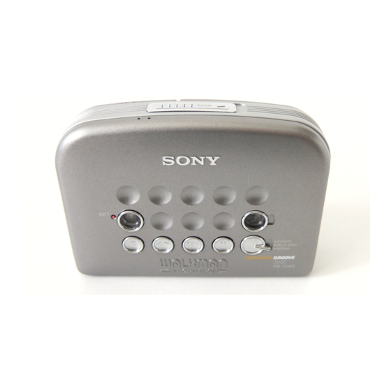
Photo : WM-EX404
× 1
inches) incl.
3/8
5/16
Model Name Using Similar Mechanism
Tape Transport Mechanism Type
Dolby noise reduction manufactured under license from Dolby Labo-
ratories Licensing Corporation.
"DOLBY" and the double-D symbol a are trademarks of Dolby
Laboratories Licensing Corporation.
Notes on Chip Component Replacement
• Never reuse a disconnected chip component.
• Notice that the minus side of a tantalum capacitor may be dam-
aged by heat.
Flexible Circuit Board Repairing
• Keep the temperature of the soldering iron around 270˚C during
repairing.
• Do not touch the soldering iron on the same conductor of the
circuit board (within 3 times).
• Be careful not to apply force on the conductor when soldering
or unsoldering.
– 1 –
AEP Model
E Model
NEW
MF-WMFX483-147
CASSETTE PLAYER
Advertisement
Table of Contents

Related Manuals for Sony WM-EX402


Summary of Contents for Sony WM-EX402
- Page 1 WM-EX402/EX404/EX405/EX406 SERVICE MANUAL AEP Model E Model Photo : WM-EX404 Model Name Using Similar Mechanism Tape Transport Mechanism Type MF-WMFX483-147 SPECIFICATIONS Tape section Frequency response (Dolby NR off) Playback: 40 - 14,000 Hz Headphones 2 jack Output Load impedance 8 - 300 ohms...
-
Page 2: Table Of Contents
TABLE OF CONTENTS 1. GENERAL Getting Started ................ 4 Operating the Walkman ............4 Additional Information ............4 2. DISASSEMBLY 2-1. Cabinet (Rear) Assy ............5 2-2. Main Board ................. 6 2-3. Mechanism Deck ..............6 2-4. Cassette Lid Sub Assy ............7 2-5. - Page 3 SECTION 1 GENERAL This section extracted from instruction manual. – 3 –...
- Page 4 – 4 –...
-
Page 5: Disassembly
SECTION 2 DISASSEMBLY • The equipment can be removed using the following procedure. Set / Cabinet (rear) assy Main board / Mechanism deck Cassette lid sub assy / Display board Note : Follow the disassembly procedure in the numerical order given. 2-1. -
Page 6: Main Board
2-2. MAIN BOARD 1 serrat IB lock MAIN board 3 flexible (MEGA BASS) board 2 flexible board (HEAD) cabinet (front) assy 2-3. MACHANISM DECK mechanism deck cabinet (front) assy – 6 –... -
Page 7: Cassette Lid Sub Assy
2-4. CASSETTE LID SUB ASSY 3 spring (lid up) • Use caution when installing the cassette holder assy Install the cassette holder with the spring (lid up) cassette lid sub assy as shown below in the drawing so that it fits into the holes on the cabinet front assy. -
Page 8: Mechanical Adjustments
SECTION 3 SECTION 4 MECHANICAL ADJUSTMENTS ELECTRICAL ADJUSTMENTS PRECAUTION PRECAUTION • Supplied voltage : 2.5 V 1. Clean the following parts with a denatured-alcohol-moistened • Switches and control position swab : playback head pinch roller TAPE switch : NORM capstan rubber belt GROOVE/MEGA BASS/ 2. - Page 9 • IC Block Diagrams IC301 LA4585M-TLM IC302 NJM2185AV-TE2 13 12 10 9 25 24 23 22 21 20 PRE2 PRE1 MIX IN (R) REV (L) WEIGHT REV (R) HP IN (R) BIAS FWD (R) CIRCUIT FWD (L) Ach BLOCK L.B.GAIN Bch BLOCK (same Ach) RIPPLE M.B.ON/OFF...
- Page 10 IC701 TMP47C243LM-FV81CS ACUMRATOR H REGISTER L REGISTER DATA MEMORY (RAM) PROGRAM FLAG COUNTER RAM ADDRESS BUFFER STACK PROGRAM MEMORY (ROM) HOLD OPERATION MODE INTERRUPTION INTERRUPTION CONTROL CIRCUIT PERMISSION PERMISSION DATA REGISTER MASTER F/F CONVERSION SYSTEM CONTROL CIRCUIT TABLE INTERRUPTION CONTROL CIRCUIT TIMING GENERATOR CLOCK GENERATOR 12BIT...
-
Page 11: Exploded Views
Some delay should be anticipated Example : FR : France model when ordering these items. KNOB, BALANCE (WHITE) ... (RED) Parts Color Cabinet’s Color 6-1. CASSETTE LID SECTION WM-EX405/EX406 WM-EX402/EX404 (EX404) (EX404) Ref. No. Part No. Description Remark Ref. No. -
Page 12: Cabinet Section
6-2. CABINET SECTION MF-WMFX483-147 Ref. No. Part No. Description Remark Ref. No. Part No. Description Remark 3-020-510-01 KNOB (HOLD) 3-020-507-01 CABINET (FRONT) (EX402) 3-318-203-51 SCREW (B1.7X12), TAPPING 3-020-507-11 CABINET (FRONT) (EX404) 3-020-509-01 LID, BATTERY CASE (EX402) 3-020-507-22 CABINET (FRONT) (EX405/EX406) 3-020-509-11 LID, BATTERY CASE (EX404) 3-364-675-01 SPRING (CASSETTE) 3-020-509-21 LID, BATTERY CASE (EX405/EX406) -
Page 13: Mechanism Deck Section
6-3. MECHANISM DECK SECTION (MF-WMFX483-147) M901 HP901 Ref. No. Part No. Description Remark Ref. No. Part No. Description Remark X-3375-020-1 LEVER ASSY (N-F), PINCH 3-703-816-31 SCREW (M1.4), SPECIAL HEAD X-3372-558-1 WHEEL ASSY (SP), CAPSTAN X-3375-021-1 LEVER ASSY (R-F), PINCH 3-354-868-11 BELT 3-703-816-73 SCREW (M1.4), SPECIAL HEAD 3-021-950-01 GEAR (DF) 3-921-797-01 WASHER... -
Page 14: Electrical Parts List
SECTION 7 DISPLAY MAIN ELECTRICAL PARTS LIST NOTE: • Due to standardization, replacements in • Items marked “*” are not stocked since When indicating parts by reference the parts list may be different from the they are seldom required for routine service. number, please include the board. - Page 15 MAIN Ref. No. Part No. Description Remark Ref. No. Part No. Description Remark C352 1-126-157-11 ELECT 10uF 1-216-864-11 METAL CHIP 1/16W (EXCEPT EX402) 1-216-295-00 SHORT C353 1-162-964-11 CERAMIC CHIP 0.001uF JC10 1-216-864-11 METAL CHIP 1/16W (EXCEPT EX402) JC11 1-216-295-00 SHORT C354 1-113-619-11 CERAMIC CHIP 0.47uF...
- Page 16 MAIN Ref. No. Part No. Description Remark Ref. No. Part No. Description Remark R207 1-216-807-11 METAL CHIP 1/16W < SWITCH > (FR) R208 1-216-841-11 METAL CHIP 1/16W S301 1-771-091-21 SWITCH, PUSH (1 KEY) (OPEN DET) R209 1-216-825-11 METAL CHIP 2.2K 1/16W S303 1-572-922-11 SWITCH, SLIDE (TAPE)
- Page 17 WM-EX402/EX404/EX405/EX406 Sony Corporation 98B0468-1 9-923-324-11 Personal A&V Products Company Printed in Japan C1998. 2 – 22 – Published by Quality Engineering Dept. (Shibaura)