Advertisement
Quick Links
Installation Instructions
Please make sure to read this manual before installation.
Safety Precautions
● Insert cables deep enough for ensuring a wire connection.
Inadequate insertion may produce heat, causing burnout or fire.
Must be followed
This product detects the presence of humans by measuring the temperature
distribution in the detection area and detecting the movement of objects that
have a higher temperature than the background.
Avoid installation in the following places.
* A human body may not be detected when the difference between its surface
temperature and the room temperature is small.
Near the air outlet of an air
conditioner, etc.
A place with highly reflective
floor surfaces
Wiring Diagram
■ RS485 Communication line wiring
Power
supply
( DC24V )
入力 送り 終端
+ − + − E
DC24V
DC24V
OND
OND
入力
送り
Control
device
D class grounding
• Use shielded twisted pair cables.
• The shield must be grounded at one end. Ground terminals are for grounding only
and require D class grounding.
• Use transition wiring for device connections. (Branch wiring not applicable)
■ Terminal arrangement
DC24V GND
DC24V GND
Power
Power
Contact output
supply
supply
(Input)
(Feed)
■ Applicable cables
Power cable
φ 0.65 to φ 0.9 Cu (copper) Single wire only
RS485 signal cable
φ 0.65 to φ 0.9 CPEV cable
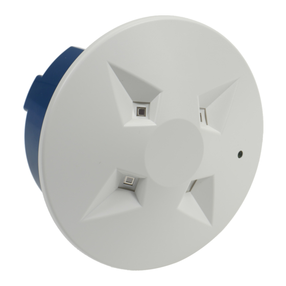
Infrared Array Sensor
Grid-EYE Unit Type
Please make sure to follow
Warning
A place with rapid temperature
changes
A place with an automated moving
object
A place where the floor temperature
is high due to sunlight, floor heating, etc.
A place with swinging objects
Input Feed Termination
Termination side
入力 送り 終端
+ − + − E
E
DC24V DC24V
OND
OND
入力
送り
The termination-side device's
feed and termination terminals
D class grounding
must be connected to each other.
+ −
+ −
E E
RS485
RS485 Termination
(Input)
(Feed)
10 mm
Advance Check Items and Installation Requirements
1. Avoid incorrect wire connections and short circuits.
2. Wipe off stains using soft, dry cloth without scratching.
Avoid using thinners, alkaline detergents, acid detergents, cleansers,
pesticides, etc. Their use may cause a failure.
Operation lamp
Illuminates red when a human
body is detected
Note: The detection range
varies depending on the
installation height.
Depth above the ceiling
surface: 50 mm or more
Claw part
Sensor
Removal
E
groove
* Check the detection
range after installation.
Area mask setting
switch (4-bit)
Reset switch
Press the reset switch
after setting changes.
AMGU4241
Model No.
Detection Range
▼Detection range (estimate) when the ceiling is 2.7 m high
● The ceiling height must be 2.7 m or lower.
The product cannot be used on a sloped ceiling.
How to Mount
+5
100
mm
φ
0
Ceiling board thickness:
30 mm or less
Clamping metal fitting
Lower the fitting to fix by
turning the screw with
a Philips screwdriver.
* Remove the protection
Note: Do not touch the
How to Remove the Cover
Turn right and left
Screwdriver
Removal groove
RS485 Address Setting
Binary numbers
32
16 8 4 2 1
ON
1
2
3
4
5
6
Address setting switch
(6-bit)
* Use binary numbers for address setting.
film attached to the sensor
surface before mounting
the cover.
sensor surface.
Cover
Cover
Ceiling surface
Example of address setting
Address: 1
ON
1
2
3
4
5
6
Address: 8
ON
1
2
3
4
5
6
Advertisement

Related Manuals for Panasonic AMGU4241


Summary of Contents for Panasonic AMGU4241
- Page 1 Infrared Array Sensor Grid-EYE Unit Type AMGU4241 Model No. Installation Instructions Please make sure to read this manual before installation. Advance Check Items and Installation Requirements Safety Precautions Please make sure to follow 1. Avoid incorrect wire connections and short circuits. 2. Wipe off stains using soft, dry cloth without scratching.
- Page 2 Device Solutions Business Division, Automotive & Industrial Systems Company, Panasonic Corporation 5 Ii, Awara-City, Fukui 919-0697, Japan 8A3 G97 0000 1...