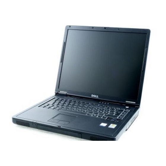
Dell Inspiron 7500 System Reference Manual
Hide thumbs
Also See for Inspiron 7500:
- Reference and troubleshooting manual (162 pages) ,
- Service manual (75 pages) ,
- Replacement manual (63 pages)
Table of Contents
Advertisement
Quick Links
Dell™ Inspiron™ 7500 System Reference
Conventions
Technical Overview
Using the Computer
Utilities and Drivers for Windows 98
Utilities and Drivers for Windows NT
Technical Specifications
Setup Program
System Codes and Messages
Passwords and Security
Ports and Connectors
Power Sources
Power Conservation
Removing and Replacing Parts
Documentation
Information in this document is subject to change without notice.
© 1999–2000 Dell Computer Corporation. All rights reserved.
Reproduction in any manner whatsoever without the written permission of Dell Computer Corporation is strictly forbidden. Trademarks used in this text: Dell, the DELL logo,
MegaBay, and Inspiron are trademarks of Dell Computer Corporation; Microsoft, Windows, MS-DOS, and Windows NT are registered trademarks of Microsoft Corporation;
Intel and Pentium are registered trademarks, and Celeron is a trademark of Intel Corporation; Adobe is a trademark of Adobe Systems Incorporated, which may be registered
in certain jurisdictions.
Other trademarks and trade names may be used in this document to refer to either the entities claiming the marks and names or their products. Dell Computer Corporation
disclaims any proprietary interest in trademarks and trade names other than its own.
Initial release: 20 Sep 1999
Last revised: 17 Aug 2000
Advertisement
Table of Contents

Related Manuals for Dell Inspiron 7500


Summary of Contents for Dell Inspiron 7500
- Page 1 Other trademarks and trade names may be used in this document to refer to either the entities claiming the marks and names or their products. Dell Computer Corporation disclaims any proprietary interest in trademarks and trade names other than its own.
- Page 2 Back to Contents Page 13.3-Inch LCD Brackets and Carrier Tray Removal: Dell™ Inspiron™ 7500 NOTICE: The metal on the carrier tray is sharp. Be careful not to cut yourself. This procedure assumes that you have removed the front bezel and the 13.3-inch LCD panel. To remove the brackets from the LCD panel, follow these steps: 1.
- Page 3 Back to Contents Page 13.3-Inch LCD Panel Removal: Dell™ Inspiron™ 7500 This procedure assumes that you have removed the front bezel. Follow these steps to remove the 13.3-inch LCD panel: 1. Remove the (8) 6-mm screws that secure the left and right LCD brackets to the front plastic cover.
- Page 4 14.1-Inch LCD Panel, Brackets, and Carrier Tray Removal: Dell™ Inspiron™ 7500 This procedure assumes that you have removed the front bezel. Follow these steps to remove the 14.1-inch LCD panel: 1. Remove the (8) 6-mm screws that secure the left and right LCD brackets to the front plastic cover. 2. Detach the CCFL cable from connector CN2 on the right side of inverter board.
- Page 5 Back to Contents Page 15-inch LCD Panel Removal: Dell™ Inspiron™ 7500 To remove the 15-inch LCD panel, perform the following steps: 1. Turn the computer over and remove the 4 screws from the bottom of the computer. 2. Turn the computer back over and open the display.
- Page 6 Back to Contents Page AC Adapter: Dell™ Inspiron™ 7500 ...
- Page 7 Back to Contents Page Audio Jacks: Dell™ Inspiron™ 7500 ...
- Page 8 You can connect speakers, a microphone, headphones, and record/playback devices such as cassette players, CD players, and VCRs to the audio connectors on the computer. The connectors are located directly under the PC Card slot. Dell recommends using amplified speakers for the best sound.
- Page 9 Back to Contents Page Audio Card and Audio Thermal Shield Removal: Dell™ Inspiron™ 7500 ****New artwork pending This procedure assumes that you have removed the system board from the plastic case and have removed the PC Card cage from the system board. To remove the audio card and audio thermal shield, follow these steps: 1.
- Page 10 Back to Contents Page Component Locations (Back View): Dell™ Inspiron™ 7500...
- Page 11 Back to Contents Page Base Assembly Component Removal: Dell™ Inspiron™ 7500 Base Assembly Base Assembly Component Removal Base Assembly ****New artwork pending Base Assembly Component Removal The following procedures assume that the keyboard, thermal shield, display assembly, and palmrest assembly have been removed.
- Page 12 Back to Contents Page Battery Charge Gauge: Dell™ Inspiron™ 7500 ...
- Page 13 Back to Contents Page Removing and Installing a Battery: Dell™ Inspiron™ 7500 ...
- Page 14 Back to Contents Page Front Bezel Removal: Dell™ Inspiron™ 7500 This procedure assumes that you have removed the display assembly from the computer base. To remove the front bezel, follow these steps: 1. Use a dental pick to pry the rubber screw covers off of the bottom 2 screws and the rubber bumpers off of the top 2 screws.
-
Page 15: Storage Devices
Back to Contents Page Using the Computer: Dell™ Inspiron™ 7500 Storage Devices Touch Pad Audio Devices PC Cards Embedded Numeric Keypad External Monitor External Keyboard, Keypad, or Mouse Storage Devices Removing and Installing a Device in the Media Bay The media bay holds a second battery, a combination CD-ROM drive/diskette drive, a combination DVD-ROM drive/diskette drive, a combination DVD-ROM drive/LS-120 diskette drive, or an optional hard-disk drive. - Page 16 NOTE: The computer's BIOS may not support hard-disk drives obtained from vendors other than Dell. Dell does not guarantee compatibility or provide support for hard-disk drives obtained from other sources. To install a hard-disk drive, perform the following steps. NOTICE: To prevent data loss, shut down your computer before removing or installing your hard-disk drive. Do not remove the hard-disk drive if the computer is in suspend mode or save-to-disk mode or if the hard-disk drive access indicator is lit.
-
Page 17: Audio Devices
7. Tighten the screws you loosened in step 3. 8. Test the drive by running the Hard-Disk Drives (Non-SCSI) test group in the Dell Diagnostics. For information on running the diagnostics, see "Running the Dell Diagnostics" in Chapter 3 of the Dell Inspiron 7500 Reference and Troubleshooting Guide. -
Page 18: Touch Pad
Attach a PS/2 mouse to the PS/2-compatible connector on the computer (see Figure 6) or a USB-compatible mouse to the USB connector. If you attach a USB mouse to the computer, you do not need to reboot the computer in order to use the mouse. The touch pad device drivers that Dell installed on your hard-disk drive work with a PS/2 mouse, serial mouse, or USB mouse from Dell. - Page 19 Both PC Card slots support CardBUS technology. In addition, a zoomed video (ZV) port is available from the lower slot (slot 0). If you ordered an Moving Pictures Experts Group (MPEG)-2 decoder PC Card from Dell, install it in the lower PC slot for high-performance graphics.
-
Page 20: External Monitor
One Type I card and one Type II card (using either connector) Two Type I cards or two Type II cards A single Type III card (using the bottom connector) The type of card refers to its thickness, not its functionality. Because a Type III card is thicker than Type I and Type II cards, it takes up the entire PC Card slot, although it uses only one PC Card connector. - Page 21 NOTE: When the external monitor and built-in display are used simultaneously, the refresh rate is always 60 hertz (Hz). Back to Contents Page...
-
Page 22: Notes, Notices, And Cautions
Back to Contents Page Conventions: Dell™ Inspiron™ 7500 Notes, Notices, and Cautions Typographical Conventions The following subsections describe notational conventions used in this document. Notes, Notices, and Cautions Throughout this guide, blocks of text may be accompanied by an icon and printed in bold type or in italic type. These blocks are notes, notices, and cautions, and they are used as follows: NOTE: A NOTE indicates important information that helps you make better use of your computer system. - Page 23 Back to Contents Page DC-DC Board Removal: Dell™ Inspiron™ 7500 To remove the DC-DC board, gently pull the DC-DC board off of connectors JP11 and JP16 on the system board. Do not rock the board to remove it, because this may damage the connectors.
- Page 24 Back to Contents Page Display Assembly and Display Assembly Component Removal: Dell™ Inspiron™ 7500 Display Assembly Removal Display Assembly Component Removal Display Assembly Removal This procedure assumes that you have removed the keyboard thermal shield. The following procedure applies to all LCD displays (15-inch XGA, 15-inch SXGA+, and 15.4-inch SXGA).
-
Page 25: Printed Documentation
To view a PDF file, launch Acrobat Reader. Click File–> Open and select the PDF file. Right-click only the following links: Getting Started (.pdf) (835 KB) Dell Inspiron 7500 System Reference and Troubleshooting Guide (.pdf) (1993 KB) Dell Inspiron 7500 System Port Replicator User's Guide (.pdf) ( 3051 KB) Dell Inspiron Systems Setup Guide (.pdf) (670 KB) - Page 26 Back to Contents Page...
- Page 27 Back to Contents Page Drivers: Dell™ Inspiron™ 7500 Reinstalling Utilities and Drivers for Windows 98 Reinstalling Utilities and Drivers for Windows NT ...
-
Page 28: Installing The Windows 98 Operating System
Overview This section explains how to install/reinstall Dell device drivers and utilities on your Dell computer running the Microsoft Windows 98 Second Edition operating system. You may need to use this information under the following conditions: You are reinstalling the version of the Windows operating system that came with your computer, and you need to reinstall the drivers and utilities that Dell provides. - Page 29 The touch pad driver controls features such as touch pad and mouse functions, scrolling, touch features, and sensitivity. NOTE: When you are promoted to select a directory, Dell recommends using the default directory settings. 1. Save and close any open files, and exit any open application programs.
- Page 30 NOTE: When you are promoted to select a directory, Dell recommends using the default directory settings. 1. Insert the Dell Inspiron 7500 Software DVD Decoder CD into the CD-ROM or DVD-ROM drive. 2. Click the Start button, and then click Run.
-
Page 31: Installing The System Help
<Enter>. 9. Remove the System Software CD, and press <Ctrl><Alt><Delete> to restart the system. Installing the System Help The Dell Inspiron system Help is available on the System Software CD. You can also access it from the Documentation page. -
Page 32: Creating The Save-To-Disk Suspend Partition
1. Insert the Dell Diagnostics and Utilities for Inspiron 7500 diskette number 1 into the diskette drive and turn on the computer. 2. When the message Insert Delldiag diskette 2 of 4 in drive A:... appears, type C to exit to MS-DOS®. Leave the Dell Diagnostics and Utilities for Inspiron 7500 diskette number 1 in the diskette drive. -
Page 33: Installing The Audio Driver
1. Save and close any open files, and exit any open application programs. 2. Insert the System Software CD into the CD-ROM or DVD-ROM drive. 3. Double-click the My Computer icon, and then double-click the CD-ROM drive icon. 4. Double-click the WinNT folder, then double-click the Video folder. 5. - Page 34 5. Double-click Setup. 6. In the Welcome window, click Next. 7. In the Important Information window, click Next. Another Important Information window appears recommending that you create or update an emergency repair diskette before you install the touch pad driver. 8.
- Page 35 7. When prompted, select the Yes, I want to restart my computer now check box and click Finish to restart the computer. Installing the System Help The Dell Inspiron system Help is available on the System Software CD. You can also access it from the Documentation page.
- Page 36 4. Right-click and hold 7500help and drag it to the Windows® desktop. 5. Release the right mouse button. 6. Left-click Copy Here. 7. Double-click the 7500help icon to access the system Help. Back to Contents Page...
- Page 37 Back to Contents Page Using an External Monitor: Dell™ Inspiron™ 7500 Use the 15-pin video connector to attach an external monitor to the computer. If you reconfigure your hardware, you may need pin number and signal information for the monitor connector. Use the following procedure to connect an external monitor: 1.
- Page 38 Exploded View of 13.3-Inch Display Assembly: Dell™ Inspiron™ 7500...
- Page 39 Exploded View of 14.1-Inch Display Assembly: Dell™ Inspiron™ 7500...
- Page 40 Back to Contents Page Exploded View of 15-Inch SXGA+ Display Assembly: Dell™ Inspiron™ 7500 ****New artwork pending...
- Page 41 Back to Contents Page Exploded View of 15-Inch XGA Display Assembly: Dell™ Inspiron™ 7500 ****New artwork pending Back to Contents Page...
- Page 42 Back to Contents Page Exploded View of 15.4-Inch SXGA Display Assembly: Dell™ Inspiron™ 7500 ****New artwork pending...
- Page 43 Back to Contents Page Exploded View of Base Assembly: Dell™ Inspiron™ 7500 ****New artwork pending Back to Contents Page...
- Page 44 Back to Contents Page Exploded View of Computer: Dell™ Inspiron™ 7500...
- Page 45 Back to Contents Page Exploded View of Palmrest Assembly: Dell™ Inspiron™ 7500 Back to Contents Page...
- Page 46 Attach a PS/2 mouse to the PS/2-compatible connector on the computer or a USB-compatible mouse to the USB connector. If you attach a USB mouse to the computer, you do not need to reboot the computer in order to use the mouse. The touch pad device drivers that Dell installed on your hard-disk drive work with a PS/2 mouse, serial mouse, or USB mouse from Dell.
- Page 47 Back to Contents Page Component Locations (Front View): Dell™ Inspiron™ 7500 ****New artwork pending ...
- Page 48 The Inspiron 7500 contains many screws of various sizes. To help keep track of the screws, use a tackle or pill box as a storage device. Use the following location template to store the screws during disassembly.
- Page 49 Back to Contents Page Graphics: Dell™ Inspiron™ 7500 Status Display Component Locations (Front View) Component Locations (Back View) AC Adapter Removing and Installing a Battery From the MegaBay Battery Charge Gauge Removing Devices From the Media Bay Removing the Hard-Disk Drive Removing the Memory Module...
- Page 50 Back to Contents Page Hard-Disk Drive Disassembly: Dell™ Inspiron™ 7500 The hard-disk drive resides in a carrier that mounts in the hard-disk drive compartment in the bottom of the computer. 4 screws secure the drive inside the carrier. To remove the hard-disk drive from the carrier, follow these steps: 1.
- Page 51 Back to Contents Page Hard-Disk Drive Heat Shield Removal: Dell™ Inspiron™ 7500 This procedure assumes that you have removed the palmrest assembly from the base assembly. To remove the hard-disk drive heat shield, follow these steps: 1. Place the palmrest assembly face down. 2. Remove the (5) 4-mm screws securing the hard-disk drive heat shield.
- Page 52 Back to Contents Page Heat Exchanger/Fan Removal: Dell™ Inspiron™ 7500 ****New artwork pending To remove the heat exchanger/fan, follow these steps: 1. Remove the (2) 5-mm screws securing the heat exchanger. 2. Disconnect the fan cable from connector JP17 on the system board. 3. Remove the heat exchanger/fan.
- Page 53 Back to Contents Page Hinge Saddle Removal: Dell™ Inspiron™ 7500 ****New artwork pending This procedure assumes that you have removed the PC Card heat sink. To remove the hinge saddles, follow these steps: 1. Remove the (4) 4-mm screws from the top of the left and right hinge saddles.
- Page 54 Back to Contents Page I/O Connectors: Dell™ Inspiron™ 7500...
-
Page 55: Infrared Port
The infrared port allows the transfer of files from one computer to another infrared- compatible device, without using cable connections. Dell has installed data communications software for you to use with your infrared port. You can also use other commercially available infrared-capable application programs. -
Page 56: Serial Connector
Serial Connector Use the 9-pin serial connector to attach a serial device to the computer. The serial port passes data in serial format (1 bit at a time over one line). This port supports a variety of devices, including a serial mouse, that require serial data transmission. If you reconfigure your hardware, you may need pin number and signal information for the serial connector. -
Page 57: Monitor Connector
BUSY Busy Paper end SLCT Select AFD# Automatic feed ERR# Error INIT# Initialize printer SLIN# Select in 18–25 Signal ground Shell Frame ground Monitor Connector Use the 15-pin monitor connector to attach an external monitor to the replicator. If the image does not appear on the monitor immediately, press <Fn><F8>. - Page 58 Signal Definition EXK_MSDATA External keyboard/keypad/mouse data No connection Signal ground EXK_MSPWR External keyboard/keypad/mouse supply voltage EXK_MSCLK External keyboard/keypad/mouse clock No connection Shell Chassis ground TV-Out S-Video Connector If the television has an S-video cable, plug it directly into the system at the S-video TV-out connector. If the television has a composite cable, complete the following steps: 1.
- Page 59 Back to Contents Page IR Board Removal: Dell™ Inspiron™ 7500 This procedure assumes that you have removed the palmrest assembly from the base assembly. To remove the IR board, follow these steps: 1. Remove the (2) 4-mm screws securing the IR board. 2. Disconnect the IR cable from connector JP2 on the IR board.
- Page 60 Back to Contents Page 30° Cone of Infrared Light: Dell™ Inspiron™ 7500 ...
-
Page 61: Controls And Indicators
Back to Contents Page Jumpers, Switches, Controls, and Indicators: Dell™ Inspiron™ 7500 Jumpers Switches Controls and Indicators Jumpers There are no jumpers on this system. Switches There are no configuration switches on this system. Controls and Indicators Front View Status Lights 3 status lights are located in the indicator panel directly above the keyboard: Num Lock: Solid green light when Num Lock is on. - Page 62 Battery Charge Gauge The battery charge gauge on the rear of the main and secondary batteries has 5 charge-level indicator lights that indicate how much battery charge remains. Each light indicates approximately 20% battery charge. Press the status button to the right of the lights to check the total battery charge. If none of the lights are on, the battery has no charge left.
- Page 63 Back to Contents Page Keyboard Removal: Dell™ Inspiron™ 7500 ****New artwork pending To remove the keyboard, follow these steps: 1. Turn the computer over and remove the (4) 20-mm screws from the bottom of the computer. 2. Turn the computer back over and open the display.
- Page 64 Back to Contents Page Embedded Numeric Keypad: Dell™ Inspiron™ 7500 ...
- Page 65 Back to Contents Page Latch Assembly Removal: Dell™ Inspiron™ 7500 To remove the latch assembly, follow these steps: 1. Disconnect the LED cable from connector JP2 on the LED board. 2. Remove the 4-mm screw securing the LED board to the plastic base. 3. Remove the LED board.
- Page 66 LVDS Board Removal: Dell™ Inspiron™ 7500 To remove the LVDS board, follow these steps: 1. Remove the 4-mm screw securing the LVDS board. 2. Gently pull the LVDS board off of connectors JP9 and JP8 on the system board. Do not rock the board to remove it, because this may damage the connectors.
- Page 67 Back to Contents Page System Board Removal: Dell™ Inspiron™ 7500 ****New artwork pending This procedure assumes that you have removed the PC Card heat sink hinge saddles. To remove the system board, follow these steps: 1. Remove the (3) 4-mm screws from the bottom of the computer.
-
Page 68: Memory Installation Guidelines
256 MB 256 MB 512 MB *Not all valid memory configurations are available at all times. Contact Dell for details. Removing and Installing Memory Memory modules for your computer are available in 32-, 64-, 128-, 192-, and 256-megabyte (MB) sizes. - Page 69 Dell (but which Dell does not install), except the 192-MB memory module, in either socket. If you purchase a non-Dell-installed 192- MB memory module, you must install it in slot 2. To install memory module(s), perform the following steps.
-
Page 70: Creating The Save-To-Disk Suspend File
No error message or beep code indicates this failure. 13. Run the System Memory device group in the Dell Diagnostics to confirm that the installed memory modules are operating correctly. For instructions, see Chapter 3, “Running the Dell Diagnostics” in the Dell Inspiron 7500 System Reference and Troubleshooting Guide. -
Page 71: Conventional Memory Map
Location Description 10FFF0– Extended memory 100000–10FFEF High memory area 0F0000–0FFFFF System BIOS 0E0000–0EFFFF Video BIOS 0DC000–0DFFFF Available 0D0000–0DBFFF PC Card memory 0C0000–0CFFFF Available 0A0000–0BFFFF Video RAM 09FC00–09FFFF PS/2 mouse-data area 000000–09FBFF Conventional memory Conventional Memory Map Segment Address Range 00000h–003FFh Interrupt vector table 00400h–004FFh BIOS data area... - Page 72 Back to Contents Page Combo Module Disassembly: Dell™ Inspiron™ 7500 The combo module contains either a CD-ROM drive, a DVD-ROM drive on top of a diskette drive, or DVD-ROM drive with a SuperDisk LS-120 module. The combo module resides in a carrier that slides into the Media bay on the left side of the computer.
- Page 73 When reassembling the diskette drive, be sure that the bottom of the metal shielding carrier sits inside the groove at the front of the plastic carrier. Back to Contents Page...
- Page 74 Back to Contents Page Tech Notes: Dell™ Inspiron™ 7500 Video Memory Power Sources Storage Devices Touch Pad Audio Devices PC Cards Using the Embedded Numeric Keypad Using an External Monitor Using an External Keyboard, Keypad, or Mouse Power Conservation Passwords and Security...
- Page 75 Back to Contents Page Using the Embedded Numeric Keypad: Dell™ Inspiron™ 7500 As you work, you may want to use the embedded numeric keypad to enter numbers into a spreadsheet or financial program. The embedded numeric keypad shares some of the keys on the computer's keyboard. The embedded keypad numbers and symbols are marked on the right of the keypad keys in blue.
- Page 76 Back to Contents Page Technical Overview: Dell™ Inspiron™ 7500 Video Memory Controls and Indicators Video Table 1. Text Mode Resolution Color Depth Maximum Refresh Rate (Hz) 360 x 400 720 x 400 720 x 400 mono Table 2. Graphics Modes...
- Page 77 1024 x 768 256 colors 1024 x 768 16 bit 1024 x 768 24 bit 1024 x 768 32 bit 1280 x 1024 256 colors 1280 x 1024 16 bit 1280 x 1024 24 bit 1280 x 1024 32 bit 1400 x 1050 256 colors 1400 x 1050...
- Page 78 NOTE: Your computer has two memory module sockets (slot 1 and slot 2). You can install all sizes of memory modules you purchase from Dell (but which Dell does not install), except the 192-MB memory module, in either socket. If you purchase a non-Dell-installed 192-MB memory module, you must install it in slot 2.
- Page 79 No error message or beep code indicates this failure. 13. Run the System Memory device group in the Dell Diagnostics to confirm that the installed memory modules are operating correctly. For instructions, see “Running the Dell Diagnostics” in Chapter 3 of the Dell Inspiron 7500 System Reference and Troubleshooting Guide.
- Page 80 Segment Address Range 00000h–003FFh Interrupt vector table 00400h–004FFh BIOS data area 00500h–005FFh MS-DOS® work area 00600h–0FFFFh User memory 10000h–1FFFFh User memory 20000h–2FFFFh User memory 30000h–3FFFFh User memory 40000h–4FFFFh User memory 50000h–5FFFFh User memory 60000h–6FFFFh User memory 75000h–7FFFFh User memory 80000h–8FFFFh User memory 90000h–9FBFFh User memory 9FC00h–9FFFFh...
- Page 81 Figure 4. Component Locations (Back View) 1 Speakers 2 PC card slot 3 Audio connectors 4 AC adapter connector 5 Infrared port 6 PS/2 connector 7 USB connector 8 Docking connector 9 TV-out S-video connector 10 Video connector 11 Serial port connector 12 Parallel port connector 13 Fan exhaust Three status lights (see Figure 5) are located in the indicator panel directly above the keyboard:...
- Page 82 Blinking green light when the battery is charging. ¡ No light when the battery is discharging or if the battery is not installed. ¡ Solid amber light when the battery charge is low (7% life remaining). ¡ Blinking amber light when the battery charge is critically low (1.5% life remaining). The system beeps when this level is first reached. ¡...
-
Page 83: Palmrest Assembly Removal
Back to Contents Page Palmrest Assembly and Palmrest Assembly Component Removal: Dell™ Inspiron™ 7500 Palmrest Assembly Removal Palmrest Assembly Component Removal To remove the internal modem card, follow these steps: 1. Gently pull the modem card off of connector JP19 on the system board. Do not rock the card to remove it, because this may damage the connectors. -
Page 84: Palmrest Assembly Component Removal
palmrest assembly snaps into place. Start at the front to align those tabs first. Make sure that all the tabs are aligned. Palmrest Assembly Component Removal IR Board Removal Hard-Disk Drive Heat Shield Removal Touch Pad Assembly Removal Speaker Removal Back to Contents Page... -
Page 85: About Passwords
Back to Contents Page Passwords and Security: Dell™ Inspiron™ 7500 About Passwords Physically Securing the Computer Disabling the Serial and Parallel Ports About Passwords When you receive the computer, the password features are disabled so that you can assign passwords if you wish. Once you assign a password, you must enter the password to access the Setup program. - Page 86 Back to Contents Page PC Card Cage Removal: Dell™ Inspiron™ 7500 ****New artwork pending This procedure assumes that you have removed the system board from the plastic case. To remove the PC Card cage, follow these steps: 1. Remove the 4-mm screw securing the audio bezel.
- Page 87 Both PC Card slots support CardBUS technology. In addition, a ZV port is available from the lower slot (slot 0). If you ordered an MPEG-2 decoder PC Card from Dell, install it in the lower PC slot for high-performance graphics.
- Page 88 system. You can also double-click the PC Card icon on the Windows 98 desktop. Back to Contents Page...
- Page 89 Back to Contents Page PC Card Slots: Dell™ Inspiron™ 7500...
- Page 90 Back to Contents Page PC Card Heat Sink Removal: Dell™ Inspiron™ 7500 To remove the PC Card heat sink, follow these steps: 1. Remove the (2) 4-mm screws securing the PC Card heat sink. 2. Remove the heat sink.
- Page 91 For information on configuring the standard infrared drivers that come with Microsoft® Windows® 98, see your operating system documentation. To install the fast infrared drivers provided by Dell, see the instructions in the readme.doc file on your System Software CD. If for some reason you need to change the infrared port address, be careful not to create a conflict with the addresses of the serial port or the parallel port.
- Page 92 NOTE: Make sure that there are no books, papers, or other objects between the two infrared devices and that the two devices are within the 30° cone. Modem Port The Modem Port option appears only if your computer has an integrated modem. This option allows you to map the address of the port to avoid address conflicts with other devices.
- Page 93 Table 2. Serial Connector Pin Assignments Signal Definition Data carrier detect RXDA Receive data TXDA Transmit data Data terminal ready Signal ground Data set ready Request to send Clear to send Ring indicator Shell Frame ground Parallel Connector Use the 25-hole parallel connector (see Figure 5) to attach a parallel device to the computer. The parallel connector is used primarily for printers. The parallel port sends and receives data in parallel format, where 8 data bits (one byte) are sent simultaneously over eight separate lines.
- Page 94 SLCT Select AFD# Automatic feed ERR# Error INIT# Initialize printer SLIN# Select in 18–25 Signal ground Shell Frame ground Monitor Connector Use the 15-pin monitor connector (see Figure 6) to attach an external monitor to the replicator. If the image does not appear on the monitor immediately, press <Fn><F8>.
- Page 95 Table 5. PS/2 Connector Pin Assignments Signal Definition EXK_MSDATA External keyboard/keypad/mouse data KBD_DATA Keyboard data Signal ground EXK_MSPWR External keyboard/keypad/mouse supply voltage EXK_MSCLK External keyboard/keypad/mouse clock KBD_CLK Keyboard Clock Shell Chassis ground TV-Out S-Video Connector If the television has an S-video cable, plug it directly into the system at the TV-out S-video connector. If the television has a composite cable, perform the following steps: 1.
- Page 96 U.S., you may need to obtain a power cable designed for use in that country. NOTICE: The AC adapter is designed to work only with Dell Inspiron portable computers. Do not use adapters from other computers, and do not attempt to use this adapter with other computers.
-
Page 97: Charging The Battery
2. Shut down the computer. 3. Close the display and turn the computer over. 4. Remove the main battery (see Figure 2). Press the latch lock toward the back of the computer and slide the latch release away from the battery. Hold the latch release with one hand and pull the battery out of the MegaBay. - Page 98 1. Connect the computer to the AC adapter. 2. Install the main battery and/or a second battery in the computer. The battery starts charging immediately. The battery light-emitting diode (LED) on the front of the computer appears as a solid green light while the battery is charging.
- Page 99 When you received your computer, the Low battery and Critical battery alarms check boxes were not checked. Dell recommends that you do not select these options. Power Meter allows you to view the percentage of battery life remaining when your system is operating on battery power. When your computer is not operating on battery power, it displays a message indicating that your computer is operating on AC power.
- Page 100 Using Windows NT to Conserve Battery Power To access the Power Management Control window (see Figure 2) and set the power management features in Windows NT, perform the following steps: 1. Click the Start button, point to Settings, and click Control Panel. 2.
-
Page 101: Standby Mode
NOTE: Save-to-disk suspend mode requires a special file on your hard-disk drive that sets aside enough disk space to store the contents of the computer's memory. Dell creates an appropriately sized save-to-disk suspend file before shipping the computer to you. If you remove the file or add memory to the computer, or if your hard-disk drive becomes corrupted, you must recreate the file before you can again use save-to-disk suspend mode. - Page 102 Back to Contents Page Processor Board Removal: Dell™ Inspiron™ 7500 ****New artwork pending This procedure assumes that you have removed the heat exchanger/fan. To remove the processor board, follow these steps: 1. Remove the (3) 5-mm screws securing the processor board to the system board.
- Page 103 Back to Contents Page Removing the Memory Module: Dell™ Inspiron™ 7500 ...
- Page 104 Back to Contents Page Removing the Memory Module Cover: Dell™ Inspiron™ 7500...
-
Page 105: Precautionary Measures
Back to Contents Page Removing and Replacing Parts: Dell™ Inspiron™ 7500 NOTICE: Only a certified service technician should perform the procedures for removing and replacing parts. The warranty on the computer becomes void if anyone other than a certified technician performs these procedures. Overview 15-Inch LCD Removal Precautionary Measures 15.4-Inch LCD Removal... - Page 106 1. Determine the power state of the computer. If the system is on, go to step 2. If you are unsure whether the system is on, shut down and restart the system, and then go to step 2. 2. Turn off any attached peripherals, and then shut down the computer. 3.
- Page 107 2 Battery 3 Latch release 6. Remove PC Cards (see Figure 4). NOTICE: Use the PC Card configuration utility on the taskbar to select and stop a card before removing it from the computer. If you do not remove the card in the configuration utility, you could lose data from open application programs. To remove PC Cards from the top connector, press the top eject button.
- Page 108 3 Captive screws (2) 8. Remove the memory module and video card covers (see Figure 6). Slide each cover as far as it will go in the direction of the arrow, and then remove the cover. Figure 6. Memory Module and Video Card Covers 1 Video card cover 2 Memory module cover To replace a cover, place it over the opening, leaving a small gap along the rounded edge, and then slide the cover toward the outside...
-
Page 109: Recommended Tools
1 3-mm screws (2) 2 Video card 3 Video card connectors (2) 11. If present, remove the device from the media bay (see Figure 9). Unlock the latch lock by flipping it toward the back of the computer. Slide the latch release in the direction of the arrow. Keep holding the latch release with one hand while pulling the combo module or second battery straight out of the media bay with the other. -
Page 110: Screw Identification And Tightening
Kapton tape correctly to retain the electrical protection and noise reduction the tape provides. Be careful not to scratch the computer plastic case by allowing screws to get between the disassembly surface and the plastic case. Dell suggests a soft padded work surface. -
Page 111: Exploded View Of 15-Inch Xga Display Assembly
1 Hard-disk drive 2 Battery 3 Combo module 4 Thermal shield 5 Keyboard 6 Display assembly 7 Hinge covers Exploded View of 15-Inch XGA Display Assembly Figure 11. 15-Inch XGA Display Components... -
Page 112: Exploded View Of 15-Inch Sxga+ Display Assembly
1 LCD panel 2 CCFL cable 3 Carrier tray 4 Back cover 5 Hinges (2) 6 Inverter board 7 Front bezel Exploded View of 15-Inch SXGA+ Display Assembly Figure 12. 15-Inch SXGA+ Display Components... -
Page 113: Exploded View Of 15.4-Inch Sxga Display Assembly
1 LCD panel 2 CCFL cable 3 Carrier tray 4 Display locking tab 5 Back cover 6 Hinges (2) 7 Inverter board 8 Front bezel Exploded View of 15.4-Inch SXGA Display Assembly Figure 13. 15.4-Inch SXGA Display Components... -
Page 114: Hard-Disk Drive Disassembly
1 LCD panel 2 CCFL cable 3 Display locking tab 4 Carrier tray 5 Back cover 6 Hinges (2) 7 Inverter board 8 Front bezel Hard-Disk Drive Disassembly The hard-disk drive (see Figure 14) resides in a carrier that mounts in the hard-disk drive compartment in the bottom of the computer. Four screws secure the drive inside the carrier. -
Page 115: Combo Module Disassembly
3 3-mm screws (4) 4 Hard-disk drive 5 Carrier To remove the hard-disk drive from the carrier, perform the following steps: 1. Remove the hard-disk drive assembly. See step 7 of Precautionary Measures. 2. Remove the four 3-mm screws securing the hard-disk drive inside the carrier. 3. - Page 116 3. Remove the bracket. 4. Remove the two 3-mm screws from the side of the plastic carrier. 5. Remove the two 3-mm screws from the bottom of the plastic carrier. 6. Disconnect the flex cable from the CD-ROM/DVD-ROM drive connector. 7.
-
Page 117: Keyboard Removal
Keyboard Removal Figure 17. Keyboard Components 1 20-mm screws (4) 2 Palmrest assembly 3 ZIF connector 4 Keyboard cable 5 Keyboard To remove the keyboard (see Figure 17), perform the following steps: 1. Turn the computer over and remove the four 20-mm screws from the bottom of the computer. 2. -
Page 118: Thermal Shield And Internal Modem Removal
NOTICE: ZIF connectors are fragile. To avoid breaking the connectors, touch them carefully. Do not apply too much pressure to the movable part of the connector when opening or closing it. Some of the computer’s interface connectors are ZIF connectors. These connectors are not removable; they must be released (see Figure 18) to disconnect a cable from them. -
Page 119: Heat Exchanger/Fan Removal
This procedure assumes that you have removed the keyboard. To remove the thermal shield, perform the following steps: 1. Remove the right hinge cover. 15-Inch XGA and 15-Inch SXGA+ LCD Panels a. Open the computer to 170 degrees, supporting the display assembly. b. -
Page 120: Processor Board Removal
1. Remove the two 5-mm screws securing the heat exchanger. 2. Disconnect the fan cable from the connector labeled JP17 on the system board. 3. Remove the heat exchanger/fan. 4. Inspect the two thermal pads on the bottom of the heat exchanger and replace them if necessary. To remove the heat exchanger/fan without removing the palmrest assembly, perform the following steps: 1. - Page 121 1 LCD wire harness 2 Connector JP3 3 Hinge saddles (2) 4 Hinges (2) 5 6-mm screws (4) 6 Left hinge cover This procedure assumes that you have removed the keyboard, thermal shield, and right hinge cover. To remove the 15-inch LCD panel (see Figure 22), perform the following steps: 1.
-
Page 122: Palmrest Component Assembly
1 LCD wire harness 2 Connector JP3 3 Hinge saddle extensions (2) 4 Hinges (2) 5 6-mm screws (4) 6 Center cover 7 Left hinge cover 8 6-mm screws (3) 9 Screw covers (4) 10 5-mm screw (1) This procedure assumes that you have removed the keyboard, thermal shield, and right hinge... - Page 123 1 Display latch 2 Touch pad 3 Touch pad bracket 4 Right speaker 5 Hard-disk drive heat shield 6 Touch pad button board 7 Left speaker cover 8 Speakers (2) 9 Speaker wiring harness 10 Display latch 11 Palmrest 12 IR board Palmrest Assembly Removal Figure 25.
- Page 124 1 LED cable 2 6-mm screws (4) 3 LED connector 4 DC-DC board 5 Battery compartment/MegaBay 6 Hard-disk drive bay 7 4-mm screws (6) 8 Combo bay 9 Base assembly 10 Connector for speaker wiring harness 11 Palmrest assembly 12 Speaker wiring harness and grounding strap 13 Washer 14 4-mm screw...
- Page 125 This wire harness also contains wiring for the touch pad and the touch pad buttons. 10. Disconnect the LED cable from connector JP10 on the system board. 11. Remove the palmrest assembly from the base assembly. Start at the back right of the computer and move forward around the computer. Carefully lift the palmrest assembly up and pull it forward to unsnap the hidden tabs spaced around the sides and along the top of the MegaBay and media bay.
- Page 126 1 Touch pad bracket 2 4-mm screws (4) 3 Touch pad flex cable 4 ZIF connector 5 4-mm screws (3) 6 Touch pad button board 7 Touch pad This procedure assumes that you have removed the palmrest assembly from the base assembly and that you have removed the hard-disk drive heat shield.
- Page 127 1 4-mm screws (5) 2 Hard-disk drive heat shield This procedure assumes that you have removed the palmrest assembly from the base assembly. To remove the hard-disk drive heat shield (see Figure 29), perform the following steps: 1. Place the palmrest assembly face down. 2.
-
Page 128: Pc Card Heat Sink Removal
3. Remove the left speaker cover, speaker, and speaker cable. 4. Remove the speaker wire harness. 5. Remove the two 4-mm screws securing the right speaker cover. 6. Remove the right speaker cover, speaker, and speaker cable. The display latch is no longer secured by the speaker covers. Be careful not to lose the spring. 7. -
Page 129: Hinge Saddle Removal
1 DC-DC board To remove the DC-DC board (see Figure 32), gently pull the DC-DC board off of connectors JP11 and JP16 on the system board. Do not rock the board to remove it, because this may damage the connectors. Hinge Saddle Removal Figure 33. -
Page 130: Card Removal
4. Remove the 10-mm screw and 20-mm screw from the left hinge saddle and remove the saddle. 5. Disconnect the LED cable from connector J6 on the system board. 6. Remove the 6-mm screw from the plastic frame, remove any tape, and remove the plastic frame. RJ-11 Card Removal Figure 34. -
Page 131: Pc Card Cage Removal
PC Card Cage Removal Figure 36. PC Card Cage Components 1 4-mm screw 2 PC card cage 3 System board 4 18-mm screws (4) 5 Audio bezel This procedure assumes that you have removed the system board from the plastic case. To remove the PC Card cage (see Figure 36), perform the following steps: 1. -
Page 132: Latch Assembly Removal
1 10-mm screw 2 Audio thermal shield 3 Audio card This procedure assumes that you have removed the system board from the plastic case and have removed the PC Card cage from the system board. To remove the audio card and audio thermal shield (see Figure 37), perform the following these steps: 1. -
Page 133: Display Assembly Component Removal
1 LCD wire harness 2 Connector JP3 3 Hinge saddles (2) 4 Hinges (2) 5 6-mm screws (4) 6 Left hinge cover This procedure assumes that you have removed the keyboard thermal shield. The following procedure applies to all LCD displays (15-inch XGA, 15-inch SXGA+, and 15.4-inch SXGA). -
Page 134: Exploded View Of Base Assembly
This procedure assumes that you have removed the display assembly from the computer base. To remove the front bezel (see Figure 40), perform the following steps: 1. Use a dental pick to pry the rubber screw covers off of the bottom two screws and the rubber bumpers off of the top two screws. 2. - Page 135 1 DC-DC board 2 Heat exchanger/fan 3 Right hinge saddle extension 4 Processor board 5 Right hinge saddle 6 RJ-11 card 7 System board 8 Kensington lock 9 Plastic base 10 Latch assembly 11 LED board 12 Modem shield 13 Modem card 14 Bracket 15 Audio card 16 Audio thermal shield...
- Page 136 Back to Contents Page Removing the Hard-Disk Drive: Dell™ Inspiron™ 7500 ...
- Page 137 Back to Contents Page RJ-11 Card Removal: Dell™ Inspiron™ 7500 ****New artwork pending To remove the RJ-11 card, follow these steps: 1. Remove the 4-mm screw securing the RJ-11 card to the system board. 2. Lift the card off the system board.
- Page 138 Back to Contents Page Removing Devices From the Media Bay: Dell™ Inspiron™ 7500 ...
- Page 139 Back to Contents Page Screw Identification and Tightening: Dell™ Inspiron™ 7500 Where applicable, information about screw lengths is provided in illustrations. A complete screw inventory and location template is included in General Disassembly. NOTICE: The correct-length screw must be used when reinstalling a screw. Otherwise, hardware damage could result. Make sure that the screw is properly aligned with its corresponding hole, and avoid overtightening.
- Page 140 Back to Contents Page Security Cable Slot: Dell™ Inspiron™ 7500...
-
Page 141: Using The Setup Program
NOTICE: To avoid data loss, exit any application programs before rebooting the computer to enter the Setup program. To access the Setup program, turn on the computer and press <F2> as soon as you see the Dell logo screen and before the Windows logo screen appears. -
Page 142: System Devices Menu
Table 1: PhoenixBIOS Setup Utility Main Menu Option Function System Time Resets the time on the computer’s internal clock. System Date Resets the date on the computer’s internal calendar. Floppy Drive Identifies the type of diskette drive being used by the computer. This option has no user-selectable settings. Hard Disk Displays the capacity of the computer's internal hard-disk drive. -
Page 143: Security Menu
Lets you map the address of the infrared port to avoid address conflicts with other devices. The default is Off. Dell recommends that you retain the default unless you are using an infrared device with the computer. When this option is set to Customized, the Mode is SIR and the Base I/O address/IRQ is 2F8 IRQ3. If you change the infrared port address, be careful not to create a conflict with the addresses of the serial port or the parallel port. -
Page 144: Power Menu
Power Menu See Figure 4 and Table 4 for an explanation of the options and settings for the Power menu. NOTE: The power management settings of the Windows 98 operating system take precedence over the settings described here. For more information, see “Using Microsoft Windows 98 to Conserve Battery Power” in the system Help. Figure 4. - Page 145 See Figure 5 and Table 5 for an explanation of the options and settings for the Boot menu. To select the boot device, press the up- or down-arrow key; then press to move the device up the list ,or press to move the device down the list. Figure 5.
- Page 146 Load Last Saved Values Discards the settings you have made and restores the settings you previously saved. Press <Enter> when prompted to continue. Save Changes Saves settings without exiting the Setup program. Press <Enter> when prompted to continue, and then return to other menus to make changes.
- Page 147 Back to Contents Page Speaker Removal: Dell™ Inspiron™ 7500 This procedure assumes that you have removed the palmrest assembly from the base assembly and that you have removed the hard-disk drive heat shield touch pad assembly. To remove the speakers, follow these steps: 1. Remove any tape securing the speaker cables.
- Page 148 AC Adapter Audio Environmental Video Regulatory Microprocessor Microprocessor type and speed: Dell Inspiron 7500A Intel® Mobile Pentium® II microprocessor running at 400 MHz Dell Inspiron 7500R Intel Mobile Pentium III microprocessor running at 450 and 500 MHz Dell Inspiron 7500C Intel Celeron™ microprocessor running at 433 or 466 MHz L1 cache:...
- Page 149 Memory Architecture SDRAM Memory module capacities 32-, 64-, 128-, 192-, and 256 MB SODIMM Maximum RAM 512 MB Memory access time/clock frequency 66 MHz or 100 MHz BIOS address F000:0000 Connectors Serial (DTE) one 9-pin connector; 16550-compatible, 16-byte buffer Parallel one 25-hole connector;...
- Page 150 Type active-matrix color (XGA) Dimensions (viewable image area): Height 59 mm (2.3 inches) Width 328 mm (12.9 inches) Depth 263 mm (10.4) Weight* 4.1 kg (9.1 lbs) * Includes hard-disk drive, diskette drive, and CD-ROM drive. 15-Inch Display (SXGA+) Type active-matrix color (SXGA) Dimensions (viewable image area): Height...
- Page 151 Power: Supply voltage 5 V ± 10% Supply current 4 mA (maximum operating current) Battery Type lithium ion Dimensions: Height 23.8 mm (0.94 inch) Depth 148.2 mm (5.83 inches) Width 116.2 mm (4.58 inches) Weight 0.66 kg (1.45 LB) Voltage 14.4 VDC Capacity 79 WH or 74 WH...
- Page 152 Temperature: Operating 5° to 35°C (41° to 95°F) Storage -20° to 50°C (-4° to 122°F) Relative humidity 10% to 90% (noncondensing) Maximum vibration: Operating 0.9 GRMS using a random-vibration spectrum that simulates air/truck shipment Storage 1.3 GRMS using a random-vibration spectrum that simulates air/truck shipment Maximum shock:* Operating 1.52 m/sec (4.98 ft/sec) (less than or equal to a pulse width of 2 Storage 2.03 m/sec (6.66 ft/sec) (less than or equal to a pulse width of 2 Altitude:...
- Page 153 Back to Contents Page Status Display: Dell™ Inspiron™ 7500 on top of computer, above keyboard: on front of computer, beneath display latch:...
- Page 154 Back to Contents Page Status Display: Dell™ Inspiron™ 7500 These status lights are above the keyboard: These status lights are on the front of the computer, beneath the display latch: Back to Contents Page ...
-
Page 155: Hard Disk Drive
5. Reboot the system. Hard-Disk Drive NOTE: The computer's BIOS may not support hard-disk drives obtained from vendors other than Dell. Dell does not guarantee compatibility or provide support for hard-disk drives obtained from other sources. Use the following procedure to install a hard-disk drive. -
Page 156: System Messages
If the problem persists, reboot the computer and press <F2> as soon as you see the Dell logo screen to enter the Setup program. Write down the setting for FDD Controller in the Main menu. Then call Dell for technical assistance. -
Page 157: System Beep Codes
When a beep code is emitted, write it down and then look it up in Table 2. If you are unable to resolve the problem by looking up the meaning of the beep code, use the Dell Diagnostics to identify a more serious cause. If you are still unable to resolve the problem, call Dell for technical assistance. - Page 158 Back to Contents Page Touch Pad Assembly Removal: Dell™ Inspiron™ 7500 This procedure assumes that you have removed the palmrest assembly from the base assembly and that you have removed the hard-disk drive heat shield. To remove the touch pad assembly, follow these steps: 1. Remove the (3) 4-mm screws securing the touch pad button board.
- Page 159 Back to Contents Page Touch Pad: Dell™ Inspiron™ 7500 ...
-
Page 160: Using The Touchpad
4. Make your selections. Click the Help button if you need more information. Dell has already installed the touch pad drivers for you. NOTE: Keep your fingers away from the touch pad while the computer is booting or loading the operating system. If you touch the touch pad at either time, the cursor will not move until you remove your finger from the touch pad surface. - Page 161 Back to Contents Page Thermal Shield and Internal Modem Removal: Dell™ Inspiron™ 7500 The thermal shield serves as a heat shield for the system board, as well as an EMI fence for the processor board. ****New artwork pending This procedure assumes that you have removed the keyboard. To remove the thermal shield, follow these steps: 1.
- Page 162 8. Unlatch the display assembly and lift the assembly off the computer base. Back to Contents Page...
-
Page 163: Text Modes
Back to Contents Page Video: Dell™ Inspiron™ 7500 Text Modes Graphics Modes Text Modes Resolution Color Depth Maximum Refresh Rate (Hz) 360 x 400 720 x 400 720 x 400 mono Graphics Modes 4-MB Video Cards Resolution Color Depth Maximum Refresh Rate (Hz) - Page 164 Display icon, and then click the Settings tab. Click the Advanced button to reset the refresh rate. You may need to adjust the vertical and horizontal size and position controls on your external multifrequency monitor to properly display extended- video modes. Back to Contents Page...
- Page 165 Back to Contents Page ZIF Connectors: Dell™ Inspiron™ 7500 NOTICE: ZIF connectors are fragile. To avoid breaking the connectors, touch them carefully. Do not apply too much pressure to the movable part of the connector when opening or closing it. Some of the computer’s interface connectors are ZIF connectors. These connectors are not removable; they must be released to disconnect a cable from them.