Advertisement
Quick Links
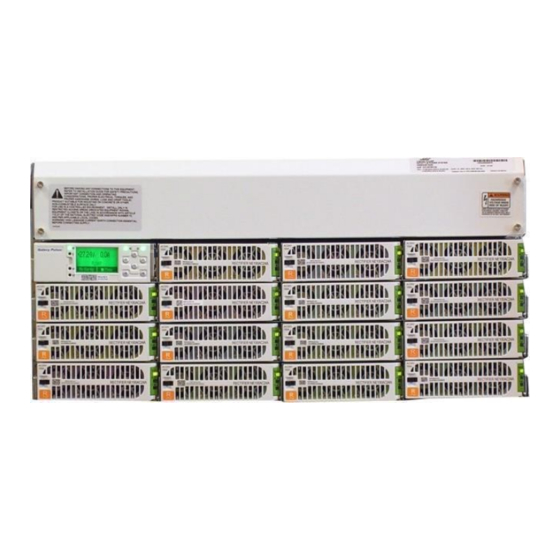
QUICK START GUIDE
Infinity B (NE-B) G240 System -48V, +24V,
+24V/-48V or –48V/+24V
Use a #10 or 1/4" diameter double-hole lug on 5/8"
center (Not provided) to ground the chassis; Torque
connections to 35 in- lbs using 5/16" nut driver
The ac input panel is directly above the top row of
power modules. 1" and 1-1/2" conduit knockouts are
located on the left and right ends of the ac panel.
Each rectifier position is factory configured for
individual 208/220VAC inputs. Individual inputs
require 20A protectors and 10 AWG wires. Two
rectifier positions can be fed from one ac source by
installing the provided jumpers. When using one
input for two rectifiers a 40A protector and 8 AWG
wire is required. Recommend two 1-1/2" conduits
feeding up to 8 rectifiers per conduit; (16) 10 AWG
Page 1
© 2021 ABB. All rights reserved.
•
Shelf Chassis
Ground Options
Rectifiers
Rectifiers
41
42 31 32 21 22 11 12 13 14 23 24 33 34 43
L1
L1 L1 L1 L1 L1 L1 L1 L1 L1 L1 L1 L1 L1 L1
L2
L2 L2 L2 L2 L2 L2 L2 L2 L2 L2 L2 L2 L2 L2
Rectifiers
Rectifiers
44
L1
L2
Advertisement

Related Manuals for ABB Infinity B G240 System -48V


Summary of Contents for ABB Infinity B G240 System -48V
- Page 1 L1 L1 L1 L1 L1 L1 L1 L1 L1 L1 L1 L1 L1 L1 feeding up to 8 rectifiers per conduit; (16) 10 AWG L2 L2 L2 L2 L2 L2 L2 L2 L2 L2 L2 L2 L2 L2 Page 1 © 2021 ABB. All rights reserved.
- Page 2 10 inch lbs. Straps and screws are provided. Attach the 8 AWG AC input wires to the terminal blocks and torque the wire clamps to 10 inch-lbs. Page 2 © 2021 ABB. All rights reserved.
- Page 3 J1 Optional system Interface. See table below. J2 Thermal probes. See back page. J3 Auxiliary Inputs J5 LAN Close on Alarm -48V /+24 V Open on Alarm System reference voltage and alarm output jumpers. Page 3 © 2021 ABB. All rights reserved.
- Page 4 AC Fail (ACF) R4_C AC Fail_C (ACF_C) Rectifier Fail (RFA) R5_C Rectifier Fail_C (RFA_C) Mult. Rectifier Fail (MRFA) Mult. Rectifier Fail_C R6_C (MRFA_C) High Voltage (HV) BK/R R7_C High Voltage_C (HV_C) R/BK Page 4 © 2021 ABB. All rights reserved.
- Page 5 3/8” di- ameter lugs on 1” centers spaced 1.75“ apart. Three 750 MCM Flex lugs can be connected per bus. Bus extensions are provided to land four additional cables back to back. Page 5 © 2021 ABB. All rights reserved.
- Page 6 Configuration > Batteries. Using web pages or EasyView2; Select the Installation Tab to set the Date, Time. Site ID and Site Description. Select the Settings Tab > Battery Management to verify Battery Type and set number of battery strings installed. Page 6 © 2021 ABB. All rights reserved.
- Page 7 54.40 Battery on Discharge Float Alarm -46 to -55V 51.00 50.00 51.00 Very Low Float Voltage Alarm -40 to -51V 46.00 46.00 46.00 Rectifier On Threshold -40 to -51V 44.00 44.00 44.00 Page 7 © 2021 ABB. All rights reserved.
- Page 8 Probes are used to monitor battery temperature and mid-string voltage (ES771 required to monitor voltage). Bolt the Probe under the “–“ terminal connector hardware; NOT under the connecting lug. Temperature monitoring Temperature and voltage monitoring Page 8 © 2021 ABB. All rights reserved.
- Page 9 With regard to and illustrations contained therein. Any reproduction, disclosure purchase orders, the agreed particulars shall prevail. ABB AG does to third parties or utilization of its contents–in whole or in not accept any responsibility whatsoever for potential errors or parts –...