Table of Contents
Advertisement
Quick Links
Coffee Machine
Service
Service Manual
Table of contents
1.
1.1.
1.2.
1.3.
1.4.
1.5
1.6.
1.6.
2.
2.1.
Technical specifications
2.2.
2.3.
Specification for the measurement of the coffee prod-
ucts temperature
2.3.1
3.
3.1.
3.2.
3.3.
4.
4.1.
4.2.
4.3.
4.4.
4.5.
4.6.
4.7
All parts of this document are the property of Saeco International Group.
All rights reserved. This document and all the information herein is provided without liability deriving from any errors or omissions. Furthermore, no part may be reproduced,
used or collected, except where express authorization has been provided in writing or through a contractual agreement.
Published by Saeco International Group
Revision 01 November 2015
Page
Table of contents
4.8.
4.9.
1
1
4.10.
1
1
5.
2
5.1.
3
5.2.
4
5.3
6.
1
6.1.
2
4
7.
7.1.
5
7.2.
7.3.
7.4.
7.5.
1
7.6.
3
7.7.
4
7.8.
7.9.
7.10.
1
7.11.
Gear motor
2
7.12.
2
7.13.
3
4
7.14.
5
7.15.
5
7.16.
Subject to modification
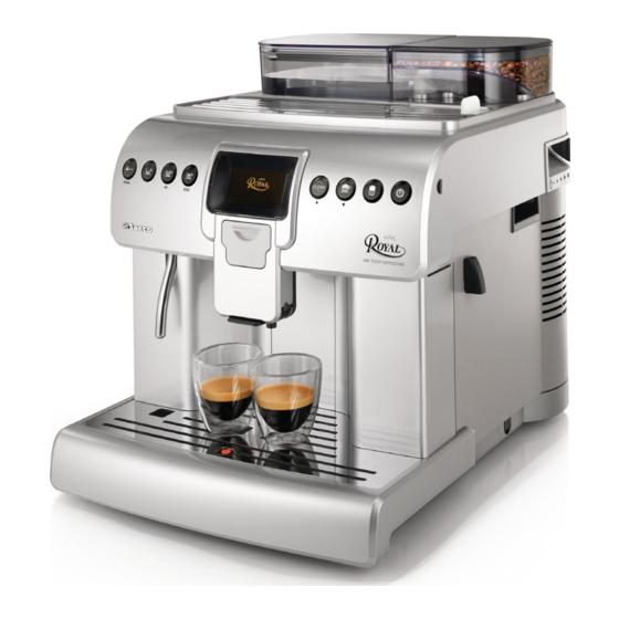
HD 8930
New Royal
Page
6
6
7
1
5
7
1
1
1
2
3
3
3
4
4
4
5
5
6
6
7
7
7
EN 4219 400 013
2011-July-08
Advertisement
Table of Contents

Related Manuals for Philips Saeco New Royal


Summary of Contents for Philips Saeco New Royal
-
Page 1: Table Of Contents
HD 8930 Coffee Machine New Royal Service Service Manual Revision 01 November 2015 Table of contents Page Table of contents Page Introduction 4.8. Water level detection (water tank) 4.9. Descaling request 1.1. Documentation required 1.2. Tools and equipment required 4.10. Water filter 1.3. - Page 2 Table of contents Page 7.17. Display, keypads and control board 7.18. Fitting and removing Oetiker clamps Notes Water circuit diagram Electrical diagram MODIFICATIONS TO SERVICE MANUAL From Rev. To Rev. Chapter Inserted Modified Par. 1.4. Safety warnings 1.5 Service Policy Par.
- Page 3 Saeco International Group Rev. 00 / July 2011 NEW ROYAL...
-
Page 4: Introduction
NEW ROYAL 01 INTRODUCTION 1.1. Documentation required The following documentation is needed for repair procedures: • Instruction booklet for specific model. • Technical documentation for specific model (diagrams, exploded views). 1.2. Tools and equipment required As well as the standard equipment, the following is required: Qty. Description Notes Screwdriver Torx T 8 - T 10 - T 20 Screwdriver Cross-head Pliers for Oetiker clamps CC -A - Vdc tester Digital thermometer Scale limit > 150°C SSC (Saeco Service Center) Programmer (for programming and diagnostics mode) -
Page 5: Service Policy
NEW ROYAL 01 INTRODUCTION Water Flowmeter Two-way solenoid valve Two-way solenoid valve Flowmeter Image 1 Hot water /steam From this point circuit in pressure From this point circuit High temperaure Steam and hot water Steam pipe Water tank Water tank Pump Pump Brewing Unit Brewing Unit Boiler... -
Page 6: External Machine Parts
NEW ROYAL 01 INTRODUCTION 1.6. External machine parts Coffee bean hopper Water tank Cappuccino maker (removable) Hot water dispensing pipe Grille Full tray floating indica- Drip tray Grinding adjust- ment Pre-ground coffee compart- ment Cup heater plate IRDA for SW programation Coffee dose adjustment Brewing unit Main switch 0/I Service hatch Dreg drawer Power cable connector... -
Page 7: Internal Machine Parts
NEW ROYAL 01 INTRODUCTION 1.7. Internal machine parts Coffee boiler Gear motor assembly Steam boiler Relief valve assembly Coffee grinding assembly Doser assembly Ground coffee hop- Power board Solenoid valve assembly Control board Saeco International Group Rev. 00 / July 2011 Page / 04... - Page 8 Saeco International Group Rev. 00 / July 2011 NEW ROYAL...
-
Page 9: Technical Specifications
NEW ROYAL 02 TECHNICAL SPECIFICATIONS 2.1. Technical specifications Power supply and output: 240 V~ 50 Hz 1500 W - 230 V~ 50/60 Hz 1400 W (NTC) variable resistor sensor - transmits the value to the Temperature monitoring: electronic card Safety system: 2 thermostats at 190°C one shot Coffee heat exchanger output: (230 V~) 1300 W for coffee dispensing Stainless steel Steam heat exchanger output: (230 V~) 1300 W for water/steam dispensing Stainless steel Gear motor: 2 rotation directions; power supply 24VC Ulka Type EP5/S GW approx. 13-15 bar with reciprocating Coffee pump piston and thermal switch 120°C 48 W, 230V, 50 Hz, Ulka HF with reciprocating piston 230V, 50 Hz and thermal Steam pump switch 120°C - 22W... -
Page 10: Machine Parameters And Performance
NEW ROYAL 02 TECHNICAL SPECIFICATIONS 2.2. Machine parameters and performance Minimum Default Maximum PRODUCT User pro- Programm. by quantity quantity quantity QUANTITY grammable Production / Service (Puls.) (Puls.) (Puls.) Espresso 130 - 170 * Coffee 200 -280* Long coffee 330 - 440 * American coffee Pre-ground Hot water Continues for 400 pulses * Depends on the language selected by the user RINSE... - Page 11 NEW ROYAL 02 TECHNICAL SPECIFICATIONS DREG DRAWER Description and values 5 sec. Time-out for dreg drawer Yes, after 15 lots of dregs Warning to empty dreg drawer after Empty dreg drawer blocking alarm after 18 lots of dregs (double coffee is the last beverage (19 lots of dregs) dispensed) The dreg drawer must be emptied only when prompted by the machine ensuring Reset dreg counter the machine is switched on and removing...
- Page 12 NEW ROYAL 02 TECHNICAL SPECIFICATIONS 2.3. Specification for the measurement of the coffee products temperature. The temperature is influenced by the flow from the dispenser and stratification of temperatures in the glass. In order to consider these phenomena and to introduce measures that allow comparisons in controlled conditions, below guidelines must be followed: Conditions: a) Water temperature in tank: 23°C (+/-2°C). b) It must be used a plastic cup (see picture N°1). c) It must be used a thermocouple thermometer (e.g. type K - see picture N°2). d) The coffee machine is tested without any change of parameters or calibrations, which may affect the temperature of products, so the measurement of temperature must be done with machine in default factory setting. Procedure: 1. The temperature must be measured in the cup, immediately after dispensing. Cup has to be placed on a non-metal surface using a thermocouple thermometer (Picture 1).
-
Page 13: Specification For The Measurement Of The Milk Products Temperature
NEW ROYAL 02 TECHNICAL SPECIFICATIONS 2.3.1. Specification for the measurement of the Milk products temperature. Milk evaluation To carry out the test, a partially skimmed UHT milk with a percentage of grease between 1.5-1.8% at a refrigerator temperature Trefr. (between 4 to 10°C) must be used. The milk product must be checked on a beaker of 250 ml of capability and with an inner diameter of 70mm, brewing 100gr of product. Parameters to be respected: The parameters to be respected are: milk temperature and height of the cream. Each of these pa- rameters, however, must be evaluated depending on the type of system used for the production of hot milk. - Page 14 NEW ROYAL 02 TECHNICAL SPECIFICATIONS How to measure the milk cream. The temperature (Trefr or Tamb) of the milk doesn’t affect as much the test result on measuring the milk cream; by convection is assumed to always use milk at refrigerator temperature Trefr.. Manual systems (Pannarello) Pour 100cc. of milk at Trefr. in a beaker of 250 ml of capacity and with a inner diameter of 70 mm; with machine in steam mode: 1. Open the steam knob to discharger water circuit for 4 sec, then close the knob. 2. Place the beaker with the frother dipped in milk, open the steam knob to maximum and start the chronometer. 3.
- Page 15 Saeco International Group Rev. 00 / July 2011 NEW ROYAL...
-
Page 16: User Instructions
NEW ROYAL 03 USER INSTRUCTIONS 3.1. Customer and programming menu MENU Pre-ground selection button - MENU 2nd function - Press for 5 seconds to access This button is used to select the possibility to the machine programming menu. dispense the coffee with pre-ground coffee. MENU Espresso dispensing button Coffee button - OK 2nd function - Press to select the heading The button is used to select shown on the display. - Page 17 NEW ROYAL 03 USER INSTRUCTIONS MACHINE MENU Used to customize the machine's operational settings To change the appliance operating settings GENERAL MENU This function permits activating/deactivating audible warnings SOUND To disable buzzers To enable buzzers This function governs activation of the boilers in the appliance for energy saving ECOMODE When the machine is switched on all the boilers (coffee/steam) come on to allow the immediate preparation of all beverages. When the appliance is switched on, only the coffee boiler is activated. The appliance consumes less power but takes longer to dispense milk beverages This function is used to set the time since the last beverage dispensing when the machine will go onto...
-
Page 18: Machine Indications
NEW ROYAL 03 USER INSTRUCTIONS MAINTENANCE This function lets you set all the functions so that machine maintenance is managed better MAINTENANCE This function is used to run the washing cycle for the Brewing Unit UNIT CLEANING This function is used to run the descaling cycle DESCALING This function lets you run the washing cycle for the cappuccino maker used for making beverages CAPPUCCINO MAKER... -
Page 19: Operation, Cleaning And Maintenance
NEW ROYAL 03 USER INSTRUCTIONS 3.3. Operation, cleaning and maintenance Operating the machine Fill water tank Fill the coffee bean hopper Switch on the appliance Press the button to start the appliance Select the desired language Store Heating When the heating phase begins, wait for it to finish Rinse Carry out a rinse cycle for the internal circuits Machine ready The machine is ready to dispense beverages... - Page 20 Saeco International Group Rev. 00 / July 2011 NEW ROYAL...
-
Page 21: Operating Logic
NEW ROYAL 04 OPERATING LOGIC 4.1. Water circuit Saeco International Group Rev. 00 / July 2011 Page / 07... -
Page 22: Frother Unit Valve Assembly
NEW ROYAL 04 OPERATING LOGIC 4.2. Frother unit valve assembly HOT WATER STEAM DRAIN 1 Outlet leading to the cappuccino maker for milk-based products 2 Outlet leading to the steam pipe but which dispenses hot water only 3 Outlet for reducing the internal pipe pressure after dispensing 4 Safety valve protecting the valve assembly... -
Page 23: Relief Valve
NEW ROYAL 04 OPERATING LOGIC 4.4. Relief valve Drain to drip tray Needle Drain Functions: Safety valve: functions as a safety valve by opening towards the drain in the event that the pressure rises above 16-19 bar Filling the circuit: The solenoid valve opens (drain position) and the pump is activated, automatically refilling the circuit by expelling the air in the pipe Unit discharge: before the unit descends it opens briefly, discharging the pressure created to prevent spraying and making the dregs drier Coffee beverage: when a coffee beverage is selected, the pump is charged briefly during the grinding process and... -
Page 24: Coffee Cycle
NEW ROYAL 04 OPERATING LOGIC 4.5. Coffee cycle Main switch ON START STOP Time Coffee grinder Pulses (Dosage) Heating approx. 45 sec. Pump Pump activity (flow meter pulses) depending on the product quantity selected Brewing unit gear motor Status Heating Ready Coffee cycle Notes: * Only with Pre-brewing Status Microswitch Single microswitch gear motor... -
Page 25: Single Microswitch
NEW ROYAL 04 OPERATING LOGIC 4.6. Single microswitch The gear motor is powered by a direct cur- rent motor that engages with the smaller double toothed wheel using a worm screw. The unit is mounted on the axle of the large gear wheel and when a coffee is requested, it moves from the standby position to the dis- pensing position, and then back to the stand- by position again. -
Page 26: Water Level Detection (Water Tank)
NEW ROYAL 04 OPERATING LOGIC 4.8. Water level detection (water tank) “Water low” message (water reserve) Function: The water level is monitored by a capacitative sensor, located one Water tank third of the way up the water tank wall. If the electronics assembly detects, by means of the sensor, that the amount of water in the tank has dropped below the above mentioned level, a water reserve remains available for Sensor the dispensing process underway (this will cover 200 flow meter... -
Page 27: Water Filter
NEW ROYAL 04 OPERATING LOGIC 4.10. Water filter Water filter Function: • Reduced limescale deposits which take longer to form. • Improved water quality. • Improved taste due to the ideal water hardness Life span / descaling performance: • - 10 ° dH • 6 0 litres • 2 months To achieve the best possible operating mode consistency... - Page 28 Saeco International Group Rev. 00 / July 2011 NEW ROYAL...
-
Page 29: Troubleshooting
NEW ROYAL 05 TROUBLESHOOTING 5.1. Test mode SX3 SX4 DX3 DX4 MENU BUTTON MAIN FUNCTION SECONDARY FUNCTION Select ground/pre-ground Menu access (hold down) Espresso Coffee Access to Special Menu Clean cycle Scroll menu up Cappuccino Scroll menu down Latte macchiato Entry to Stand-By To enter Test Mode: - Switch on the machine. - P ress the four function keys in the sequence indicated below (SX3, SX2, SX4, SX1) before the initialization bar is completed. - Page 30 NEW ROYAL 05 TROUBLESHOOTING Description of each page 1 Software 1 Software DF:64 ER:8 Debug B2B RI MV: xx xx.yy.zz f: xx Hz Swiss Pow Off SECTOR TYPE DESCRIPTION FUNCTION Provides information on the memory status. Must be 64 FUNCTION Provides information on the memory status. Must be 8 Debug FUNCTION If selected, enables a debug window in user mode The Swiss function is used to enable or disable the ECO-MODE default setting. If Swiss is enabled, the default for the Eco-Mode is “ON”, if Swiss is disabled the default for the Eco-Mode is “OFF”. FUNCTION Swiss The water circuit emptying function restores the ECOMODE value to the default value. As stated above, the default value depends on the Swiss setting. Indicates whether the machine will go to Stand-By mode when powered up - main electro-mechan- FUNCTION Pow Off ical switch (I/O) on, if this occurs the words “Pow Off” are highlighted. If it is disabled, the machine...
- Page 31 NEW ROYAL 05 TROUBLESHOOTING 2 Brew Unit 2 Brew Unit Work Home Stop m Door m Dreg m BU mA: xxxx m Tray Dreg+ Dreg- SECTOR TYPE DESCRIPTION Work FUNCTION If activated, it causes the gear motor to move the unit into the Work position FUNCTION Home If activated, it causes the gear motor to move the unit into the Home position Stop FUNCTION If activated, it stops the gear motor FUNCTION Dreg+ If activated it increases the maximum value of the dregs set before the alarm is activated FUNCTION If activated it decreases the maximum value of the dregs set before the alarm is activated Dreg- INFO...
- Page 32 NEW ROYAL 05 TROUBLESHOOTING SECTOR TYPE DESCRIPTION INFO m Capp Indicates the status of the presence of the cappuccino maker unit if it is inserted it is on Indicates the status of the presence of the milk valve inside the INFO m Milk cappuccino maker if it is inserted it is on...
-
Page 33: Diagnostics Mode
NEW ROYAL 05 TROUBLESHOOTING 5.2. Diagnostics mode SX3 SX4 DX3 DX4 MENU To enter Diagnostics mode: - Switch on the machine - P ress the four function keys in the sequence indicated below (SX2, SX4, SX1, SX3) before the initialization bar is completed Description of menus in diagnosis mode MENU PRODUCT COUNTERS ERROR COUNTERS WATER COUNTERS HOTWATER FLOWRATE CUP TEMPERATURE 1. - Page 34 NEW ROYAL 05 TROUBLESHOOTING Press buttons DX2 or DX1 to move the cursor onto the desired beverage and press SX3 to enter the sub-menu 1. PRODUCT COUNTERS • ESPRESSO (default 0) • dispensing no. • COFFEE (default 0) • dispensing no. • LONG COFFEE (default 0) • dispensing no. •...
-
Page 35: Error Messages
NEW ROYAL 05 TROUBLESHOOTING 5.3. Error messages Code Brief description Description The coffee grinder is blocked (grinder blades Coffee grinder blocked jammed or sensor not reading properly) Brewing unit blocked in ‘work’ Descent time-out exceeded position Brewing unit blocked in ‘home’ Ascent time-out exceeded position No water in flow meter or flow meter not turning Water circuit blocked (jammed) Frother unit solenoid valve Frother unit solenoid valve short-circuit Doser microswitch blocked Doser microswitch short-circuit Coffee boiler short-circuit... - Page 36 Saeco International Group Rev. 00 / July 2011 NEW ROYAL...
-
Page 37: Servicing And Maintenance
NEW ROYAL 06 SERVICE AND MAINTENANCE 6.1. Repair Flow Proces stap Saeco no. Action Intake Visual inspection (transport damage) take care for pictures Check Type/serialnumber Log all available accessory Diagnosis Check product for consumer complaint (NFF contact consumer) Opening machine Visual inspection check for loosen parts, leaking etc.. - Page 38 NEW ROYAL 06 SERVICE AND MAINTENANCE Noise Is the sound normal Crema Blow on the coffee. Does the crema come back together Is the crema colour correct (Hazelnut) Temperature Is the coffee temperature within spec Grinder Is the grinder noise normal Steam Steam Does the steam work...
- Page 39 Saeco International Group Rev. 00 / July 2011 NEW ROYAL...
-
Page 40: Disassembly
NEW ROYAL 07 DISASSEMBLY 7.1. Outer elements Loosen the screws as illus- trated and remove the grinding adjustment lever handle. Remove the lid and the water tank, coffee Loosen the screw bean and ground coffee container lid, dreg as illustrated and drawer, drip tray, brewing unit, coffee unit remove the grinding support plate, coffee dispenser. adjustment lever. Lift the upper lid and disconnect the Slide out the pin Loosen the screws as electrical and water circuit connections... -
Page 41: Grinder Blades
NEW ROYAL 07 DISASSEMBLY 7.3. Grinder blades Lower grinder (1) and To slide out the upper grinder support turn the nut (A) upper grinder (2). anticlockwise until it is released. Release the upper grinder lid by pressing on the fins as illustrated (A) and remove Loosen the screw as illustrated and slide out the lower the grinder by unhooking the catches as grinder. When re-assembling take care to replace the illustrated (B). -
Page 42: Coffee Grinder Motor
NEW ROYAL 07 DISASSEMBLY 7.4. Coffee grinder motor Release the motor support by Remove the three grind- Remove the balls as illustrated, the lifting the catches as illustrat- ing dampers and the felt springs underneath and lift up the ed and replace the motor. ring. grinding support. -
Page 43: Coffee Boiler And Steam Boiler
NEW ROYAL 07 DISASSEMBLY 7.7. Coffee boiler and steam boiler Loosen the screws as illustrated Loosen the screw as illustrated, remove the boiler support and remove the boiler pin. and disconnect the electrical and water circuit connections. 7.8. Boiler pin Loosen the screws as illustrated and remove Slip off the pin support and loosen the screw as illustrated. the boiler pin cover. -
Page 44: Flow Meter
NEW ROYAL 07 DISASSEMBLY 7.10. Flow meter Remove the boiler support lift the flow meter upwards and disconnect the electrical and water circuit connections. Loosen the screws as illustrated and remove Loosen the screws as illustrated and remove the gear motor assembly. the gear motor cover. The following are located inside the compartment protected by the casing: - E lectric motor (A) with gears (B) and (C) for transmission and... -
Page 45: Relief Valve
NEW ROYAL 07 DISASSEMBLY 7.12. Relief valve To remove the discharge valve (A) as illustrated Loosen the screw under the Disconnect all electrical and water firstly loosen the screws which hold the boiler machine as illustrated. circuit connections. pin cover in place then remove it. 7.13. Solenoid valve assembly Loosen the screws as illustrated and slide out the card sup- port to access the solenoid valve assembly more easily. -
Page 46: Steam Pipe Assembly
NEW ROYAL 07 DISASSEMBLY 7.14. Steam pipe assembly Loosen the screws as illustrated and slide out the card sup- port to access the solenoid valve assembly more easily. Loosen the screws as illustrated and remove the clip. 7.15. Dispenser assembly Loosen the screws as illustrated and slide out the card sup- port to access the solenoid valve assembly more easily. - Page 47 NEW ROYAL 07 DISASSEMBLY 7.17. Display, keypads and control board Loosen the screws on the back of the display assembly as illus- Loosen the screws as illustrated and disconnect the elec- trated. trical connections and remove the display assembly. Loosen the screws shown and slide out the keypads. Loosen the screws as illustrated and disconnect all electrical connections.
- Page 48 NEW ROYAL 07 DISASSEMBLY Control board and display card 7.18. Fitting and removing Oetiker clamps assembly 1) Boiler connection 2) Other connections Use a suitable pair of pliers to remove the Tighten the clamp as illustrated. clamp (as illustrated). Saeco International Group Rev.
- Page 49 Saeco International Group Rev. 00 / July 2011 NEW ROYAL...
- Page 50 NEW ROYAL 08 NOTES Saeco International Group Rev. 00 / July 2011 Page / 01...
- Page 51 Saeco International Group Rev. 00 / July 2011 NEW ROYAL...
- Page 52 NEW ROYAL 09 WATER CIRCUIT DIAGRAM Saeco International Group Rev. 00 / July 2011 Page / 01...
- Page 53 Saeco International Group Rev. 00 / July 2011 NEW ROYAL...
- Page 54 NEW ROYAL 10 WIRING DIAGRAM Saeco International Group Rev. 00 / July 2011 Page / 01...