
Related Manuals for Asus EBE-4U


Summary of Contents for Asus EBE-4U
- Page 1 EBE-4U / EBE-4UG ASUS IPC (Industrial Computer Barebone) User’s Manual EBE-4U EBE-4UG Applicable for products with P/N of 90AE0063* & 90AE00H3*...
- Page 2 Product warranty or service will not be extended if: (1) the product is repaired, modified or altered, unless such repair, modification of alteration is authorized in writing by ASUS; or (2) the serial number of the product is defaced or missing.
-
Page 3: Table Of Contents
Table of contents Notices ......................v Safety information ..................vi About this guide .................... vii System package contents ................viii Chapter 1 System introduction Welcome! ..................1-2 Brief introduction ................1-2 Front panel ..................1-4 Rear panel ..................1-5 Internal components ................. 1-7 Chapter 2 Motherboard information Before you proceed ................ - Page 4 Table of contents 3.3.8 Serial Console Configuration ..........3-8 3.3.9 SATA Configuration ............. 3-9 3.3.10 USB Configuration ............... 3-9 3.3.11 Onboard Devices Configuration .......... 3-9 3.3.12 APM Configuration ............3-10 3.3.13 EzFlash ................3-10 3.3.14 Watchdog Timer ..............3-11 3.3.15 Network Stack Configuration ..........3-11 3.3.16 Miscellaneous ..............
-
Page 5: Notices
Notices ASUS Recycling/Takeback Services ASUS recycling and takeback programs come from our commitment to the highest standards for protecting our environment. We believe in providing solutions for you to be able to responsibly recycle our products, batteries, other components, as well as the packaging materials. -
Page 6: Safety Information
Safety information Electrical safety • To prevent electric shock hazard, disconnect the power cable from the electric outlet before relocating the system. • When adding or removing devices to or from the system, ensure that the power cables for the devices are unplugged before the signal cables are connected. If possible, disconnect all power cables from the existing system before you add a device. -
Page 7: About This Guide
How this guide is organized This guide contains the following parts: Chapter 1: System introduction This chapter gives a general description of ASUS EBE-4U. The chapter lists system features, physical descriptions of the front and rear panels, and an overview of internal components. -
Page 8: System Package Contents
System package contents Check your EBE-4U system package for the following items. If any of the items is damaged or missing, contact your retailer immediately. Item Description ASUS EBE-4U barebone system with • ASUS industrial motherboard • Industrial power supply unit •... - Page 9 Chapter 1 This chapter gives a general description of ASUS EBE-4U. The chapter lists system features, physical descriptions of the front and rear panels, and an overview of internal components. The illustrations in this user manual are for reference only. Actual product...
-
Page 10: Chapter 1 System Introduction
Welcome! Thank you for choosing the ASUS EBE-4U! The ASUS EBE-4U provides cutting-edge performance and uncompromised reliability for industrial use. The system is powered by the ASUS motherboard that supports the 7 Intel Core™ i7 / ® i5 / i3, Pentium... - Page 11 2260 2242 PCI_5 USB56 AAFP COM3 COM4 GPIO_CON SPEAKER LPC_DEBUG USB78 CLRTC F_PANEL CHASSIS Chassis Motherboard (ASUS H110A-IM-AB) Power supply unit Accessory box The tools and components in the table above are not included in the motherboard package. ASUS EBE-4U...
-
Page 12: Front Panel
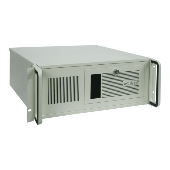
Front panel The front panel includes the optical drive bays, power button, reset button, LED indicators and several I/O ports. Cabinet cover. Use the key to lock or unlock the cabinet cover. Reset button. Press this button to reset the system. Power button. -
Page 13: Rear Panel
(LAN) through a network hub. LAN port LED indications ACT/LINK LED Activity/Link LED Speed LED SPEED LED Status Description Status Description No link 10Mbps connection ORANGE Linked ORANGE 100Mbps connection BLINKING Data activity GREEN 1Gbps connection LAN port ASUS EBE-4U... - Page 14 HDMI port. This port is for a High-Definition Multimedia Interface (HDMI ) connector, ® ® and is HDCP compliant allowing playback of HD DVD, Blu-ray, and other protected content. VGA port. This port is for VGA-compatible devices such as a VGA monitor. Serial ports.
-
Page 15: Internal Components
Front panel cover ASUS motherboard PCI Express 3.0/2.0 x16 slot (x16 mode) 5.25-inch optical drive bays 5 x PCI slots 3.5-inch drive bay PCI Express 2.0 x16 slot (x4 mode) Power supply unit Metal bracket lock CPU socket DIMM slots ASUS EBE-4U... - Page 16 Chapter 1: System introduction...
- Page 17 Chapter 2 This chapter provides details about the motherboard that comes with the system. This chapter includes the motherboard layout, jumper settings, and connector locations.
-
Page 18: Chapter 2 Motherboard Information
Before you proceed Take note of the following precautions before you install motherboard components or change any motherboard settings. CAUTION! • Unplug the power cord from the wall socket before touching any component. • Before handling components, use a grounded wrist strap or touch a safely grounded object or a metal object, such as the power supply case, to avoid damaging them due to static electricity. -
Page 19: Motherboard Layout
BUZZER PCI_2 Intel ® 1085 H110 SATA6G_1 SATA6G_2 PCI_3 SATA6G_3 Super PCIEX16_2 M.2(SOCKET3) PCIE SATA IRST AT_ATX_SEL WDT_EN PCI_4 2280 2260 2242 PCI_5 USB56 COM3 COM4 GPIO_CON AAFP USB78 SPEAKER CLRTC LPC_DEBUG F_PANEL CHASSIS 15 14 13 12 ASUS EBE-4U... - Page 20 Connectors/Jumpers/Slots Page COM RING/+5V/+12V selection (COM1/2_SEL) 2-12 ATX power connectors (24-pin EATXPWR, 4-pin ATX12V) 2-16 CPU and chassis fan headers (4-pin CPU_FAN, 4-pin CHA_FAN) 2-16 Intel LGA1151 CPU socket ® DDR4 U-DIMM slots COM Port headers (10-1 pin COM3 - COM8) 2-17 USB 2.0 headers / connectors (10-1pin USB56, USB78 / USB9, USB10) 2-17...
-
Page 21: Central Processing Unit (Cpu)
Merchandise Authorization (RMA) requests only if the motherboard comes with the cap on the LGA1151 socket. • The product warranty does not cover damage to the socket contacts resulting from incorrect CPU installation/removal, or misplacement/loss/incorrect removal of the PnP cap. ASUS EBE-4U... -
Page 22: Installing The Cpu
2.3.1 Installing the CPU CAUTION! LGA1156 CPU is not compatible with the LGA1151 socket. DO NOT install an LGA1156 CPU on the LGA1151 socket. Chapter 2: Motherboard information... - Page 23 ASUS EBE-4U...
-
Page 24: Cpu Heatsink And Fan Assembly Installation
2.3.2 CPU heatsink and fan assembly installation CAUTION! Apply the Thermal Interface Material to the CPU heatsink and CPU before you install the heatsink and fan if necessary. To install the CPU heatsink and fan assembly Chapter 2: Motherboard information... - Page 25 To uninstall the CPU heatsink and fan assembly ASUS EBE-4U...
-
Page 26: System Memory
System memory This motherboard comes with two Double Data Rate 4 (DDR4) Dual Inline Memory Module (DIMM) sockets. The figure below illustrates the location of the DDR4 DIMM sockets: Channel Sockets Channel A U-DIMM_A1* Channel B U-DIMM_B1* Recommended memory configuration DIMM_A1* DIMM_B1* DIMM_B1*... - Page 27 To remove a DIMM ASUS EBE-4U 2-11...
-
Page 28: Jumpers
Jumpers Clear RTC RAM (2-pin CLRTC) This header allows you to clear the CMOS RTC RAM data of the system setup information such as date, time, and system passwords. CLRTC PIN 1 Connector type HEADER 1x2p, 2.54mm pitch, S/T To erase the RTC RAM: 1. - Page 29 The signal is then generated as a chassis intrusion event. CHASSIS PIN 1 Connector type HEADER 4p, K2, 2.54mm pitch ASUS EBE-4U 2-13...
- Page 30 AT/ATX mode selection (3-pin AT_ATX_SEL) AT_ATX_SEL High Active Low Active (Default) Pins 1-2 (Default) ATX mode AT mode HEADER 1x3p, 2.54mm pitch, S/T Connector type WDT Enable jumper (2-pin WDT_EN) A watchdog timer is an electronic timer that is used to detect and recover from computer malfunctions.
-
Page 31: Connectors
CAUTION: Do not forget to connect the fan cables to the fan headers. Insufficient air flow inside the system may damage the motherboard components. These are not jumpers! Do not place jumper caps on the fan headers! ASUS EBE-4U 2-15... - Page 32 COM Port headers (10-pin COM3 - COM8) These headers are for serial (COM) ports. Connect the serial port cables to these headers, then install the module to a slot opening at the back of the system chassis. COM6 COM5 COM8 COM7 RI1# CTS1#...
- Page 33 Serial Peripheral Interface (SPI), allowing you to securely store keys, digital certificates, passwords and data. A TPM system also enhances network security, protects digital identities, and ensures platform integrity. PIN 1 Header 2x7p, K14, 2.0mm pitch Connector type ASUS EBE-4U 2-17...
- Page 34 M.2 slot (SOCKET 3) This slot allows you to install an M.2 SSD module. M.2(SOCKET3) NOTES: • The M.2 SSD module is purchased separately. • This slot supports M Key and 2242/2260/2280 storage devices. 2-18 Chapter 2: Motherboard information...
- Page 35 ATX power button/soft-off button (2-pin PWR_BTN) This 2-pin header is for the system power button. • Reset button (2-pin RESET) This 2-pin header is for the chassis-mounted reset button for system reboot without turning off the system power. ASUS EBE-4U 2-19...
- Page 36 Speaker header (4-pin SPEAKER) The 4-pin header is for the chassis-mounted system warning speaker. The speaker allows you to hear system beeps and warnings. SPEAKER PIN 1 Connector type HEADER 1x4p, 2.54mm pitch, S/T 10. I C header The I C (Inter-Integrated Circuit) header allows you to connect an I compatible IoT security module.
- Page 37 HEADER 2x5p, K10, 2.0mm pitch IMPORTANT! • Scan the QR code to view the meaning of each debugging code. • Debugging codes are only available for ASUS LPC Debug cards. • Contact your region sales representative for LPC Debug cards ordering. ASUS EBE-4U 2-21...
- Page 38 13. LPT header (26-1 pin LPT) The LPT (Line Printing Terminal) header supports devices such as a printer. LPT is standardized as IEEE 1284, which is the parallel port interface on IBM PC-compatible computers. PIN 1 14. Front Panel Audio header (10-1 pin AAFP) This header is for a chassis-mounted front panel audio I/O module that supports HD Audio standard.
- Page 39 Chapter 3 This chapter provides a detailed guide to navigating and setting up the BIOS.
-
Page 40: Chapter 3 Bios Setup
Always shut down the system properly from the operating system. IMPORTANT: • Visit the ASUS website at www.asus.com to download the latest BIOS file for this motherboard. • The default BIOS settings for this motherboard apply to most working conditions and ensures optimal performance. -
Page 41: Bios Menu Screen
The Main menu provides you an overview of the basic system information, and allows you to set the system date, time, language, and security settings. 3.2.1 System Date [Day MM/DD/YYYY] Allows you to set the system date. 3.2.2 System Time [HH:MM:SS] Allows you to set the system time. ASUS EBE-4U... -
Page 42: Advanced Menu
Advanced menu The Advanced menu items allow you to change the settings for the CPU and other system devices. Be cautious when changing the settings of the Advanced menu items. Incorrect field values can cause the system to malfunction. 3.3.1 PCH-FW Configuration TPM Device Selection This item allows you to select the TPM device. -
Page 43: Graphics Configuration
Primary Display. Configuration options: [Auto] [IGFX] [PEG] [PCI] Internal Graphics [Auto] Keep IGFX enabled base on the setup options. [Disabled] Disables internal graphics. [Enabled] Enables internal graphics. RC6 (Render Standby) Allows you to enable or disable render standby support. Configuration options: [Disabled] [Enabled] ASUS EBE-4U... -
Page 44: Pci Express Configuration
3.3.5 PCI Express Configuration Allows you to select a PEG or PCI graphical device. PCIEX16_2 Slot PCIEX16_2 Slot This item allows you to enable or disable the PCIEX16_2 slot. Configuration options: [Disabled] [Enabled] ASPM This item allows you to control the Active State Power Management on both NB (NorthBridge) side and SB (SouthBridge) side of the DMI Link. -
Page 45: Csm Configuration
The following items appear only when you set Serial Port to [Enabled]. COM1 Control Allows you to select the COM1 mode. Configuration options: [RS232] [RS422] [RS485] Serial Port 2 Configuration Serial Port Allows you to enable or disable the serial port (COM).Configuration options: [Disabled] [Enabled] ASUS EBE-4U... -
Page 46: Serial Console Configuration
The following item appears only when you set Serial Port to [Enabled]. COM2 Control Allows you to select the COM2 mode. Configuration options: [RS232] [RS422] [RS485] Serial Port 3 Configuration Serial Port Allows you to enable or disable the serial port (COM).Configuration options: [Disabled] [Enabled] Serial Port 4 Configuration Serial Port... -
Page 47: Sata Configuration
Intel LAN1 Controller [Enabled] Enables the Intel LAN1 controller. [Disabled] Disables the controller. Intel LAN PXE OPROM This item allows you to enable or disable the PXE Option ROM of the Intel LAN1 controller. Configuration options: [Disabled] [Enabled] ASUS EBE-4U... -
Page 48: Apm Configuration
Intel LAN2 Controller [Enabled] Enables the Intel LAN2 controller. [Disabled] Disables the controller. Intel LAN2 PXE OPROM This item allows you to enable or disable the PXE Option ROM of the Intel LAN2 controller. Configuration options: [Disabled] [Enabled] 3.3.12 APM Configuration ErP Ready Allows you to switch off some power at S5 to get the system ready for ErP requirement. -
Page 49: Watchdog Timer
This item allows you to control the Active State Power Management on SA side of the DMI Link. Configuration options: [Disabled][L1] PCI Express Configuration DMI Link ASPM Control This item allows you to control the Active State Power Management of the DMI Link. Configuration options: [Disabled] [Enabled] ASUS EBE-4U 3-11... -
Page 50: Hardware Monitor Menu
Hardware Monitor menu The items in this menu provide you an overview of system status including temperature, fan speed and voltage, and allow you to configure the smart fan. Smart Fan Mode Allows you to select the smart fan mode. Configuration options: [Disabled] [Normal] [Manual Mode] The following item appears only when you set Smart Fan Mode to [Manual Mode]. - Page 51 Key Management The Key Management item allows you to modify Secure Boot variables and set Key Management page. Platform Key (PK) / Key Exchange Keys / Authorized Signatures / Forbidden Signatures Configuration options: [Details] [Export] [Update] [Delete] ASUS EBE-4U 3-13...
-
Page 52: Boot Menu
Boot menu The Boot menu items allow you to change the system boot options. Boot Configuration CHASSIS INTRUDE Allows you to enable or disable the chassis intrusion detection function. Configuration options: [Disabled] [Enabled] Setup Prompt Timeout Allows you to set the number of seconds to wait for setup activation key. 65535(0xFFFF) means indefinite waiting. - Page 53 Allows you to select the boot mode. Configuration options: [LEGACY] [UEFI] FIXED BOOT ORDER Priorities Boot Option #1~#6 This item allows you to set the system boot order. Configuration options: [Hard Disk] [NVME] [CD/DVD] [SD] [USB Device] [Network] [Disabled] ASUS EBE-4U 3-15...
-
Page 54: Exit Menu
Exit menu The Exit menu items allow you to save or discard your changes to the BIOS items. Save Changes & Exit This option allows you to save your changes and exit the Setup program. When you select this option or if you press <Esc>, a confirmation window appears. Select Yes to save changes and exit. -
Page 55: Appendix
Appendix Notices FCC Compliance Information Responsible Party: Asus Computer International Address: 48720 Kato Rd., Fremont, CA 94538, USA Phone / Fax No: (510)739-3777 / (510)608-4555 This device complies with part 15 of the FCC Rules. Operation is subject to the following two conditions: (1) This device may not cause harmful interference, and (2) this device must accept any interference received, including interference that may cause undesired operation. - Page 56 CAN ICES-003(B)/NMB-003(B) VCCI: Japan Compliance Statement Class B ITE KC: Korea Warning Statement HDMI Compliance Statement The terms HDMI, HDMI High-Definition Multimedia Interface, and the HDMI Logo are trademarks or registered trademarks of HDMI Licensing Administrator, Inc. EBE-4U...
- Page 57 ASUS Recycling/Takeback Services ASUS recycling and takeback programs come from our commitment to the highest standards for protecting our environment. We believe in providing solutions for you to be able to responsibly recycle our products, batteries, other components as well as the packaging materials.
- Page 58 UE è disponibile asus.com/support all’indirizzo: www.asus.com/support Português A ASUSTeK Computer Inc. declara que este Русский Компания ASUS заявляет, что это устройство dispositivo está em conformidade com os requisitos essenciais соответствует основным требованиям и другим e outras disposições relevantes das Diretivas relacionadas. Texto соответствующим...
-
Page 59: Service And Support
Service and Support Visit our multi-language website at https://www.asus.com/support/ Appendix...