
Related Manuals for Samsung SP-A800B(H6HA)


Summary of Contents for Samsung SP-A800B(H6HA)
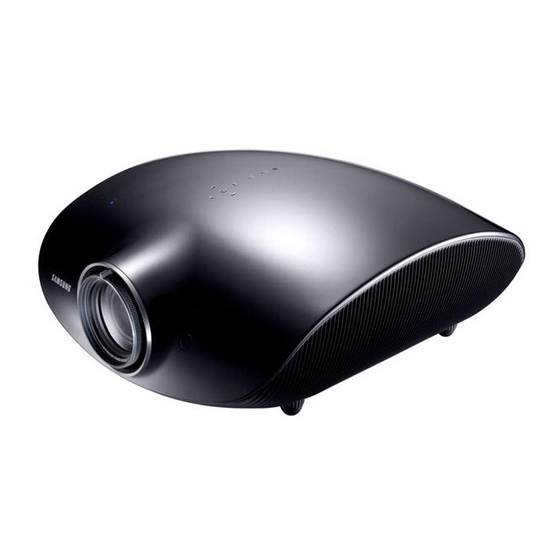
- Page 1 DLP Projector Training Manual SP-A800B(H6HA) Development Lab 7 Development Group 3 Video Display Development Team...
- Page 2 Revision History Rev. 03 Rev. 03 Revision Reviser D ate Remarks Revision Reviser D ate Remarks 1. First D raft 2007.08.24 1. First D raft 2007.08.24 M in-K yung Lee M in-K yung Lee...
- Page 3 Product Background...
- Page 4 Product Overview Product Functions Product Functions W hat i s a Pr oj ect or ? A pr oj ect or pr oj ect s t he s cr een of t he ext er nal devi ce connect ed t o i t , s uch as a PC, DVD, VCR, or cam cor der ont o a m uch l ar ger s cr een.
- Page 5 Product Overview Product Functions Product Functions Advant ages and Di s advant ages of each Pr oj ect or Type I t em CRT Pr oj ect or LCD Pr oj ect or DLP Pr oj ect or Operating The three CRT lenses The image displayed on the The light of the lamp reflects display and magnify the...
- Page 6 High price 3 panels only High price with a resolution of 1080p (4:3) with a resolution of 1080p (4:3) (D igital) (D igital) CRT type (B arco) L CD type (Panasonic) D LP type (Samsung) L COS type (JV C)
- Page 7 Product Overview Product Functions Product Functions CRT Projector...
- Page 8 Product Overview Product Functions Product Functions LCD Projector...
- Page 9 Product Overview Product Functions Product Functions DLP Projector DMD panel Color Wheel Lamp...
- Page 10 Product Overview Product Functions Product Functions DLP (Digital Light Processing) Digital image presentation technology developed by Texas Instruments, USA DMD (Digital Micromirror Device) panel One micromirror represents one pixel. Micromirror size: 13.68 ㎛ x 13.68 ㎛ ...
- Page 11 Product Overview Product Functions Product Functions Mirror: 13.68µm x 13.68µm Yoke Landing Tip Torsion Hinge...
- Page 12 Product Overview Product Functions Product Functions C lick to C lick to Animate!!! Animate!!!
- Page 13 Product Overview Product Functions Product Functions Better Image A better image quality is achieved due to the structural differences of the pixels DLP™ = large ‘active’ area DLP™ = narrow distance between pixels, large effective size of pixels LCD = wide distance between ...
- Page 14 Product Overview Product Functions Product Functions Better Image Quality DLP : A unit pixel has a size of 13.65 ㎛ . A clean screen is presented and no vertical lines are displayed. DLP™ = ‘Seamless’, Filmlike LCD & PDP : Vertical lines are displayed ...
- Page 15 Product Overview Product Functions Product Functions No Convergence CRT, LCOS, psi LCD = 3 Single Panel, no Plasma utilizes RGB panels, or CRTs that will misalignment that will shift over misalign over time time, and due to heat LCD: 3 Elements = 1 Pixel Plasma: 3 Elements = 1 Pixel DLP™: 1 Element = 1 Pixel...
- Page 16 Product Overview Product Functions Product Functions High Contrast DLP™ : Implements a high contrast ratio Comparatively simple optical structure DLP™ : High Contrast LCOS, pSi LCD Comparatively low contrast ratio Comparatively complex optical structure LCD: Low Contrast...
- Page 17 Product Overview Product Functions Product Functions Greater Efficiency DLP 1 Chip: Simple optical structure Reflective structure Enhanced optical efficiency A low power usage lamp can be used Enhanced heat efficiency LCD : Complex optical structure ...
- Page 18 Product Overview Product Functions Product Functions Fast Response DLP™ µs Response Time DMD: The pixel response speed is fast (several us) LCD: The pixel response speed is slow (several tens of ms) Dragging occurs on a fast moving screen. DLP™: Comparatively no dragging occurs.
- Page 19 Product Overview Product Functions Product Functions True Colors Real Reds Real Reds Real Blues Real Blues Can present 35 trillion colors Can present 35 trillion colors...
- Page 20 Product Overview Product Functions Product Functions Am azi ngl y cl ear i m ag e out l i nes !
- Page 21 Product Overview Product Functions Product Functions Implements a clean image using progressive Implements a clean image using progressive scans scans Right Interlaced Image Left Interlaced Image DLP™ Interlaced Always ON Scans every other line 480p 1080i 720p...
- Page 22 Product Overview Product Functions Product Functions Unlike CRTs and PDPs, no Burn-in occurs with DLPs. C lick to C lick to Animate!!! Animate!!!
- Page 23 Product Overview Product Functions Product Functions Technological Superiority of DLP over LCD 1) Narrow distance between pixels. Large active areas. L CD Panel & M agnified Image D L P Panel & M agnified Image 2) Due to the high contrast, the color black is represented outstandingly in dark environments.
- Page 24 Product Overview Product Functions Product Functions 1) Home Theater projector: For creating a Home Theater environment and watching movies 2) D ata projector : For displaying PC documents at presentations and conferences 3) D ifferences when used in a bright environment: - Home Theater projector: A s movies contain various color tones, the representation of dark areas is degraded when this type of projector is used in a bright room.
- Page 25 Product Overview Product Functions Product Functions 1) It is difficult to popularize CRT projectors - D ue to the high price, large size, huge weight (40~90 K g), as well as the difficult installation and adjustment methods, only some home theater ‘fanatics’ are currently using them. 2) A ppearance of digital projectors - A s LCD , D L P, and L COS products, which use micro display technology appear, the price drops, the size and weight decrease, and installation and adjustment methods become simpler.
- Page 26 Product Overview Product Functions Product Functions Item Home Theater Projector Data Projector Item Home Theater Projector Data Projector Aspect 16:9 (DVD and digital broadcasting Aspect 16:9 (DVD and digital broadcasting 4:3 (PC screen specifications) 4:3 (PC screen specifications) Ratio specifications) Ratio specifications) Brightness...
- Page 27 Product Overview...
- Page 28 Product Overview Projector for High-End Home Theaters Projector for High-End Home Theaters Projector for High-End Home Theaters Projector for High-End Home Theaters • I m pl em ent i ng a f ul l HD qual i t y pr oduct wi t h a 1080p DLP panel •...
- Page 29 Product Overview Product Features Product Features Product Features Product Features I t em Rem ar ks 1080p HD product Enhanced clearness Enhanced convenience with a user adjustment mode and User adjustment mode and custom mode custom mode Digital signal processing minimizes image quality HDMI input terminal...
- Page 30 Product Overview Product Functions Product Functions Resolution : 1920*1080 DMD Size : 0.95” Reflective type, DC2 -81QC...
- Page 31 Product Overview Product Structure Product Structure 1. Pr oj ect i on s ys t em ( Lens & t unnel ) 2. I l l um i nat i on s ys t em 3. Col or wheel 4. Fan ( Mai n) 5.
- Page 32 Product Overview Optical Engine Structure Optical Engine Structure Si de Vi ew Fr ont Vi ew Vi ewi ng di r ect i on Pr oj ect i o n l ens ▶ Lam p: Col l ect s whi t e r adi ant beam s f r om t he l i ght s our ce at a poi nt us i ng an el l i pt i c r ef l ect i ng m i r r or .
- Page 33 Product Overview M ajor Specifications M ajor Specifications M ajor Specifications M ajor Specifications Model SP-A800B Model Size 0.95" DMD Panel Size Panel Panel 1920 x 1080 (Progressive) Resolution Resolution Light source Light source LAMP (300W UHP) Power Power Less than 410 W Consumption Consumption Power...
- Page 34 Component Name Code Remarks Installation Guide BP68- 00652B W arranty BP68- 00570B User Manual BP59- 00131A Samsung Electronics Power Cord 3903- 000212 Service Center Cleaning Cloth BN63- 01798A Remote Control BP59- 00130A Battery...
- Page 35 Product Overview Comparative Specifications with Competitors Comparative Specifications with Competitors Comparative Specifications with Competitors Comparative Specifications with Competitors Maker Samsung Sony Optoma Epson Maker Samsung Sony Optoma Epson Des i gn Des i gn Di m ens i ons Di m ens i ons...
- Page 36 Product Overview Control Panel Control Panel Name Name LED indicators LED indicators ① ① Focus ring Focus ring ② ② Lens Lens ③ ③ Lens positioning dial Lens positioning dial ④ ④ Remote control signal Remote control signal ⑤ ⑤ receiver receiver Height adjustment legs...
- Page 37 Product Overview Control Panel Functions Control Panel Functions Name Description Name Description LED indicators LED indicators Displays the operating status of the product. Refer to the LED Indicators. ① ① Focus ring Focus ring Used to adjust the image focus. ②...
- Page 38 Product Overview Ext er nal Ext er nal I nput Li s t I nput Li s t Component1 / Component2 / S- Video / Video / Component1 / Component2 / S- Video / Video / PC /HDMI1 / HDMI2 PC /HDMI1 / HDMI2 Edi t Ext er nal Edi t Ext er nal...
- Page 39 Product Overview Front Floor / Front Ceiling / Rear Floor / Rear Ceiling I ns t al l at i on Front Floor / Front Ceiling / Rear Floor / Rear Ceiling I ns t al l at i on Theater Mode / High luminance Mode Li ght Sour ce Theater Mode / High luminance Mode...
- Page 40 Product Overview LED Indicators LED Indicators ●: On ◐: Blinking ○: Off STANDBY L AM P TEM P Description The power is being supplied normally. If you press the Power button on your remote control or projector to turn it ●...
- Page 41 Circuit Description...
- Page 42 Temp Temp Sensor Sensor Circuit Description Attachment!!! Attachment!!! Overall Block Diagram Overall Block Diagram CV BS Signal SP-A800B BlockDiagram Power K eypad K eypad...
- Page 43 Circuit Description Digital Board Block Diagram Digital Board Block Diagram...
- Page 44 Circuit Description Formatter Board Block Diagram Formatter Board Block Diagram...
- Page 45 Circuit Description DMD Board Block Diagram DMD Board Block Diagram...
- Page 46 Circuit Description Block Diagrams Block Diagrams Di gi t al Boar d: Digital Board: Receives various video signals and control signals CV BS and controls the formatter board, DMD board, cooling fans, and SMPS board, etc., and processes video signals and transmits them to the formatter board. For m at t er Boar d : Processes the video signals received from the digital board and operates the DMD panel through the DMD board.
- Page 47 Circuit Description Attachment!!! Attachment!!! Schematic Diagrams Schematic Diagrams CV BS SP-A800B ȸ·Îµµ...
- Page 48 Circuit Description Attachment!!! Attachment!!! Wiring Diagrams Wiring Diagrams SP-A800B °á¼±µµ...
- Page 49 Circuit Description Digital Board Digital Board 1. MST3386: 2- por t HDMI Recei ver : Recei ves HDMI s i gnal s , conver t s t hem t o di gi t al vi deo s i gnal s , and t r ans m i t s t hem t o t he Scal er . 2.
- Page 50 Circuit Description Formatter Board Formatter Board 1. DDP3021 ( DMD Dr i ver ) : Tr ans m i t s var i ous cont r ol s i gnal s f or oper at i ng t he DMD panel and t he s i gnal s r ecei ved f r om t he TMDS r ecei ver t o t he DMD panel .
- Page 51 Circuit Description DMD Board DMD Board 1. DMD Panel: Displays the image signals received from DDP3021 as an image 2. DAD1000: Supplies the various power supplies for operating the DMD panel.
- Page 52 Disassembly and Assembly...
- Page 53 Disassembly and Assembly Preparations Preparations W arning: As this projector has parts that are sensitive to static electricity, be careful when handling them. Caution: Turn the projector off before beginning the disassembly. Disassemble the projector carefully as directed in the following procedures. W hen disassembling the projector, do not use any metal tools except for the provided jig.
- Page 54 Disassembly and Assembly – Normal Disassembly Removing the Lamp Removing the Lamp ① ② ③ ④ ⑤ ① Remove the projection lens cover by pressing the left and right hooks on the cover. ② Remove the screw (1) holding the lamp replacement cover in place at the bottom left of the back of the product.
- Page 55 Disassembly and Assembly – Normal Disassembly Removing the Top Cover Removing the Top Cover ① ② ③ ④ ① Lower the height of the projection lens by turning the knob at the bottom of the front of the product. ② Remove the two (2) screws on the left and right at the back of the product. ③...
- Page 56 Disassembly and Assembly – Normal Disassembly Removing the Digital Board - 1 Removing the Digital Board - 1 ① ② ③ ④ ① Unfasten the hooks placed on the left and right by moving them left and right and lifting the top cover of the product.
- Page 57 Disassembly and Assembly – Normal Disassembly Removing the Digital Board -2 Removing the Digital Board -2 ① ② ③ ④ ① Remove the cables connected to the SMPS and unfasten the screw of the GND. ② Remove the digital board located at the back of the product by lifting it slightly. ③...
- Page 58 Disassembly and Assembly – Normal Disassembly Removing the Digital Board -3 Removing the Digital Board -3 ① ② ③ ① Remove the four (4) screws holding the digital board in place at the back of the rear panel. ② Remove the five (5) screws holding the digital board and the shield case in place. ③...
- Page 59 Disassembly and Assembly – Normal Disassembly Removing the LED Board Removing the LED Board ① Remove the LED board assembly from the SMPS shield by turning it clockwise.
- Page 60 Disassembly and Assembly – Normal Disassembly Removing the SMPS Removing the SMPS ① ② ③ ④ ① Remove the two (2) screws holding the product in place. ② Remove the two (2) SMPS power output cables. ③ Remove the four (4) screws holding the SMPS and product in place. ④...
- Page 61 Disassembly and Assembly – Normal Disassembly Removing the DVI Cable / Light Effect Removing the DVI Cable / Light Effect ① ② ① Remove the DVI cable located at the bottom of the product. ② Remove the two (2) screws at the left and right of the light effect. Take care with the cable holder.
- Page 62 Disassembly and Assembly – Normal Disassembly Removing the Ballast Removing the Ballast ③ ② ① ④ ① Remove the three (3) screws on the ballast cover. ② Remove the ballast cover by holding the top of the cover and first lifting and tilting it to the right.
- Page 63 Disassembly and Assembly – Normal Disassembly Removing the Cooling Fan Removing the Cooling Fan ② ③ ① ③ ③ ④ ④ ① Remove the three (3) screws holding the cooling fan structure in place. ② Remove the structure by holding and lifting it with hand. ③...
- Page 64 Disassembly and Assembly – Precision Disassembly Removing the Color Wheel Removing the Color Wheel W arning: The following precision disassembly procedures should be processed in a clean room or comparable facility as the product performance may be degraded or an abnormal symptom may occur on the screen if any foreign material enters the optical engine while disassembling the product.
- Page 65 Disassembly and Assembly – Precision Disassembly Removing the Optical Engine Removing the Optical Engine ① ② ③ ④ ① Pull and remove the hook of the structure covering the projection lens. ② Remove the knob through the bottom hole of the projection lens first. ③...
- Page 66 Disassembly and Assembly – Precision Disassembly Removing the Formatter Board – 1 Removing the Formatter Board – 1 ① ① Remove the two (2) screws holding the formatter board in place and remove the formatter board from the DMD board. - You should pay careful attention during all the disassembly steps as the bottom of the optical engine is not flat.
- Page 67 Disassembly and Assembly – Precision Disassembly Removing the Formatter Board – 2 Removing the Formatter Board – 2 ① ② ① Remove the two (2) hexagonal screws. ② Remove the seven (7) screws holding the board in place and remove the formatter board from the shield case.
- Page 68 Disassembly and Assembly – Precision Disassembly Removing the DMD Board - 1 Removing the DMD Board - 1 During the disassembly procedures, take care that the DMD panel is not stained by foreign material and that you do not touch the panel. ①...
- Page 69 Disassembly and Assembly – Precision Disassembly Removing the DMD Board - 2 Removing the DMD Board - 2 During the disassembly procedures, take care that the DMD panel is not stained by foreign material and that you do not touch the panel. ①...
- Page 70 Disassembly and Assembly Assembly Assembly ★ The assembly is in the reverse order of the disassembly.
- Page 71 Troubleshooting and Adjustments...
- Page 72 Troubleshooting and Adjustment Actions to Take according to LED Indications - 1 Actions to Take according to LED Indications - 1 STANDB L AM P TEM P Description The cooling system inside the projector including the cooling fan is not operating normally. See Action 1 ◐...
- Page 73 Troubleshooting and Adjustment Actions to Take according to LED Indications - 2 Actions to Take according to LED Indications - 2 A ction Status D escription Disconnect the power cord and connect it again. Then run your projector. If the The cooling system inside the projector including the Action 1 same symptom persists, contact your local product distributor or service center.
- Page 74 Troubleshooting and Adjustment Attachment!!! Attachment!!! Troubleshooting – When the Stand-by LED Does Not Turn On Troubleshooting – When the Stand-by LED Does Not Turn On ② ① ③ Is the power cable connected correctly? Connect it correctly. ① Is the SMPS connected correctly? Connect it correctly.
- Page 75 Troubleshooting and Adjustment Attachment!!! Attachment!!! Troubleshooting - When the Power Does Not Turn On Troubleshooting - When the Power Does Not Turn On ① ② Is the power cable connected correctly? Connect it correctly. ① Is the SMPS connected correctly? Connect it correctly.
- Page 76 Troubleshooting and Adjustment Attachment!!! Attachment!!! Troubleshooting 1. The Stand-by and TEMP LEDs Blink Troubleshooting 1. The Stand-by and TEMP LEDs Blink ① ② ③ Is the fan rotating? ① Is the operating voltage of the fan greater than 8V? (Pin 5 of CN1300 and pin 5 of CN1302) Replace the fan.
- Page 77 Troubleshooting and Adjustment Attachment!!! Attachment!!! Troubleshooting 2. The LAMP and TEMP LEDs Blink) Troubleshooting 2. The LAMP and TEMP LEDs Blink) ① Is the lamp replacement cover closed Close the cover correctly. correctly? Is the sensing switch operating normally? Replace the switch. (A short- circuit occurs when the switch is pressed.) (The circuit is open when the switch is in the middle position.)
- Page 78 Troubleshooting and Adjustment Attachment!!! Attachment!!! Troubleshooting 3. The TEMP LED Blinks Troubleshooting 3. The TEMP LED Blinks ① Is the temperature detector operating normally? Replace the temperature detector. (Remove the temperature detector and leave it at room temperature. Check whether a short- circuit has occurred.) ①...
- Page 79 Troubleshooting and Adjustment Attachment!!! Attachment!!! Troubleshooting 4. The Stand-by LED Is Turned On and the LAMP and TEMP Troubleshooting 4. The Stand-by LED Is Turned On and the LAMP and TEMP LEDs Blink LEDs Blink ① ① Is the color wheel rotating? ①...
- Page 80 Troubleshooting and Adjustment Troubleshooting 5. The Stand-by, LAMP, and TEMP LEDs Blink - 1 Troubleshooting 5. The Stand-by, LAMP, and TEMP LEDs Blink - 1 ⑤ ③ ② ④ ① ① Check the lamp. Replace the lamp. Does the lamp have any problem? (Refer to the Lamp Error.) ①...
- Page 81 Troubleshooting and Adjustment Attachment!!! Attachment!!! Troubleshooting 5. The Stand-by, LAMP, and TEMP LEDs Blink - 2 Troubleshooting 5. The Stand-by, LAMP, and TEMP LEDs Blink - 2 ④ Is power supplied to the ballast board normally? Replace the SMPS. Be careful of high voltage: 380V ⑤...
- Page 82 Troubleshooting and Adjustment Attachment!!! Attachment!!! Troubleshooting – When a Blank Screen Is Displayed Troubleshooting – When a Blank Screen Is Displayed Check the video output of the digital Replace the digital board. board. Check the connections between the DMD Connect the connections correctly. board and the formatter board.
- Page 83 Troubleshooting and Adjustment Troubleshooting – When an Input Screen Error Occurs Troubleshooting – When an Input Screen Error Occurs Check the OSD screen. Is there an input screen with no screen Does an error occur? error?. Replace the digital board. Check the test pattern of the DDP in Factory mode.
- Page 84 Troubleshooting and Adjustment Product Installation Product Installation 1. Pr oj ect or I ns t al l at i on .Install the projector so that the projected image is perpendicular to the screen. - Adjust the focus of the lens so that the center of the projected image is at the center of the screen. - If not installed perpendicular to the screen, the projected image may not be shown as a rectangle.
- Page 85 Troubleshooting and Adjustment Product Installation - 2 Product Installation - 2 2. Adj us t i ng t he zoom i ng and f ocus - .You can resize the projected image within the zoom range by rotating the zoom handle. - Rotate the focus ring until the image on the screen is clear.
- Page 86 Troubleshooting and Adjustment Screen Size and Projection Distance Screen Size and Projection Distance Screen Size W idth (X : mm) Height (Y : mm) Maximum Minimum Offset Screen Size W idth (X : mm) Height (Y : mm) Maximum Minimum Offset (mm) (mm)
- Page 87 Troubleshooting and Adjustment Screen Size and Projection Distance Screen Size and Projection Distance Screen Size (mm) Screen Size (mm) W idth (X : mm) W idth (X : mm) Height (Y : mm) Height (Y : mm) Maximum Maximum Minimum Minimum Offset (Y’...
- Page 88 Troubleshooting and Adjustment Adjustments When Replacing a Board Adjustments When Replacing a Board 1. W hen r epl aci ng t he di gi t al boar d - Before replacing: Enter or run Factory Mode - Service - EEPROM Copy - Digital to Formatter to copy the white balance data to the formatter board, and then replace the digital board.
- Page 89 Troubleshooting and Adjustment Entering the Factory Mode and the Initial Screen Entering the Factory Mode and the Initial Screen 1. Ent er i ng Fact or y Mode ▶ W hen using the factory remote control for the projector provided : Press the factory button within 3 seconds of pressing the Info button.
- Page 90 Troubleshooting and Adjustment Factory Mode _ Service - 1 Factory Mode _ Service - 1 1. Service User Reset DB Deep DDC W rite Enable EEPROM Reset DB Middle Checksum W B Reset Select DB Light DMD ARM App.
- Page 91 Troubleshooting and Adjustment Factory Mode _ Service - 2 Factory Mode _ Service - 2 1. Us er Res et - This is the same function as the [Reset] function in the user menu and resets the items in the user menu to the factory defaults.
- Page 92 Troubleshooting and Adjustment Factory Mode _ Service - 3 Factory Mode _ Service - 3 7. Col or W heel I ndex Del ay - Compensates the reference point of the rotating color wheel. If it is distorted, color is distorted for all input signals.
- Page 93 Troubleshooting and Adjustment Factory Mode _ Service - 4 Factory Mode _ Service - 4 11. DB Deep - Adjusts the position of the DB (Dynamic Black). Adjusts the “ Deep” position in the user menu. - Dynamic Black is a function that allows a dynamic screen to be displayed by adjusting the moving iris inside the projection lens.
- Page 94 Troubleshooting and Adjustment Factory Mode _ Service - 5 Factory Mode _ Service - 5 19. Pr ot ect i on Er r or - Displays the logs of the errors that occurred while the product operated. - Fan1, Fan2, TEMP (Temperature), COVER (Lamp replacement cover), Lamp (Lamp lifetime, etc.), Color W heel, DDP - Fan2 is the reserved item.
- Page 95 S/W Code Update DDC Download...
- Page 96 Installing Flash Downloader_v3.0 Attachment!!! Attachment!!! Preparations Preparations A computer used for downloading A DLP Projector An RS232 cable (Both ends should be female. Pins 2 and 3 must be twisted.) setup.exe The Flash Downloader_v3.0 program...
- Page 97 Installing Flash Downloader_v3.0 Program Installation – 1 Program Installation – 1 Save the Flash Downloader_v0.3 program and run the Setup.exe file. Follow the steps below. Click Next. Select the installation folder and click Next. Click Next.
- Page 98 Installing Flash Downloader_v3.0 Program Installation – 2 Program Installation – 2 Click Next. Click Install. The program is being installed.
- Page 99 Installing Flash Downloader_v3.0 Program Installation – 3 Program Installation – 3 Click Next. The program installation is completed. Click Finish.
- Page 100 Software Code Update Update Sequence - 1 Update Sequence - 1 Caution: Make sure to begin updating after the power cord is disconnected. 1. Save the software code file to update. 2. Run Flash Downloader_v3.0. 3. Set the Flash Size to 1MB (M32C). 4.
- Page 101 Software Code Update Update Sequence - 2 Update Sequence - 2 6. Connect your computer and product using the RS- 232C cable, and connect the power cord to your product and turn it on. (Enter Download Mode… - > Ready is displayed sequentially.) 7.
- Page 102 Software Code Update Update Sequence - 3 Update Sequence - 3 8. The code update is completed. 9. Disconnect the power cord from the product. Then connect it again after one (1) second, turn the product on. 10. Enter Factory mode and check whether the code has been updated correctly by checking the software code version. ※...
- Page 103 DDC (EDID) Input DDC Download DDC Download 1. Turn on the product, enter Factory mode, and set DDC W rite Enable to ON. 2. Run the W inDDC program, and set “ Station” to “ W rite Station” by selecting the Sys Config at the top of the Environment Setup window.
- Page 104 Reference Misconceptions Regarding Connecting to Other Products - Misconceptions Regarding Connecting to Other Products - ① ① Problem D escription This may occur in a Brown tube, PDP or LCD TV. If a still image is displayed continuously, traces and afterimages such as spots remain because of the physical characteristics of this kind of panel.
- Page 105 Reference Misconceptions Regarding Connecting to Other Products - ② Misconceptions Regarding Connecting to Other Products - ② W hen connected to HD or SD digital broadcasts, this product cannot display images with a resolution greater than its display device. W hen receiving digital Therefore, even though it is possible to view digital broadcasts, the broadcasts images may be distorted due the converted resolution.