Table of Contents
Advertisement
Quick Links
❍ SECTION 1.GENERAL
• SERVICING PRECAUTIONS . . . . . . . . . . . . . . . . . . . . . . . . . . . . . . . . . . . . . . . . . . . . . . . 1-2
• ESD PRECAUTIONS . . . . . . . . . . . . . . . . . . . . . . . . . . . . . . . . . . . . . . . . . . . . . . . . . . . . . 1-4
• SPECIFICATIONS . . . . . . . . . . . . . . . . . . . . . . . . . . . . . . . . . . . . . . . . . . . . . . . . . . . . . . . .1-5
❍ SECTION 2. AUDIO PART
• AUDIO TROUBLESHOOTING GUIDE . . . . . . . . . . . . . . . . . . . . . . . . . . . . . . . . . . . . . . . . . 2-1
• BLOCK DIAGRAM . . . . . . . . . . . . . . . . . . . . . . . . . . . . . . . . . . . . . . . . . . . . . . . . . . . . . . . . 2-5
• SCHEMATIC DIAGRAMS . . . . . . . . . . . . . . . . . . . . . . . . . . . . . . . . . . . . . . . . . . . . . . . . . . 2-7
• WIRING DIAGRAM . . . . . . . . . . . . . . . . . . . . . . . . . . . . . . . . . . . . . . . . . . . . . . . . . . . . . . 2-17
• PRINTED CIRCUIT DIARGAMS . . . . . . . . . . . . . . . . . . . . . . . . . . . . . . . . . . . . . . . . . . . . 2-19
❍ SECTION 3.DVD PART TROUBLESHOOTING GUIDE
• ELECTRICAL TROUBLESHOOTING GUIDE . . . . . . . . . . . . . . . . . . . . . . . . . . . . . . . . . . . .3-1
• DVD PART SCHEMATIC DIAGRAMS . . . . . . . . . . . . . . . . . . . . . . . . . . . . . . . . . . . . . . . . . .3-7
• PRINTED CIRCUIT DIAGRAM . . . . . . . . . . . . . . . . . . . . . . . . . . . . . . . . . . . . . . . . . . . . . .3-11
❍ SECTION 4. EXPLODED VIEWS . . . . . . . . . . . . . . . . . . . . . . . . . . . . . . . . . . .4-1
❍ SECTION 5. SPEAKER PART . . . . . . . . . . . . . . . . . . . . . . . . . . . . . . . . . . . . .5-1
❍ SECTION 6. REPLACEMENT PARTS LIST . . . . . . . . . . . . . . . . . . . . . . . . . . .6-1
[CONTENTS]
- 1-1 -
Advertisement
Table of Contents

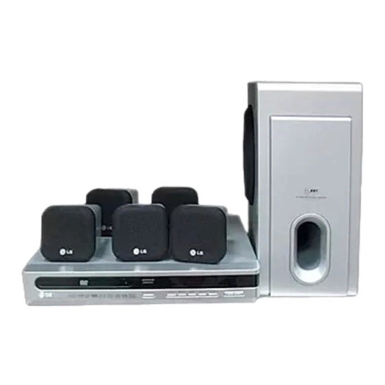
Related Manuals for LG LH-T6340D


Summary of Contents for LG LH-T6340D
- Page 1 [CONTENTS] ❍ SECTION 1.GENERAL • SERVICING PRECAUTIONS ..........1-2 •...
-
Page 2: Section 1. General
SECTION 1. GENERAL ❏ SERVICING PRECAUTIONS NOTES REGARDING HANDLING OF THE PICK-UP 1. Notes for transport and storage 1) The pick-up should always be left in its conductive bag until immediately prior to use. 2) The pick-up should never be subjected to external pressure or impact. Storage in conductive bag Drop impact 2. -
Page 3: Notes Regarding Compact Disc Player Repairs
NOTES REGARDING COMPACT DISC PLAYER REPAIRS 1. Preparations 1) Compact disc players incorporate a great many ICs as well as the pick-up (laser diode). These components are sensitive to, and easily affected by, static electricity. If such static electricity is high voltage, components can be damaged, and for that reason components should be handled with care. -
Page 4: Esd Precautions
❏ ESD PRECAUTIONS Electrostatically Sensitive Devices (ESD) Some semiconductor (solid state) devices can be damaged easily by static electricity. Such components commonly are called Electrostatically Sensitive Devices (ESD). Examples of typical ESD devices are integrated circuits and some field-effect transistors and semiconductor chip components. The following techniques should be used to help reduce the incidence of component damage caused by static electricity. - Page 5 - 1-6 -...
-
Page 6: Section 2. Audio Part
SECTION 2. AUDIO PART ❏ AUDIO TROUBLESHOOTING GUIDE 1. POWER SUPPLY CIRCUIT - 2-1 -... - Page 7 2. FRONT CIRCUIT (1/2) - 2-2 -...
- Page 8 3. FRONT CIRCUIT (2/2) - 2-3 -...
- Page 9 MEMO - 2-4 -...
-
Page 10: Section 3. Dvd Part
SECTION 3. DVD PART TROUBLESHOOTING GUIDE 1. Test & debug flow Check the Tray control IO pins on ES6698FD. - 3-1 -... - Page 11 - 3-2 -...
- Page 12 - 3-3 -...
- Page 13 - 3-4 -...
- Page 14 - 3-5 -...
- Page 15 - 3-6 -...
-
Page 16: Section 5. Speaker Section
SECTION 5. SPEAKER SECTION ❏ MODEL : LHS-T6340T - 5-1 -... - Page 17 ❏ MODEL : LHS-T6340W - 5-2 -...
-
Page 18: Block Diagram
❏ BLOCK DIAGRAM... -
Page 19: Schematic Diagrams
❏ SCHEMATIC DIAGRAMS • POWER SCHEMATIC DIAGRAM... - Page 20 • MICOM SCHEMATIC DIAGRAM 2-10...
- Page 21 • FRONT SCHEMATIC DIAGRAM 2-11 2-12...
- Page 22 • DSP& SCHEMATIC DIAGRAM 2-13 2-14...
- Page 23 • SMPS-NARROW&WIDE SCHEMATIC DIAGRAM 2-15 2-16...
-
Page 24: Wiring Diagram
❏ WIRING DIAGRAM 2-17 2-18... -
Page 25: Printed Circuit Board Diagrams
❏ PRINTED CIRCUIT BOARD DIAGRAMS • MAIN/DVD P.C. BOARD DIAGRAM (BOTTOM) 2-19 2-20... - Page 26 • MAIN/DVD P.C. BOARD DIAGRAM (TOP) 2-21 2-22...
- Page 27 • FRONT P.C. BOARD (BOTTOM) 2-23 2-24...
- Page 28 • FRONT P.C. BOARD (TOP) 2-25 2-26...
- Page 29 • SMPS P.C. BOARD 2-27 2-28...
- Page 30 ❏ DVD SCHEMATIC DIAGRAMS • DVD MPEG & DSP SCHEMATIC DIAGRAM ES6698FD...
- Page 31 • DVD RF SCHEMATIC DIAGRAM 3-10...
-
Page 32: Section 4. Exploded Views
SECTION 4. EXPLODED VIEWS ❏ CABINET AND MAIN FRAME SECTION... - Page 33 • DECK MECHANISM EXPLODED VIEW...