
Related Manuals for ABB HART FEP300


Summary of Contents for ABB HART FEP300
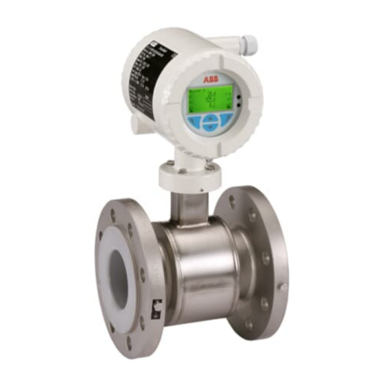
- Page 1 CI/FEP300/FEH300-EN ProcessMaster / HygienicMaster Commissioning Instruction Electromagnetic Flowmeter FEP300/FEH300...
- Page 3 Tel.: +49 551 905-534 Fax: +49 551 905-555 CCC-support.deapr@de.abb.com © Copyright 2008 by ABB Automation Products GmbH Subject to change without notice This document is protected by copyright. It assists the user with the safe and efficient operation of the device.
-
Page 4: Table Of Contents
Contents Safety ..................................4 General Safety Information ..........................4 Symbols and warnings ...........................4 Intended use..............................5 Improper use ..............................5 Technical limit values .............................5 Allowed Fluids ..............................6 Operator liability .............................6 Personnel qualification ...........................6 Transport safety information ..........................6 1.10 Installation safety information.........................7 1.11 Electrical installation safety information ......................7 1.12 Operating safety information ..........................7 Transport................................8... - Page 5 Contents 3.5.6 Ground for devices with hard rubber lining ...................19 3.5.7 Ground for devices with protective plates .....................19 3.5.8 Ground with conductive PTFE grounding plate ..................19 Preparing and routing the signal and magnet coil cable ................20 3.6.1 Protection class IP 68 ...........................22 Connecting the transmitter ...........................24 3.7.1 Connecting the supply power........................24...
-
Page 6: Safety
Safety Safety General Safety Information The “Safety” chapter provides an overview of the safety aspects to be observed for the operation of the device. The device is built based on state-of-the-art technology and is operationally safe. It was tested and left the factory in a proper state. The requirements in the manual as well as the documentation and certificates must be observed and followed in order to maintain this state for the period of operation. -
Page 7: Intended Use
Safety Intended use This device is intended for the following uses: • To transmit fluid, pulpy or pasty substances with electrical conductivity. To measure the flowrate of the operating volume or mass flow units (at constant pressure / • temperature), if a mass engeineering unit is selected. The following items are included in the intended use: •... -
Page 8: Allowed Fluids
Before the use of corrosive and abrasive measuring fluid, the operator must clarify the resistance of all parts that come into contact with the fluid to be measured. ABB will gladly support you with the selection, however, cannot accept any liability. -
Page 9: 1.10 Installation Safety Information
The power supply and the electrical circuit for the coils of the sensor are dangerous and pose a contact risk. The coils and signal circuit can be connected with ABB sensors only. Use the supplied cable. Only electrical circuits that do not pose a contact risk can be connected to the remaining signal inputs and outputs. -
Page 10: Transport
Transport Transport Inspection Check the devices for possible damage that may have occurred during transport. Damages in transit must be recorded on the transport documents. All claims for damages must be claimed without delay against the shipper and before the installation. Transport of flanged units smaller than DN 450 Warning –... -
Page 11: Installation
Installation Installation General information on installation The following points must be observed for the installation: • The flow direction must correspond to the identification if present. • The maximum torque for all flange connections must be complied with. • The devices must be installed without mechanical tension (torsion, bending). •... -
Page 12: Mounting The Measuring Tube
Installation 3.1.2 Mounting the measuring tube The device can be installed at any location in a pipeline under consideration of the installation conditions. Notice - Potential damage to device! Use of graphite with the flange or process connection gaskets is prohibited. In some instances, an electrically conductive coating may form on the inside of the measuring tube. -
Page 13: Torque Information
Installation Torque information 3.2.1 Flanged units ProcessMaster and HygienicMaster Meter size DN Nominal Max. tightening Screws pressure torque Inch 4 x M12 CL 150 4 x M12 3 ... 10 1/10 ... 3/8“ CL 300 4 x M12 4 x M12 1/2“... - Page 14 Installation Meter size DN Nominal Max. tightening Screws pressure torque Inch 12 x M20 12 x M24 12 x M27 10“ 12 x M30 CL 150 12 x M24 CL 300 16 x M27 12 x M20 12 x M24 16 x M27 12“...
-
Page 15: Wafer Type Unit (Hygienicmaster)
Installation 3.2.2 Wafer type unit (HygienicMaster) Meter size DN Nominal Max. tightening Screws pressure torque Inch 4 x M12 3 ... 8 1/10 ... 5/16“ CL 150 4 x M12 upon request CL 300 4 x M12 upon request 4 x M12 3/8“... -
Page 16: Information On 3A Conformity
Installation Information on 3A conformity The device may not be installed vertically with the terminal box or transmitter housing pointing downward. Fig. 5 The "bracket mounting" option no longer applies. Fig. 6 1 Bracket Please ensure that the leakage hole of the process connection is located at the deepest point of the installed device. -
Page 17: Installation Requirements
Installation Change from one to two columns Installation Requirements 3.4.3 Vertical connections • Vertical installation for measurement of abrasive fluids, flow The device measures the flowrate in both directions. The factory preferably from below to above. default is forward flow, as shown inFig. 8. Fig. -
Page 18: Installation In The Vicinity Of Pumps
Installation 3.4.7 Installation in the vicinity of pumps 3.4.9 Installation in pipelines with larger nominal diameters • For flowmeter primaries which are to be installed in the vicinity of pumps or other vibration generating equipment, the utilization of Determine the resulting pressure loss when using reduction pieces mechanical snubbers is advantageous. -
Page 19: Ground
Installation Ground 3.5.1 General information on ground connections Observe the following items when grounding the device: • For plastic pipes or pipes with insulating lining, the ground is provided by the grounding plate or grounding electrodes. • When stray potentials are present, install a grounding plate at the front and back of the flowmeter. -
Page 20: Metal Pipe With Loose Flanges
Installation 3.5.3 Metal pipe with loose flanges 1. Solder the threaded nuts M6 (1) to the pipeline and connect the ground as shown in the illustration. 2. Use a copper wire (at least 2.5 mm² (14 AWG)) to establish the ground connection between the sensor (2) and an appropriate grounding point. -
Page 21: Sensor Type Hygienicmaster
Installation 3.5.5 Sensor type HygienicMaster Ground the stainless steel model as shown in the figure. The measuring fluid is grounded via the adapter (1) and an additional ground is not required. Fig. 22 3.5.6 Ground for devices with hard rubber lining For devices with meter sizes DN 100 and larger, the liner contains a conductive element. -
Page 22: Preparing And Routing The Signal And Magnet Coil Cable
Installation Preparing and routing the signal and magnet coil cable Cut to length and terminate both cables as shown. Important Use wire end sleeves. • Wire end sleeves 0.75 mm (AWG 19), for shielding (S1, S2) • Wire end sleeves 0.5 mm (AWG 20), for all other wires The shields may not touch (signal short circuit). - Page 23 Installation Observe the following items when routing cables: • A magnet coil cable (red and brown) is run parallel to the signal lines (violet and blue). As a result, only one cable is required between the sensor and the transmitter. Do not run the cable over junction boxes or terminal blocks •...
-
Page 24: Protection Class Ip 68
Installation 3.6.1 Protection class IP 68 For sensors with protection class IP 68, the maximum flooding height is 5 m (16.4 ft). The supplied cable (part no. D173D027U01) complies with submersion requirements. Fig. 26 1 Maximum flooding height 5 m (16.4 ft) 3.6.1.1 Connection 1. - Page 25 Installation 3.6.1.2 Sealing the connection box If the terminal box is to be sealed subsequently on-site, a special 2-part sealing compound can be ordered separately (order no. D141B038U01). Sealing is only possible if the sensor is installed horizontally. Observe the following instructions during work activity: Warning - General hazards! The sealing compound is toxic.
-
Page 26: Connecting The Transmitter
Installation Connecting the transmitter 3.7.1 Connecting the supply power The mains voltage and power consumption are provided on the name plate for the transmitter. The wire cross-section for the supply power must meet the requirements for the main fuse (VDE 0100). -
Page 27: Transmitter
Installation 3.7.2 Transmitter The outer shielding of the cable is attached to the busbar via the clip (3) (from the accessory bag in the connection area). The shielding for the signal wires function as a driven shield to transmit the measurement signal. -
Page 28: Electrical Connection Diagram
Installation 3.7.3 Electrical connection diagram Fig. 30 Transmitter Sensor Supply power: See name plate Current output (terminals 31 / 32) The current output can be operated in "active" or "passive" mode. • Active: 4 ... 20 mA, HART Protocol (Standard), load: 250 Ω ≤ R ≤ 650 Ω •... - Page 29 Installation Connection examples for the peripherals Current output Max. allowable load (R ) depending on source voltage (U) A = Active configuration: 4 .. 20 mA, Load: 250 ≤ R ≤ 650 Ω B = Passive configuration: 4 ... 20 mA, Load: 250 ≤...
-
Page 30: Startup Operation
Startup Operation Startup Operation Preliminary checks prior to start-up The following points must be checked before commissioning: • The supply power must be switched off. • The supply power must match information on the name plate. • The pin assignment must correspond to the connection diagram. •... -
Page 31: Process Display
Startup Operation Button ◄ functions Meaning Exit Exit menu. Back Back one submenu. Cancel Exit without saving the selected parameter value. Next Select next position for entering numerical values or letters. Button ► functions Meaning Select Select submenu/parameter. Edit Edit parameter. Save selected parameter and display stored parameter value. -
Page 32: Commissioning The Unit
Startup Operation Commissioning the unit Important For additional information about operation and menu navigation, refer to the operating instruction for the device. 4.3.1 Downloading the system data 1. Switch on supply power. After switching on the supply power, the following messages are displayed in the LCD display: Fig. -
Page 33: Parametrizing Via The "Easy Set-Up" Menu Function
Startup Operation 4.3.2 Parametrizing via the "Easy Set-up" menu function The device can be factory parametrized to customer specifications upon request. If no customer information is available, the device is delivered with factory settings. The setting of the most current parameters is summarized in the "Easy Set-up" menu. This menu provides the quickest way to configure the device. - Page 34 Startup Operation Press the ► key and set the flow range end value Qmax. After entering the settings, press the ◄ key to move to the next menu item. Press the ► key and set the totalizer unit. After entering the settings, press the ◄ key to move to the next menu item.
- Page 35 Startup Operation In this menu, the status of the current output can be set in case of alarm (low or high alarm). Press the ► key and selected the corresponding parameter. Press the ► key and set the value for the low Alarm.
-
Page 36: Changing To The Information Level
Startup Operation Instructions on using the Qmax menu (flow range end value) The device is factory calibrated to the flow range end value Qmax , unless other customer information is available. The ideal flow range end values are approximately 2-3 m/s (0.2 ... -
Page 37: Flowmeter Sizes. Flow Range
Startup Operation Flowmeter sizes. flow range Qmax Meter size Min. flow range end value 0.02 x Q DN (≈ 0.2 m/s) " 0 … ≈ 10 m/s 0.08 l/min (0.02 US gal/min) 4 l/min (1.06 US gal/min) 1/10 5/32 0.16 l/min (0.04 US gal/min) 8 l/min (2.11 US gal/min) 0.4 l/min (0.11 US gal/min) 20 l/min (5.28 US gal/min) -
Page 38: Appendix
Data Sheet for HygienicMaster (DS/FEH300) Permits and certifications Icon Description CE mark By placing the CE mark on the name plate, ABB Automation Products GmbH declares its conformance with the following directives: EMC directive 2004/108/EC Low voltage directive 2006/95/EC Pressure equipment directive (PED) 97/23/EC... - Page 39 Appendix CI/FEP300/FEH300-EN ProcessMaster / HygienicMaster EN - 37...
- Page 40 Appendix 38 - EN ProcessMaster / HygienicMaster CI/FEP300/FEH300-EN...
- Page 42 ABB has Sales & Customer Support The Company’s policy is one of continuous product expertise in over 100 countries worldwide. improvement and the right is reserved to modify the information contained herein without notice. www.abb.com/flow Printed in the Fed. Rep. of Germany (08.2008) ©...