HP Kayak XA Technical Reference Manual
Technical reference manual hardware and bios
Hide thumbs
Also See for Kayak XA:
- Installation manual (199 pages) ,
- User manual (190 pages) ,
- Hardware reference manual (46 pages)
Table of Contents
Advertisement
Advertisement
Table of Contents

Related Manuals for HP Kayak XA


Summary of Contents for HP Kayak XA
- Page 1 Technical Reference Manual Hardware and BIOS HP KAYAK XA PC WORKSTATION...
- Page 2 Notice The information contained in this document is subject to change without notice. Hewlett-Packard makes no warranty of any kind with regard to this material, including, but not limited to, the implied warranties of merchantability and fitness for a particular purpose. Hewlett-Packard shall not be liable for errors contained herein or for incidental or consequential damages in connection with the furnishing, performance, or use of this material.
-
Page 3: Preface
Preface This manual is a technical reference and BIOS document for engineers and technicians providing system level support. It is assumed that the reader possesses a detailed understanding of AT-compatible microprocessor functions and digital addressing techniques. Technical information that is readily available from other sources, such as manufacturer’s proprietary publications, has not been reproduced. -
Page 4: Bibliography
Bibliography HP Kayak XA PC Workstation DT User’s Guide manual (D4790-90001). HP Kayak XA PC Workstation MT User’s Guide manual (D4800-90001). HP Kayak XA PC Workstation (Desktop and Minitower) Familiarization Guide (online - D4790-90901). HP Network Administrator’s Guide (online). HP Kayak XA PC Workstation Service Handbook - 1st edition (5966-8261). -
Page 5: How To Use This Online Guide
How to use this online guide AAAA AAAA AAAA AAAA AAAA AAAA AAAA AAAA AAAA AAAA AAAA AAAA Click the Go Back button in the toolbar to go back to your previous place in AAAA AAAA AAAA AAAA AAAA AAAA AAAA AAAA AAAA... -
Page 7: Table Of Contents
Package for the Minitower Models ......13 HP Kayak XA PC Workstation Overview ..... . 14 Hardware Control Panel. - Page 8 Contents Cache Memory ..........Devices on the Processor-Local Bus .
- Page 9 HP/Phoenix BIOS Summary ....... . 74 Using the HP Setup Program ........
- Page 10 Contents HP I/O Port Map (I/O Addresses Used by the System) ... . . DMA Channel Controllers........82 Interrupt Controllers .
-
Page 11: System Overview
System Overview This manual describes the HP Kayak XA PC Workstation, and provides detailed system specifications. This chapter introduces the external features, and lists the specifications and characteristic data of the system. It also summarizes the documentation which is available. -
Page 12: Package For The Desktop Models
1 System Overview Package for the Desktop Models Package for the Desktop Models Front view Front view with Four accessory cover removed board slots Video memory Main memory modules Rear view (All icons shown here are for informa- tion, and do not... -
Page 13: Package For The Minitower Models
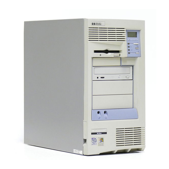
Package for the Minitower Models Front view with cover removed 24X CD-ROM drive Rear view Main memory Modules 1 System Overview Package for the Minitower Models Video Memory Upgrade Six accessory board slots Hard disk drive Serial Mouse Keyboard Display Parallel (All icons shown here are for information, and do not nec-... -
Page 14: Hp Kayak Xa Pc Workstation Overview
1 System Overview HP Kayak XA PC Workstation Overview HP Kayak XA PC Workstation Overview Component 233, 266 or 300 MHz Pentium II MMX processor with 512 KB cache memory Microprocessor Three DIMM sockets using: Main memory 32 MB, 64 MB or 128 MB ECC SDRAM to a maximum of 384 MB, or... -
Page 15: Hardware Control Panel
Hardware Control Panel Desktop Hardware Control Panel Power On Status Light Power On/Off Button Volume Control Minitower Hardware Control Panel Power On/Off Button Volume Control Hard Disk Activity Network Activity Light Light Speaker Out for Headset Hard Disk Activity Power on Status... -
Page 16: Specifications And Characteristic Data
1 System Overview Specifications and Characteristic Data Specifications and Characteristic Data Physical Characteristics Desktop Weight (excluding display and keyboard) Dimensions Footprint Keyboard Minitower Weight (excluding display and keyboard) Dimensions Footprint Keyboard Electrical Specifications Desktop Parameter Input voltage Power Voltage range... - Page 17 Desktop Parameter Efficiency Output Voltage Regulation Overvoltage Protection Isolation Voltage Safety Standard Maximum input current Current at +5 V Current at +3.3 V Total cumulated current on +3.3 V and +5 V Current at -5 V Current at +5V standby...
- Page 18 1 System Overview Specifications and Characteristic Data Desktop Parameter Power Voltage range Frequency range Maximum input current Input Surge Current Protection Safety Ground Leakage Current Efficiency Output Voltage Regulation Overvoltage Protection Isolation Voltage Safety Standard Output Voltage Regulation Current at +5 V Current at +3.3 V...
- Page 19 Current at -12 V Note that even though the desktop power supply is autoselect, it is not a full range power supply. It works in 2 input voltage range and not in one big 90 V to 240 V range.
-
Page 20: Environmental Specifications (Desktop And Minitower)
1 System Overview Specifications and Characteristic Data Environmental Specifications (Desktop and Minitower) Environmental Specifications (System Processing Unit, with Hard Disk) Operating Temperature Recommended Operating Temperature Storage Temperature Over Temperature Shutdown Operating Humidity Storage Humidity Acoustic noise emission: Sound power Sound pressure... -
Page 21: Documentation
HP Kayak XA PC Workstations. Only selected publications are available on paper. Most are available as viewable files (which can also be printed) from the HP division support servers, and on the HP Support Assistant CD-ROM. HP Kayak XA PC Workstation User’s... -
Page 22: Where To Find The Information
1 System Overview Documentation Where to Find the Information The following table summarizes the availability of information within the HP Kayak XA PC Workstation documentation set. User Guide Key features Product features Product model numbers Keyboard, mouse, display, Connecting cables and... - Page 23 Jumpers, switches and connectors How to replace Upgrading Peripheral Devices Setting up, configuring and troubleshooting Setting up and configuring “Access HP World Wide Web” on page 1 System Overview Technical Service Reference Guide Handbook Manual Jumpers, Jumpers, switches switches and...
- Page 24 1 System Overview Documentation...
-
Page 25: System Board
System Board This chapter describes the components of the system board, taking in turn the components of the Processor-Local Bus, the Peripheral Component Interconnect (PCI) bus, the System Management (SM) bus and the Industry Standard Architecture (ISA) bus and the AGP Accelerated Graphics Port Controller. -
Page 26: System Board And Backplane Boards
2 System Board System Board and Backplane Boards System Board and Backplane Boards Both desktop and minitower models have an AGP graphics controller built into the system board. . Also includes: SCSI Led and external SCSI cable detection. - Page 27 This slot can be used for a 32-bit PCI board (maxi- mum length 16-cm/6.3-inch). Device Can be used for a Can be used Desktop Backplane PCI Mapping Table [xx] System Board and Backplane Boards PCI Device Slot 440LX PAC...
- Page 28 2 System Board System Board and Backplane Boards Minitower Backplane Slots 5 and 6. These slots can be used (top view) for full-length 16-bit ISA boards. Slot 4. These slots can be used for a 16-bit ISA or a 32-bit PCI board. Slots 2 and 3.
-
Page 29: Architectural View
Architectural View Address (32) Control Data (64) PCI Bus (32 bit, 33 MHz) ISA Bus (16 bit, 8.25MHz) 29F002T Flash EEPROM Intel Pentium II Processor 440 LX PAC Cirrus 82443LX CL5465 PCI/ISA Bridge (PIIX4) 82371AB Interrupt Ultra DMA Controller Controller PCI Bus ISA Bus Interface... -
Page 30: Chip-Set
2 System Board Chip-Set Chip-Set The Intel AGPset is comprised of two chips. The 440LX PAC chip and the PIIX4chip. • The PAC chip (440LX) is the bridge between four buses: the PL (GTL) bus, the main memory bus, the PCI bus and the AGP (graphic) bus. •... - Page 31 AGP Bus Interface A controller for the AGP (Accelerated Graphics Port) slot is integrated in the 440LX PAC chip. The PAC chip supports only a synchronous AGP interface, coupling to the host bus frequency. The AGP characteristics are described in detail in Main Memory Controller The main memory controller supports three DIMM slots.
-
Page 32: The Piix4, Pci/Isa Bridge Chip (82371Ab)
2 System Board Chip-Set The PIIX4, PCI/ISA Bridge Chip (82371AB) The universal host controller interface (UHCI) chip, known as PIIX4, is encapsulated in a Ball Grid Array (BGA) package. The PIIX4 chip is a multi-function PCI device implementing a PCI-to-ISA bridge function, a PCI IDE function, a Universal Bus host/hub function, and an Enhanced Power Management function. - Page 33 PCI Bus Interface This part of the chip is responsible for transferring data between the PCI bus and the ISA expansion bus. It performs PCI-to-ISA, and ISA-to-PCI bus cycle translation. It supports the Plug-and-Play mechanism. Data buffers are provided, to isolate the PCI and ISA buses. Refer to of the devices on the PCI Bus.
-
Page 34: Cache Memory
2 System Board Chip-Set and slave controllers are connected. Counter / Timer The chip contains a three-channel 82C54 counter/timer. The counters use a division of the 14.318 MHz OSC input as the clock source. Serial EEPROM This is the non-volatile memory which holds the values for the Setup program (they are no longer stored in the CMOS memory). -
Page 35: Devices On The Processor-Local Bus
Devices on the Processor-Local Bus The Processor-Local (PL) bus of the Pentium II processors, also referred to as their FSB (Front Side Bus), is implemented in the GTL+ technology. This technology features open-drain signal drivers that are pulled-up to 1.5 V through 56 ohm resistors on both ends of the bus;... - Page 36 2 System Board Devices on the Processor-Local Bus The heat-sink is supplied with the processor, and is bolted to it by the manufacturer. The module is held in place by a bracket. There are two plastic clips, one on the top of each pillar of the bracket, to hold the processor module in place.
- Page 37 4.5. Switches 1 and 2, on the system board switches, set the frequency of the Processor-Local bus, which for all HP Kayak XA PC Workstation models, is 66 MHz. Switches 3, 4 and 5 set the clock multiplier ratio.
-
Page 38: Main Memory Bus
There are three 168-pin DIMM slots on the system board for installing main memory; slots A, B and C. All HP Kayak XA PC Workstation models are supplied with one memory module (either 16 MB, 32 MB or 64 MB ECC SDRAM) in one of the three slots, leaving the other slots free for memory upgrades. -
Page 39: Devices On The Pci Bus
IDE controller USB Host controller Power Management and SM Bus PCI slot #1 (LAN) - Minitower Backplane Rear Board - Desktop PCI slot #2 - Minitower PCI slot #1 - Desktop PCI slot #3 - Minitower PCI slot #2 - Desktop... -
Page 40: Universal Serial Bus (Usb) Controller
Over-current detection and protection is provided, but shared between the two ports. USB works only if the USB interface has been enabled within the HP Setup program. Currently, only the Microsoft Windows 95 and Windows NT operating systems provides support for the USB. -
Page 41: Accelerated Graphics Port (Agp) Controller
The AGP technology was developed as a means to access system memory as a viable alternative to augmenting the memory of the graphics subsystem needed for high quality 3D graphics applications. All models of HP Kayak XA PC Workstations support an AGP (Accelerated Graphics Port) device (Laguna Graphic Controller from Cirrus). - Page 42 2 System Board Accelerated Graphics Port (AGP) Controller AGP PCI Bus In the below diagram, the AGP Bus is viewed as a PCI bus with extra data lines. Implementation Device 66 MHz PCI Bus LX-Device 1 AGP Port Virtual PCI-PCI Bridge 33 MHz Pentium II Processor 440 LX - Device 0...
-
Page 43: Devices On The Sm Bus
Devices on the SM Bus Device PIIX4 SM Bus Master Serial EEPROM LM75 SDRAM slot 1 SDRAM slot 2 SDRAM slot 3 The System Management (SM) bus is used to monitor several of the hardware functions (such as voltage levels, temperature, fan speed, DIMM presence and type) of the system board. -
Page 44: Lm75 Chip
2 System Board Devices on the SM Bus LM75 Chip The LM75 chip is a temperature sensor and alarm located on the system board. It is used to measure the temperature in one area of the PC Workstation, and to send an alarm to the processor in case of overheating. This chip includes a security mechanism which prevents the system fan from being disabled using software controls so long as the temperature measured by the sensor is above the maximum operating temperature. -
Page 45: Devices On The Isa Bus
Bidirectional mode (PC/XT, PC/AT, and PS/2 compatible). Enhanced mode (enhanced parallel port, EPP, compatible). High speed mode (MS/HP extended capabilities port, ECP, compatible). The integrated flexible disk controller (FDC) supports any combination of two of the following: tape drives, 3.5-inch flexible disk drives, 5.25-inch flexible disk drives. -
Page 46: Audio Controller
Devices on the ISA Bus Audio Controller The HP Kayak XA PC Workstation has an audio chip (AD1816) integrated on the system board. This single chip is a Plug and Play multimedia audio subsystem for concurrently processing multiple digital streams of 16-bit stereo audio. -
Page 47: Flash Eeprom
Power-On Self-Test routines, video BIOS, plus their error messages). These are summarized in Chapters 4 and 5. The Flash EEPROMs on the HP Kayak XA PC Workstation implement a bootblock feature which allows recovery from a failed attempt at updating the System BIOS. -
Page 48: System Board Switches
2 System Board Devices on the ISA Bus System Board Switches The first two of the system board switches set the frequency of the Processor-Local bus, and the next three the ratio of processor-frequency to Processor-Local-bus-frequency, as summarized on The next five switches set the configuration for the PC Workstation, as summarized in the table below. - Page 49 2 Turn off the computer. Set Switch 9 to the Closed position. 3 Insert the DOS-bootable diskette. H = HP Professional PC C = Kayak XA (Pentium II models) 1 = Kayak family x = major revision yy = minor revision...
-
Page 50: Little Ben
The System ROM can be updated with the latest BIOS firmware. This can be downloaded from HP’s World Wide Web site: http://www.hp.com/go/kayaksupport To download a BIOS upgrade, connect to the HP Web site and follow the on- screen instructions to download the flash utility programs ( AUTOEXEC.BAT called Before updating the System ROM, it is necessary to disable the “PSWRD”... -
Page 51: Other Isa Accessory Devices
Other ISA Accessory Devices ISA accessory boards are for slow peripheral accessories. A diagram showing the ISA slots that are available for the desktop and minitower models is on Plug and Play All PCI accessory boards are Plug and Play, although not all ISA boards are. - Page 52 2 System Board Devices on the ISA Bus...
-
Page 53: Interface Devices And Mass-Storage Drives
Interface Devices and Mass-Storage Drives This chapter describes the graphics, mass storage and audio devices which are supplied with the computer. It also summarizes the pin connections on the internal and external connectors. -
Page 54: Cirrus 5465 Graphics Controller Chip
Cirrus 5465 Graphics Controller Chip Cirrus 5465 Graphics Controller Chip The HP Kayak XA PC Workstation Desktop and Minitower models are supplied with a Cirrus 5465 graphics controller chip integrated on the system board (refer to the architectural view on This chip integrates the necessary hardware for a flexible multimedia display system. - Page 55 • Green power saving features. • GUI acceleration width (in bits). • Hardware acceleration of graphical user interface (GUI) operations through a bit-block transfer mechanism. • Hardware cursor. • Integrated programmable, dual-clock synthesizer. • Integrated triple 8-bit DAC. • Integrated 24-bit, 135 MHz RAMDAC. •...
-
Page 56: Connectors
Video Memory The HP Kayak Workstation PCs are supplied with 4 MB of video memory integrated on the system board (revision B). There is either, an on-board 4 MB video memory soldered onto the system board. Or, 2 MB of built-in video memory (revision A) and a 2 MB video memory module installed in the video memory upgrade socket, giving 4 MB in total. -
Page 57: Available Video Resolutions
Available Video Resolutions The number of colors supported is limited by the graphics device and the video memory. The resolution/color/refresh-rate combination is limited by a combination of the display driver, the graphics device, and the video memory. If the resolution/refresh-rate combination is set higher than the display can support, you risk damaging the display. -
Page 58: Scsi / Lan Combo Board
SCSI / LAN Combo Board SCSI / LAN Combo Board Certain HP Kayak XA PC Workstations are supplied with an integrated SCSI / 10BT/100TX LAN combo board. Because the SCSI / LAN combo board includes two controllers, only one PCI slot is necessary for installing this board. -
Page 59: Scsi Interface
10BT/100TX PCI LAN The LAN adapter supports the following two standards: 100 VG-AnyLAN, 100 Mbits per second over 4-pair, category-3, unshielded twisted pair Connector (UTP), voice grade (VG) cable (IEEE 802.12 standard for Ethernet); 10 BaseT, 10 Mbits per second, ISO 8802-3 (IEEE 802.3 standard). On the rear panel there is one RJ-45 unshielded-twisted-pair (UTP) connector. -
Page 60: Scsi / Pci Lan Combo Board Features
3 Interface Devices and Mass-Storage Drives SCSI / LAN Combo Board By default, the internal SCSI bus is configured to run in Ultra-SCSI mode (providing a maximum band-width of 40 MB/s. The user may configure the SCSI system using the SCSI Configuration Utility, included in the system BIOS. -
Page 61: 10Bt/100Tx Lan Controller
10BT/100TX LAN Controller Certain models of the HP Kayak XA PC Workstation are supplied only with a 10BT/100TX LAN adapter which supports the following standards: 100 Mbits per second over 2-pair, category-5, unshielded twisted pair (UTP), or shielded twisted pair (STP); 10 BaseT, 10 Mbits per second, ISO 8802-3 (IEEE 802.3 standard). -
Page 62: 10Bt/100Tx Lan Features
AMD based card may be available, but in order to use this tool on HP cards, only 29fxxx flash devices must be used. At present, no test has been carried out using this tool on HP cards. - Page 63 Also, remote boot can only work on one card. Therefore, if a customer wants to use two HP LAN cards without using HP LAN enhanced features (Remote boot, Remote power on), then there is no problem.
-
Page 64: Mass-Storage Drives
Maximum internal transfer rate 16.7/33 MB/s Maximum external transfer rate Flexible Disk Drives Both desktop and minitower models are supplied with the new bezelless version of the drive (either Sony or Alps). page 39. The flexible disk controller is 2.5 GB 4.3 GB... -
Page 65: Cd-Rom Drives
• CD-ROM data disc (Mode 1 and Mode 2). • Photo-CD Multisession. (CD-585-B) • CD Audio disc. • Mixed mode CD-ROM disc (data and audio). • CD-ROM XA, CD-I, CD-Extra, CD-R, CD-RW. HP product number Disc Diameter Data Block Size Storage Capacity Read Mode Burst Transfer Rate... -
Page 66: Connectors And Sockets
3 Interface Devices and Mass-Storage Drives Connectors and Sockets Connectors and Sockets IDE and Flexible Disk Drive Connectors Status Panel Connector USB Stacked Connector IDE Connector Signal Signal Reset# Ground HD10 HD11 HD12 HD13 HD14 HD15 Ground 7 orientation key DMARQ Ground 2 DIOW#... - Page 67 Power Supply Connector Power Supply Connector for System Board Battery Pack Connector Power Supply 3V3 for System PCI Wakeup Connector Power Supply 3V3 on Backplane Fan Connector on Backplane ExtStart Connector Signal Signal PwrGood Remote On Ground Ground Ground +12 Volt supply 5V STDBY +5 Volt supply +5 Volt supply...
- Page 68 3 Interface Devices and Mass-Storage Drives Connectors and Sockets 16-Bit SCSI Connector 8-Bit SCSI Connector 16-Bit SCSI Connector Signal Signal not connected not connected not connected not connected not connected not connected not connected not connected not connected not connected not connected not connected not connected...
- Page 69 Internal Audio CD AUDIO Connector Connectors Analog Ground CD Right Channel Analog Ground CD Left Channel Audio Front Panel Connector Analog Ground Key Way Front Panel input Left Front Panel Return Left Front panel Input Right Front Panel Return Right OUT Volume Low Limit Volume High Limit Volume Adjust Left...
- Page 70 3 Interface Devices and Mass-Storage Drives Connectors and Sockets VGA DB15 Connector VESA Pass-Through Connector VGA DB Connector Pins Standard VGA DDC2B Analog RED Analog RED Analog GREEN Analog GREEN Analog BLUE Analog BLUE Monitor ID2 Monitor ID2 DDC return Analog RED return Analog RED Analog GREEN return...
- Page 71 3 Interface Devices and Mass-Storage Drives Connectors and Sockets Socket Pin Layouts Ethernet UTP Connector VGA Connector Keyboard and Mouse Connector Parallel Port Connector Serial Port Connector...
- Page 72 3 Interface Devices and Mass-Storage Drives Connectors and Sockets...
-
Page 73: Hp Bios
HP BIOS The Setup program and BIOS are summarized in the two sections of this chapter. The POST routines are described in the next chapter. -
Page 74: Hp/Phoenix Bios Summary
The system BIOS is identified by the version number HC.11.xx. The procedure for updating the System ROM firmware is described on Using the HP Setup Program Press , to run the Setup program, while the initial “Kayak” logo is being displayed immediately after restarting the PC. -
Page 75: Advanced Menu
• PCI Devices. Enable this option if you need the BIOS to set the PCI Bus Master bit. This could be necessary for some older PCI accessory boards. • ISA Resource Exclusion. reserves interrupts for legacy ISA devices to prevent conflict with PCI/PnP devices. 4 HP BIOS HP/Phoenix BIOS Summary... -
Page 76: Security
4 HP BIOS HP/Phoenix BIOS Summary Security Sub-menus are presented for changing the characteristic and values of the System Administrator Password, User Password, Hardware Protection and Boot Device Security, the amount of protection against the system’s drives and network connections, and the amount of protection against being able to boot from the system’s drives and network connections. -
Page 77: Symbios Logic Scsi Configuration Utility
Read Write I/O Timeout (secs) Scan for Devices at Boot Time Scan for SCSI LUNs Queue Tags Symbios Logic SCSI Configuration Utility during the power-on self test (after Default Settings Enabled Low to High (0-Max) Default Settings Enabled 4 HP BIOS... -
Page 78: Starting The Scsi Configuration Utility
4 HP BIOS Symbios Logic SCSI Configuration Utility Starting the SCSI Configuration Utility You access the SCSI Configuration Utility by pressing when the message is displayed during the Press F6 to start Configuration Utility... PC Workstation’s start-up routine. A further message is then displayed: before the Main Please wait, invoking Configuration Utility... -
Page 79: Power Saving And Ergonometry
<25 W (230V, 50 Hz) <27 W (115V, 60 Hz) <21 W (115V, 60 Hz) Keyboard, mouse Keyboard, mouse, network (RPO) Instantaneous a few seconds 4 HP BIOS Power Saving and Ergonometry Suspend Shutdown Halted Blanked, <5 W (typ) Halted <5 W... -
Page 80: Bios Addresses
4 HP BIOS BIOS Addresses BIOS Addresses This section provides a summary of the main features of the HP system BIOS. This is software that provides an interface between the computer hardware and the operating system. The procedure for updating the System ROM firmware is described on... -
Page 81: Hp I/O Port Map (I/O Addresses Used By The System)
HP I/O Port Map (I/O Addresses Used by the System Peripheral devices, accessory devices and system controllers are accessed via the system I/O space, which is not located in system memory space. The 64 KB of addressable I/O space comprises 8-bit and 16-bit registers (called I/O ports) located in the various system components. -
Page 82: Dma Channel Controllers
4 HP BIOS BIOS Addresses I/O Address Ports 0378 - 037A 0388 - 038B 03B0 - 03DF 03E8 - 03EF 03F0h- 03F5 03F6 03F7 03F8 - 03FF 04D0 - 04D1 0678 - 067B 0778 - 077B 0CF8 - 0CFF DMA Channel Controllers Only “I/O-to-memory”... -
Page 83: Interrupt Controllers
However, optional system performance is reached when minimizing the sharing of interrupts. Refer to pages tower Backplane PCI Mapping tables, and device interrupts. for the Desktop and Mini- page 39 for a table of the PCI 4 HP BIOS BIOS Addresses... - Page 84 4 HP BIOS BIOS Addresses...
-
Page 85: Power-On Self-Test And Error Messages
Power-On Self-Test and Error Messages This chapter describes the Power-On Self-Test (POST) routines, which are contained in the computer’s ROM BIOS, the error messages which can result, and the suggestions for corrective action. -
Page 86: Order In Which The Tests Are Performed
The POST process verifies the basic functionality of the system components and initializes certain system parameters. The POST starts by displaying a graphic screen of the HP PC Workstation’s logo when the PC is restarted. If you wish to view the POST details, press to get the HP Summary Screen. - Page 87 The following table lists the POST checkpoint codes written at the start of each test. Checkpoint Code Verify Real Mode Disable Non-Maskable Interrupt (NMI) Get CPU type Initialize system hardware Initialize chipset with initial POST values Set IN POST flag Initialize CPU registers Enable CPU cache Initialize caches to initial POST values...
- Page 88 5 Power-On Self-Test and Error Messages Order in Which the Tests are Performed Checkpoint Code Clear 512 KB base RAM Test CPU bus-clock frequency Initialize POST Dispatch Manager Test CMOS RAM Initialize alternate chipset registers Warm start shutdown Reinitialize the chipset (MB only) Shadow system BIOS ROM Reinitialize the cache (MB only) Autosize cache...
- Page 89 Checkpoint Code Test keyboard Set key click if enabled Enable keyboard Initialize POST display service Display prompt “Press F2 to enter SETUP” Disable CPU cache Test RAM between 512 and 640 KB Test extended memory Test extended memory address lines Jump to UserPatch1 Configure advanced cache registers Initialize Multi Processor APIC...
- Page 90 5 Power-On Self-Test and Error Messages Order in Which the Tests are Performed Checkpoint Code Late POST device initialization Detect and install external RS 232 ports Configure non-MCD IDE controllers Detect and install external parallel ports Initialize PC-compatible PnP ISA devices Re-initialize onboard I/O ports Configure Motherboard Configurable Devices Initialize BIOS Data Area...
- Page 91 Checkpoint Code Determine number of ATA and SCSI drives Set time of day Check key lock Initialize typematic rate Erase F2 prompt Scan for F2 key stroke Enter SETUP Clear IN POST flag Check for errors POST done - prepare to boot operating system Terminate QuietBoot Check password (optional) Clear global descriptor table...
- Page 92 5 Power-On Self-Test and Error Messages Order in Which the Tests are Performed Checkpoint Code The following are for boot block in Flash ROM Initialize the chipset Initialize the bridge Initialize the CPU Initialize system timer Initialize system I/O Check force recovery boot Checksum BIOS ROM Go to BIOS Set Huge Segment...
-
Page 93: Error Message Summary
Error Message Summary The EMU utility (.COM application written in C language) is to provide full screen online help messages (localized) on most common POST errors. When an error is generated in POST during the boot process, EMU is run by typing ENTER. - Page 94 5 Power-On Self-Test and Error Messages Error Message Summary The following table list the error codes, causes and symptoms and the accompanied short message that are displayed in the upper left corner of the screen. Code # Cause / Symptom 0000h Any POST error that is not listed below 0010h...
- Page 95 Code # Cause / Symptom 0310h Floppy A: not detected (but configured in CMOS) 0311h Floppy B: not detected (but configured in CMOS) 0305h Floppy A: plugged on Floppy B: connector 0306h General failure on floppy controller 0307h Conflict on floppy disk controller 0400h CD-ROM test failure 0401h...
- Page 96 5 Power-On Self-Test and Error Messages Error Message Summary Code # Cause / Symptom 0731h Defective SIMM (module 1, bank 3) 0732h Defective SIMM (module 2, bank 3) 0800h Found lower cache size than configured 0801h Cache self-test failure 0900h Lan (Chanteclerc) self-test failure 0901h Lan (Chanteclerc) not detected (but enabled in Setup)
-
Page 97: Beep Codes
Beep Codes If a terminal error occurs during POST, the system issues a beep code before attempting to display the error in the upper left corner of the screen. Beep codes are useful for identifying the error when the system is unable to display the error message. -
Page 98: Lights On The Hardware Control Panel
5 Power-On Self-Test and Error Messages Lights on the Hardware Control Panel Lights on the Hardware Control Panel When the computer is first powered on, the power-on light on the status panel illuminates yellow for about a second before changing to green. This change of color is caused by the execution of an instruction early in the System BIOS code. -
Page 99: Appendix
Appendix... -
Page 100: Video Modes
Appendix Video Modes Video Modes Standard VGA Modes ® Mode VESA No. of Colors 0, 1 0, 1 16/256K 2, 3 2, 3 16/256K 4, 5 4, 5 4/256K 2/256K Monochrome 16/256K 16/256K Monochrome 16/256K 2/256K 2/256K 16/256K 16/256K 256/256K Interlaced mode. -
Page 101: Extended Video Modes
Extended Video Modes ® Mode VESA No. of Colors 256/256K 256/256K 256/256K 256/256K 256/256K 16M+A 16M+A 16M+A 16M+A 58, 6A 16/256K 58, 6A 16/256K 58, 6A 16/256K 58, 6A 16/256K 58, 6A 16/256K 256/256K Char. x Char. x Resolution Cell 80 x 25 8 x 16 640 x 400... - Page 102 Appendix Video Modes ® Mode VESA No. of Colors 256/256K 256/256K 256/256K 256/256K 16M+A 16M+A 16M+A 16M+A 16M+A 16/256K 16/256K 16/256K 16/256K 16/256K 256/256K Char. x Char. x Resolution Cell 100 x 37 8 x 16 800 x 600 100 x 37 8 x 16 800 x 600 100 x 37...
- Page 103 ® Mode VESA No. of Colors 256/256K 256/256K 256/256K 256/256K 16M+A 16M+A 16M+A 16M+A 16M+A 16/256K 16/256K 16/256K 16/256K 16/256K 256/256K Char. x Char. x Resolution Cell 128 x 48 8 x 16 1024 x 768 128 x 48 8 x 16 1024 x 768 128 x 48 8 x 16...
- Page 104 Appendix Video Modes ® Mode VESA No. of Colors 256/256K 256/256K 256/256K 256/256K 256/256K 256/256K 16M colors, but with 32-bit-per-pixel format. +A indicates 16M colors + Alpha Channel Interlaced mode. NOTE An 8 x 14 font for mode 55h is provided with a DOS TSR (terminate and stay resident) program.
-
Page 105: Maximum Refresh Rates
Maximum Refresh Rates Resolution 1024 x 768 1280 x 1024 1600 x 1200 BIOS Modes Supported ® VESA Cirrus Mode Mode Logic Mode No. 0, 1 2, 3 4, 5 Cirrus Logic VESA 170-MHz DAC 230-MHz DAC 100+ Hz 100+ Hz 85 Hz 100+ Hz 60 Hz... - Page 106 Appendix Video Modes ® VESA Cirrus Mode Mode Logic Mode No. VESA VESA VESA Cirrus Logic VESA 58, 6A VESA VESA VESA Cirrus Logic VESA VESA VESA VESA Cirrus Logic VESA Text bpp 1024 1024 1024 1024- 1024 1024 1280 1024 Refresh Mode...
- Page 107 ® VESA Cirrus Mode Mode Logic Mode No. VESA VESA Cirrus Logic 16 bpp is 5:6:5 (RGB); 24 bpp is 24 bpp packed pixel; 32 bpp is 24 bpp packed into a 32-bit dword. “V” indicates VGA compatible mode; “S” indicates Super VGA mode; “L”...
- Page 108 Appendix Video Modes...