
Related Manuals for GE MRIaudio 1505


Summary of Contents for GE MRIaudio 1505
- Page 1 Installation and User Guide Models 1505 and 1506 (858) 427-0679 support@mriaudio.com www.mriaudio.com...
-
Page 2: Table Of Contents
I N S T A L L A T I O N A N D U S E R G U I D E T A B L E O F C O N T E N T S DE VI CE D ESC R IPT IO N Warnings and Cautions . -
Page 3: Warnings And Cautions
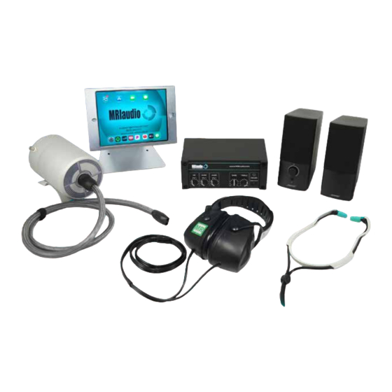
Patient Comfort through Sound DEVICE DESCRIPTION The MRIaudio Sound System is an MRI conditional audio solution that provides MRI patients with music, direct communication from the technologist and 29 dB hearing protection . WARNINGS AND CAUTIONS Please read this manual and follow its instructions carefully . The words, WARNING, CAUTION and NOTE carry special meaning and should be carefully reviewed: WARNING: Indicates risk to the safety of the patient or technologist . -
Page 4: Indications Of Use
I N S T A L L A T I O N A N D U S E R G U I D E • Do not modify this equipment in any way . • Never use the system in the presence of flammable or explosive gases. It is critically important that only MR Safe and MR Conditional components be taken into and installed in the MRI suite . -
Page 5: System Component Classifications
S O U N D S Y S T E M C O M P O N E N T S SYSTEM COMPONENT CLASSIFICATIONS MR SAFE This device is classified as completely nonmagnetic, non-electrically conductive and non-radio frequency reactive . This eliminates all primary and potential risks during MRI scanning . MR CONDITIONAL This system component may contain magnetic, electrically conductive or radio frequency-reactive parts . -
Page 6: Mr Safe Components
S O U N D S Y S T E M C O M P O N E N T S MRI SAFE COMPONENTS These system components are MR SAFE and can be used within the MRI bore during a scan . In-Ear Headphones Over-Ear Headphones Headphone Covers... -
Page 7: System Component Descriptions And Part Numbers
SYSTEM COMPONENT DESCRIPTIONS AND PART NUMBERS PRIMARY COMPONENT SPECIFICATIONS DIMENSIONS WEIGHT NAME PART # GE PART # (L x W x H - IN.) (LBS.) Digital Amplifier 5759312 9 x 6 x 3 .5 3 .2 Technologist Speakers 3 .5 x 6 x 7 .5 3 .3... - Page 8 Integrates AutoVoice features with MRIaudio system . AutoVoice Adapter Connects to control computer with Digital Amplifier. 5759317 (25-pin) 12’ cable has 25-pin connector . For GE MRI models: Discovery™ Integrates AutoVoice features with MRIaudio system . AutoVoice Adapter Connects to control computer with Digital Amplifier. 12’...
-
Page 9: System Map Overview - Model #S 1505 And 1506
S Y S T E M M A P O V E R V I E W S For MRIaudio Premium Sound System Model #1505 and 1506 using AutoVoice Adapter. The map diagram below provides an installation overview of the system that utilizes the 15 or 25-pin AutoVoice Adapter . -
Page 10: Ins Tallat Io N
I N S T A L L A T I O N 1. 100’ DB9 CABLE INSTALLATION The following steps will walk you through the process for running the 100’ cable from the Digital Amplifier to the penetration panel in the computer room. 1.1 Using a mini screwdriver, loosen, then remove the 2-pin terminal clip attached to the pigtail end of the 100’... -
Page 11: Penetration Panel Connections
2. CONNECT 100’ DB9 CABLE TO PENETRATION PANEL 2.1 In the computer room, connect Penetration Panel Penetration Panel J17 OR OTHER the DB9 end (A) to J16, J17, or J18 OPEN PORT (B) on the penetration panel (Fig . 3) . Record the port used, as you will be connecting the 45’... -
Page 12: Sonic Transducer
I N S T A L L A T I O N 5. INSTALL SONIC TRANSDUCER WARNING: The Sonic Transducer is MR CONDITIONAL and must be kept at least 3’ away from the bore at all times . Exercise extreme caution when handling it until it is mounted . -
Page 13: Mounting Headphones
6. MOUNT HEADPHONES 6.1 Remove the sticker backing on the Over-Ear Headphone mount . Attach to the side of MRI machine approximately 4-5 feet off ground (Fig . 14) . Remove the sticker backing on the In-Ear Headphone hanger and attach under Over-Ear mount . Clamp the two headphones as shown (Fig . -
Page 14: Digital Amplifier Assembly
. If necessary, use the Universal Power Adapter (670-10) to adapt the power cords to your locality . If installing on a GE magnet, connect the Digital Amplifier power supply or Universal Power Adapter to the power strip inside the GOC . -
Page 15: Control Room Component Assembly
8. CONTROL ROOM COMPONENT ASSEMBLY PRONGS 8.1 The power cord for the amplifier 8.2 Plug the Bose Speakers terminal 8.3 Plug the other end of the Bose has two bayonet-style prongs . Line clip (670-10) into the slot labeled Speakers connection cord into the up the prongs with the hole labeled ZONE 2 OUTPUTS. -
Page 16: Autovoice Adapter Connection
I N S T A L L A T I O N 9. AUTOVOICE ADAPTER CONNECTION Depending on the MRI machine model, you will be installing a 15-pin (685) or 25-pin (680) AutoVoice Adapter in the machine’s console PC . 9.1 Open the case of the console PC . -
Page 17: E R G U Ide
U S E R G U I D E iPad INTERFACE VOLUME SUPPORT The iPad Mini arrives pre- configured and is ready to use right away . Slide the iPad POWER HOME BUTTON into the locking mount and secure in place . Lock combo is 0000 . -
Page 18: How To Use The System
U S E R G U I D E 10. HOW TO USE SYSTEM 10.1 POWER ON THE SYSTEM 10.2 SELECT STREAMING SERVICE 10.3 ADJUST iPAD VOLUME Depress the power button on the lower Have the patient select a streaming app, In order for the audio to work properly, the right of the Digital Amplifier. -
Page 19: Troubleshooting
U .S . Food and Drug Administration . Are MRIaudio systems OEM compatibility? MRIaudio systems are compatible with all OEMs, including GE, Siemens, Philips, Hitachi, and Canon (formerly Toshiba) MRIs . -
Page 20: Emc Information
U S E R G U I D E EMC INFORMATION Guidance and Manufacturer’s Declaration – Electromagnetic Immunity The MRIaudio Sound System is intended for use in the electromagnetic environment specified below. The customer or the user of the MRIaudio Sound System should assure that it is used in such an environment . EMISSIONS TEST &... - Page 21 EMC INFORMATION IMMUNITY TEST IEC 60601 TEST COMPLIANCE LEVEL ELECTROMAGNETIC ENVIRONMENT - GUIDANCE AND STANDARD LEVEL 3 Vrms Portable and mobile RF communications equipment 0,15 – 80 MHz should be used no closer to any part of the Conducted RF 6 V in ISM bands be- MRIaudio Sound System, including cables, than the 3 Vrms...
-
Page 22: Contact Information
P A T I E N T C O M F O R T T H R O U G H S O U N D Founded by Spencer Howe in 2010, MRIaudio is fully dedicated to providing the absolute best in MRI patient comfort equipment and customer service for diagnostic imaging professionals and their patients worldwide. ...