
Related Manuals for HP ProCurve 4202vl-48G


Summary of Contents for HP ProCurve 4202vl-48G
- Page 1 ProCurve Series 4200vl Switches www.procurve.com Installation and Getting Started Guide...
- Page 3 ProCurve Switch 4200vl Series Installation and Getting Started Guide...
- Page 4 Nothing herein should be construed as constituting an additional warranty. HP shall not be liable for technical or editorial errors or omissions contained herein. Hewlett-Packard assumes no responsibility for the use or reliability of its software on equipment that is not furnished by Hewlett-Packard.
-
Page 5: Table Of Contents
2. Install Switch vl Modules ........ - Page 6 Hot Swapping Switch Modules ........2-22...
- Page 7 Downloading New Code ........4-14 HP Customer Support Services ........4-14 Before Calling Support .
- Page 8 C Safety and EMC Regulatory Statements Safety Information ..........C-1 Informations concernant la sécurité...
-
Page 9: Introducing The Procurve Switch 4200Vl Series
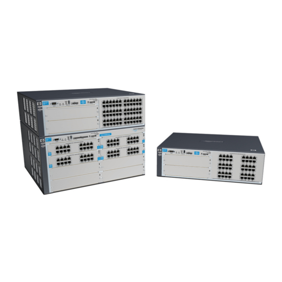
Switch 4200vl Options and Bundles The Switch 4200vl is available in the following options: ■ ProCurve Switch 4204vl (J8770A), a chassis with four open slots and comes in one bundle: • ProCurve Switch 4204vl-48GS (J9064A), consists of a J8770A Chassis with two pre-installed ProCurve Switch vl modules. - Page 10 Introducing the ProCurve Switch 4200vl Series Switch 4200vl Options and Bundles Figure 1-1. ProCurve Switch 4204vl (J8770A) Figure 1-2. ProCurve Switch 4208vl (J8773A)
- Page 11 Two slots for vl Modules Figure 1-4. ProCurve Switch 4202vl-48G (J8771A) Introducing the ProCurve Switch 4200vl Series Switch 4200vl Options and Bundles 72 fixed ports of 10/100-TX with HP Auto MDI-X 48 fixed ports of 10/100/1000-T with IEEE Auto MDI/MDI-X...
-
Page 12: Supported Modules
Introducing the ProCurve Switch 4200vl Series Switch 4200vl Options and Bundles Supported Modules: As of this printing, the supported vl modules are: • 12-port 100-FX vl Module (J8763A) • 16-port 10/100/1000-T vl Module (J8764A) • 24-port 10/100-TX vl Module (J8765A) •... -
Page 13: Front Of The Switch
ProCurve Switch 4200vl Series. LEDs As described in the next two tables, there are LEDs on the switch chassis and on the switch modules/ports that keep you informed of the status of the switch and the network connections. - Page 14 The Status LED for the module or other component with the fault will flash simultaneously. On briefly at the beginning of switch self test after the switch is powered on or reset. If on for a prolonged time, the switch has encountered a fatal hardware failure, or has failed its self test.
- Page 15 • no active network cable is connected to the port • the port is not receiving link beat or sufficient light • the port has been disabled through the switch console, the web browser Flashing The port has failed self test due to hardware failure or because the port type requires newer software in order to be recognized.
-
Page 16: Led Mode Select Button And Indicator Leds
The Mode Select button and LEDs are the same for all the Switch 4200vl Series. The following example is of a J8772A, 4202vl-72. 10/100Base-TX Ports — all ports are HP A uto MDI- X Link Mode... -
Page 17: Console Port
Console Port This port is used to connect a console to the switch by using the serial cable supplied with the switch. This connection is described under “Connecting a Console to the Switch” in chapter 2, “Installing the Switch 4200vl Series”. The console is a full-featured interface that can be used to configure, monitor, and troubleshoot the switch. -
Page 18: Back Of The Switch
Figure 1-7. Example showing back of Switch 4208vl (J8773A) Power Connector The Switch 4200vl Series do not have a power switch; they are powered on when connected to an active AC power source. The switches automatically adjust to any voltage between 100-127 and 200-240 volts and either 50 or 60 Hz. -
Page 19: Switch Features
Switch Features The features of the Switch 4200vl Series include: 2, 4 or 8 slots for installing any of the available Switch vl Modules. ■ the modules can be installed in any order and in any combination and can be “hot swapped”. - Page 20 ■ mance, security, and control— for a description, see the Management and Configuration Guide and the Advanced Traffic Management Guide for your switch, available on the ProCurve Web site. 1-12...
-
Page 21: Installing The Switch 4200Vl Series
Installing the Switch 4200vl Series The ProCurve Switch 4200vl Series are easily installed. They come with an accessory kit that includes the brackets for mounting the switch in a standard 19-inch telco rack, in an equipment cabinet, or on a wall. The switches have rubber feet already attached so they can be securely located on a horizontal surface. - Page 22 Installing the Switch 4200vl Series Included Parts ■ Power cord, one of the following: Australia/New Zealand China Continental Europe Denmark Japan J a p a n P o w e r C o r d W a r n i n g...
-
Page 23: Installation Procedures
Installation Procedures Summary Follow these easy steps to install your switch. The rest of this chapter provides details on these steps. Prepare the installation site ronment into which you will be installing the switch is properly prepared including having the correct network cabling ready to connect to the switch, and having a good location for the switch. -
Page 24: Installation Precautions
Installing the Switch 4200vl Series Installation Procedures N o t e The 10/100Base-TX ports on the10/100-TX vl Module have the HP Auto MDI-X feature, and the 10/100/1000Base-T ports on the Gig-T vl Module comply with IEEE 802.3ab standard which includes the Auto MDI/MDI- X feature. - Page 25 To determine the possibility of overloading the supply circuits, add together the ampere ratings of all devices installed on the same circuit as the switch and compare the total with the rating limit for the circuit. The maximum ampere ratings are usually printed on the devices near the AC power connectors.
-
Page 26: Prepare The Installation Site
For distances less than 20km, a 10dB attenuator must be used. For distances between 20km and 40km, a 5dB attenuator must be used. Attenuators can be purchased from most cable vendors. page B-1 Summary of Cable Types to Use with the Switch Length Limits Twisted-Pair Cables 100 meters Note: The ProCurve Gig-T vl Modules are compatible with the IEEE 802.3ab standard... -
Page 27: Installation Location
Before installing the switch, plan its location and orientation relative to other devices and equipment: ■ In the front of the switch, allow at least 7.6 cm (3 inches) of space for the twisted-pair and fiber-optic cabling. ■ In the back of the switch, allow at least 10.2 cm (4 inches) of space for the power cord and cooling. -
Page 28: Install Switch Vl Modules
Torx T-10 screwdriver. Retain the slot cover for future use. M o d u l e ■ Any of the supported Switch vl Modules can be installed in any of the slots. I n s t a l l a t i o n ■... - Page 29 Figure 2-1. Installing a module the module is fully inserted when the module bulkhead is contacting, or very close to contacting the face of the switch Figure 2-2. Tighten module retaining screws Installing the Switch 4200vl Series “Low-force” connector. High insertion force is not...
-
Page 30: Optional) Install Second Power Supply
3. (Optional) Install Second Power Supply A second, load-sharing redundant power supply (ProCurve Switch gl/xl/vl RPS, J4839A) can be installed in the back of the switch. To provide true redundancy, this second power supply should be connected to a different AC power source from the other supply. - Page 31 Insert the power supply into the opening, then slide it all the way in until it connects to the switch. The power supply face plate will be flush with the back face of the switch. Figure 2-3. Installing a power supply Once the power supply is installed, ensure you tighten the four retaining screws that hold it in place.
-
Page 32: Verify The Switch Passes Self Test
Figure 2-5. Connecting power to the Switch N o t e The Switch 4200vl Series do not have a power switch. They are powered on when the power cord is connected to the switch and to a power source. If your installation requires a different power cord than the one supplied with the switch, please see the “Installation Precautions”... -
Page 33: Led Behavior
• If the ports are not connected to active network devices, the LEDs will stay off. switch chassis LEDs 10/100Base-TX Ports — all ports are HP A uto MDI- X Mode Link Mode Mode Link... -
Page 34: Mount The Switch
5. Mount the Switch After the modules and optional power supply are installed and you have verified the switch passes self test, you are ready to mount the switch in a stable location. The Switch 4200vl Series can be mounted in these ways: in a rack or cabinet ■... - Page 35 10 mm M4 screws Figure 2-7. Attaching brackets to a 3U chassis 10 mm M4 screws Figure 2-8. Attaching brackets to a 5U chassis Installing the Switch 4200vl Series Installation Procedures 2-15...
- Page 36 Figure 2-9. Installing the Rack Screw Place the switch in the rack and lower it so the notches in the bottom of the bracket slide onto the screws, then tighten these screws. lower the switch with...
-
Page 37: Horizontal Surface Mounting
Place the switch on a table or other horizontal surface. Use a sturdy surface in an uncluttered area. You may want to secure the networking cables and switch power cord to the table legs or other part of the surface structure to help prevent people from tripping over the cords. -
Page 38: Wall Mounting
Installing the Switch 4200vl Series Installation Procedures Wall Mounting The mounting brackets supplied with the switch allow you to mount it on a wall. The illustrations below show mounting a Switch 4208vl. All other 4200vl Switches would be mounted in a similar way. -
Page 39: Connect The Switch To A Power Source
Diagnostic Tip Try the following procedures: Port LED is still off when • For the indicated port, verify both ends of the cabling, at the switch and the connected device, are a cable is securely connected. connected • Verify the connected device and switch are both powered on and operating correctly. -
Page 40: Optional) Connect A Console To The Switch
In-Band: Access the console using telnet from a PC or UNIX station on the network, and a VT-100 terminal emulator. This method requires that you first configure the switch with an IP address and subnet mask by using either out-of-band console access or through DHCP/Bootp. -
Page 41: Direct Console Access
If you want to operate the console using a different configuration, ensure you change the settings on both the terminal and on the switch. Change the switch settings first, then change the terminal settings, and reestablish the console session. Direct Console Access... -
Page 42: Hot Swapping Switch Modules
If a module has to be replaced with one of the same type, or you are expanding the switch capability by adding a module in a slot where one was not previ- ously installed (since the last switch reboot), the replaced or new module is immediately operational;... -
Page 43: Example Network Topologies
Notice the end node devices are connected to the switch by either straight- through or crossover twisted-pair cables. Either cable type can be used because of the “HP Auto MDI-X” feature on the 10/100-TX vl ports and the standard “Auto MDI/MDI-X” feature on the Gig-T vl Module to which the server is connected. -
Page 44: Legacy Connectivity
2 km. The 10/100-TX vl modules provide connectivity for printers, PCs, and legacy servers running at 100 mbps. 2-24 switch 4204vl 10/100Base-TX Ports — all ports are HP A uto MDI- X Link Mode Link... -
Page 45: Use As An Edge Switch
Installing the Switch 4200vl Series Example Network Topologies trunked redundant Gigabit fiber-optic links switch 4200vl 10/100Base-TX Ports — all ports are HP A uto MDI- X 10/100Base-TX Ports — all ports are HP A uto MDI- X Link Mode Link Mode... -
Page 46: Used As An Aggregation Switch
10-GbE uplink connection (expected throughput is 2.5 to 7 Gbps, depending on packet size). limited to at most 1 Gbps. Each Switch 4200vl Series can support up to 4 J8766A modules. The 10-GbE module supports trunking – however, it can only trunk 2, 10 Gigabit ports, and they cannot be mixed with other port speeds in the trunk. -
Page 47: Getting Started With Switch Configuration
Getting Started With Switch Configuration This chapter is a guide for using the console Switch Setup screen to quickly assign an IP (Internet Protocol) address and subnet mask to the switch, set a Manager password, and, optionally, configure other basic features. -
Page 48: Using The Switch Setup Screen
The quickest and easiest way to minimally configure the switch for manage- ment and password protection in your network is to use a direct console connection to the switch, start a console session, and access the Switch Setup screen. Using the method described in the preceding section, connect a terminal device to the switch and display the switch console command (CLI) prompt (the default display). - Page 49 Recommended; If you set IP Config to Manual, then enter an IP address Note: The IP address and subnet mask assigned for the switch must be compatible with the IP addressing used in your network. For more information on IP addressing, see the Management and Configuration Guide for your switch,...
-
Page 50: Where To Go From Here
The above procedure configures your switch with a Manager password, IP address, and subnet mask. As a result, with the proper network connections, you can now manage the switch from a PC equipped with Telnet, a web browser interface, or from an SNMP-based network management station using a tool such as ProCurve Manager. -
Page 51: Using The Ip Address For Remote Switch Management
4200vl Series, you can use the switch’s IP address to manage the switch from any PC that is on the same subnet as the switch. You can use either a Telnet session or a standard web browser to manage the switch. - Page 52 ProCurve Web site. An extensive help system is also available for the web browser interface. To access the help system though, the subnet on which the switch is installed must have access to the internet, or ProCurve Manager needs to be installed on a network management station that is on the subnet.
-
Page 53: Troubleshooting
Troubleshooting This chapter describes how to troubleshoot your Switch 4200vl Series. Note that this document describes troubleshooting mostly from a hardware perspective. You can perform more in-depth troubleshooting using the soft- ware tools available with the switch, including the full-featured console interface, the built-in web browser interface, and ProCurve Manager, the SNMP-based network management tool. -
Page 54: Basic Troubleshooting Tips
Use a new correctly-wired cable or compare your cable to the cable in appendix B, “Switch Ports and Network Cables” for pinouts and correct cable wiring. A category 5 cable tester is a recom- mended tool for every 100Base-TX and 1000Base-T network installation. - Page 55 Because the Switch 4200vl Series behave in this way (in compliance with the IEEE 802.3 standard), if a device connected to the switch has a fixed configuration at full duplex, the device will not connect correctly to the switch.
-
Page 56: Diagnosing With The Leds
Troubleshooting Diagnosing with the LEDs Diagnosing with the LEDs Tables 4-1 shows LED patterns on the switch and the switch modules that indicate problem conditions. Check in the table for the LED pattern you see on your switch Refer to the corresponding diagnostic tip on the next few pages. -
Page 57: Diagnostic Tips
If the power source and power cord are OK and this condition persists, the switch power supply may have failed. Call your HP-authorized LAN dealer, or use the electronic support services from HP to get assistance. See the Customer Support/ Warranty card for more information. - Page 58 Reconnect the power supply to the AC power source. If the error indication reoccurs after the supply is reinstalled, the power supply may be faulty. Call your HP- authorized LAN dealer, or use the electronic support services from HP to get assistance.
- Page 59 Ensure you have installed a vl module in the slot. ProCurve gl and xl modules will fit installed in the slot in the slot, but they are not compatible with your ProCurve vl switch. Check to ensure that corresponds to the module has a “vl module”...
- Page 60 For the Port Security feature, you can configure the switch so that whenever a for which the Link security violation is detected on a port, the switch will disable the port. When a port LED is flashing has is disabled by this feature, the port Link LED will be continuously flashed at the fast been disabled rate of 0.8 seconds per cycle.
- Page 61 The network Try the following procedures: connection is not • For the indicated port, verify both ends of the cabling, at the switch and the working properly. connected device, are securely connected. • Verify the connected device and switch are both powered on and operating correctly.
-
Page 62: Proactive Networking
■ performance of your network The following interfaces provide tests, indicators, and an event log that can be used to monitor the switch and its network connections, and to help you take advantage of these proactive networking features: ■ ProCurve Manager - an SNMP-based network management tool included... -
Page 63: Hardware Diagnostic Tests
Checking the Switch LEDs The self-test passes if the Fault and Self Test LEDs on the front of the switch go off after approximately 90 to 150 seconds depending on the number and type of modules installed in the switch. If these LEDs stay on longer than 180 seconds or begin flashing, the switch, or a module, or an individual mini-GBIC may have to be replaced as indicated by the LEDs. -
Page 64: Testing Twisted-Pair Cabling
HP also offers a wire testing service. Contact your HP-authorized LAN dealer or your local HP sales office for more information. Testing Switch-to-Device Network Communications... -
Page 65: Restoring The Factory Default Configuration
(usually disabling them) may result in network connectivity issues. If the switch has a valid configuration, and you are restoring the factory default settings for a reason other than configuration problems, you should save the switch configuration prior to performing the factory default reset. -
Page 66: Downloading New Code
Additionally, your HP-authorized network reseller can provide you with assis- tance, both with services that they offer and with services offered by HP. Before Calling Support Before calling your networking dealer or HP Support, to make the support... -
Page 67: Physical
• Switch 4204vl • Switch 4202vl-48G • Switch 4204vl-48GS • Switch 4202vl-72 Electrical The Switch 4200vl Series automatically adjust to any voltage between 100-127 and 200-240 volts and either 50 or 60 Hz. AC voltage: Maximum current: Frequency range: 44.2 cm (17.4 in) 38.86 cm (15.3 in) -
Page 68: Environmental
DIN 45635 T.19 Noise Emission LwA=63.1 dB in a virtual workspace according to DIN 45635 T.19 Switch 4204vl, 4202vl-48G, and 4202vl-72 and its bundles: Geräuschemission LwA=64.2 dB am fiktiven Arbeitsplatz nach DIN 45635 T.19 Noise Emission LwA=64.2 dB in a virtual workspace according to DIN 45635 T.19... -
Page 69: B Switch Ports And Network Cables
Switch Ports and Network Cables This appendix includes switch connector information and network cable information for cables that should be used with the Switch 4200vl Series, including minimum pin-out information and specifications for twisted-pair cables. N o t e Incorrectly wired cabling is the most common cause of problems for LAN communications. -
Page 70: Twisted Pair
ELFEXT, and Return Loss. When testing your cabling, be sure to include the patch cables that connect the switch and other end devices to the patch panels on your site. The patch cables are frequently overlooked when testing cable and they must also comply with the cabling standards. -
Page 71: Fiber-Optic Cables
Gigabit Ethernet: 62.5/125 μm (core/ cladding) diameter or 50/125 μm, low metal content, complying with the ITU-T G.652 and ISO/IEC 793-2 Type B1 standards. Switch Ports and Network Cables Connector Type Maximum Length • 62.5 μm cable: – 160 MHz*km=220 meters –... -
Page 72: Copper Cables
Switch Ports and Network Cables Port Type Cable Specifications 9/125 μm (core/cladding) diameter, low 10-GbE LR metal content, single mode fiber-optic cables, complying with the ITU-T G.652 and ISO/IEC 793-2 Type B1 standards. 9/125 μm (core/cladding) diameter, low 10-GbE ER metal content, single mode fiber-optic cables, complying with the ITU-T G.652 and... -
Page 73: Twisted-Pair Cable/Connector Pin-Outs
N o t e HP Auto MDI-X was developed by Hewlett-Packard and shared with the IEEE for the development of the IEEE 802.3ab standard. HP Auto MDI-X and the IEEE 802.3ab Auto MDI/MDI-X feature are completely compatible. If you connect a Series 4200vl Switch twisted-pair port to another switch or hub, which typically have MDI-X ports, the Series 4200vl Switch port automat- ically operates as an MDI port. - Page 74 Switch Ports and Network Cables Twisted-Pair Cable/Connector Pin-Outs ■ For 1000Base-T connections, all four pairs of wires in the cable must be available for data transmission. See “Note on 1000Base-T Cable Require- ments” on For 10 Mbps connections to the ports, you can use Category 3, 4, or 5 ■...
-
Page 75: Straight-Through Twisted-Pair Cable For 10 Mbps Or 100 Mbps Network Connections
Straight-Through Twisted-Pair Cable for 10 Mbps or 100 Mbps Network Connections Because of the HP Auto MDI-X operation of the 10/100 ports on the switches, for all network connections, to PCs, servers or other end nodes, or to hubs or other switches, you can use straight-through cables. -
Page 76: Crossover Twisted-Pair Cable For 10 Mbps Or 100 Mbps Network Connection
Crossover Twisted-Pair Cable for 10 Mbps or 100 Mbps Network Connection The HP Auto-MDIX operation of the 10/100 ports on the switches also allows you to use crossover cables for all network connections, to PCs, servers or other end nodes, or to hubs or other switches. -
Page 77: Straight-Through Twisted-Pair Cable For 1000 Mbps Network Connections
Pins 7 and 8 on connector “A” must be wired as a twisted pair to pins 7 and 8 on connector “B”. Pin Assignments For 1000Base-T operation, all four pairs of wires are used for both transmit and receive. Switch Ports and Network Cables Twisted-Pair Cable/Connector Pin-Outs... -
Page 79: C Safety And Emc Regulatory Statements
These products do not have a power switch; they are powered on when the power cord is plugged in. Documentation reference symbol. If the product is marked with this symbol, refer to the product documentation to get more information about the product. -
Page 80: Informations Concernant La Sécurité
Safety and EMC Regulatory Statements Informations concernant la sécurité Informations concernant la sécurité WARNING Caution Cet appareil est un produit de classe I et possède une borne de mise à la terre. La source d'alimentation principale doit être munie d'une prise de terre de sécurité installée aux bornes du câblage d'entrée, sur le cordon d'alimentation ou le cordon de raccordement fourni avec le produit. -
Page 81: Hinweise Zur Sicherheit
Hinweise zur Sicherheit Symbol für Dokumentationsverweis. Wenn das Produkt mit diesem Symbol markiert ist, schlagen Sie bitte in der Produktdokumentation nach, um mehr Informationen über das Produkt zu erhalten. WARNING Symbol für Dokumentationsverweis. Wenn das Produkt mit diesem Symbol markiert ist, schlagen Sie bitte in der Produktdokumentation nach, um mehr Informationen über das Produkt zu erhalten. -
Page 82: Considerazioni Sulla Sicurezza
Safety and EMC Regulatory Statements Considerazioni sulla sicurezza Considerazioni sulla sicurezza WARNING Caution Questo prodotto è omologato nella classe di sicurezza I ed ha un terminale protettivo di collegamento a terra. Dev'essere installato un collegamento a terra di sicurezza, non interrompibile che vada dalla fonte d'alimentazione principale ai terminali d'entrata, al cavo d'alimentazione oppure al set cavo d'alimentazione fornito con il prodotto. -
Page 83: Consideraciones Sobre Seguridad
Consideraciones sobre seguridad Símbolo de referencia a la documentación. Si el producto va marcado con este símbolo, consultar la documentación del producto a fin de obtener mayor información sobre el producto. WARNING Una WARNING en la documentación señala un riesgo que podría resultar en lesiones o la muerte. -
Page 84: Safety Information (Japan
Safety and EMC Regulatory Statements Safety Information (Japan) Safety Information (Japan) J a p a n P o w e r C o r d W a r n i n g... -
Page 85: Safety Information (China
Safety and EMC Regulatory Statements Safety Information (China) Safety Information (China) -
Page 86: Emc Regulatory Statements
Safety and EMC Regulatory Statements EMC Regulatory Statements EMC Regulatory Statements U.S.A. FCC Class A This equipment has been tested and found to comply with the limits for a Class A digital device, pursuant to Part 15 of the FCC Rules. These limits are designed to provide reasonable protection against interference when the equipment is operated in a commercial environment. -
Page 87: Korea
Korea Taiwan Regulatory Model Identification Number For regulatory identification purposes, the ProCurve Switch 4200vl Series are assigned a Regulatory Model Number. The Regulatory Model Number for these switches is RSVLC-0202. This regulatory number should not be confused with the marketing name (ProCurve Switch 4200vl Series), or product numbers (J8770A, J8771A, J8772A, J8773A, J8774A, J8775A). -
Page 88: European Community
The Regulatory Model Number is the main product identifier in the regulatory documentation and test reports, this number should not be confused with the marketing name or the product numbers. 2) This product was tested with HP branded products only. Roseville, 14 August 2007 European Contact: Your local Hewlett-Packard Sales and Service Office or Hewlett-Packard GmbH, Department HQ-TRE, Herrenberger Straße 140, D-71034 Böblingen (FAX: + 49-7031-14-3143) -
Page 89: D Recycle Statements
Recycle Statements Waste Electrical and Electronic Equipment (WEEE) Statements Disposal of Waste Equipment by Users in Private Household in the European Union This symbol on the product or on its packaging indicates that this product must not be disposed of with your other household waste. - Page 90 Recycle Statements Waste Electrical and Electronic Equipment (WEEE) Statements Laitteiden hävittäminen kotitalouksissa Euroopan unionin alueella Jos tuotteessa tai sen pakkauksessa on tämä merkki, tuotetta ei saa hävittää kotitalousjätteiden mukana. Tällöin hävitettävä laite on toimitettava sähkölaitteiden ja elektronisten laitteiden kierrätyspisteeseen. Hävitettävien laitteiden erillinen käsittely ja kierrätys auttavat säästämään luonnonvaroja ja varmistamaan, että...
- Page 91 Smaltimento delle apparecchiature da parte di privati nel territorio dell'Unione Europea Questo simbolo presente sul prodotto o sulla sua confezione indica che il prodotto non può essere smaltito insieme ai rifiuti domestici. È responsabilità dell'utente smaltire le apparecchiature consegnan- dole presso un punto di raccolta designato al riciclo e allo smaltimento di apparecchiature elettriche ed elettroniche.
- Page 92 Para obter mais informações sobre locais que reciclam esse tipo de material, entre em contato com o escritório da HP em sua cidade, com o serviço de coleta de lixo ou com a loja em que o produto foi adquirido.
- Page 93 … B-2 Act LED … 1-7, 1-8 aggregation switch, example topology as … 2-26 auto MDI/MDI-X operation … B-7, B-9 HP Auto MDI-X feature … B-5 auxilary port … 1-5 back of switch description … 1-10 power connector … 1-10 slot for redundant power supply …...
- Page 94 3, 4, 5 … B-6 connector pin-outs … B-5 crossover cable pin-out … B-8 HP Auto MDI-X feature … B-5 MDI-X to MDI connections … B-7, B-9 MDI-X to MDI-X connections … B-8 note on requirements for 1000Base-T … B-2 pin-outs …...
- Page 95 … 1-11 modules … 1-11 transceivers … 1-11 hot swapping redundant power supply … 1-10, 2-10 resetting the switch for new module type … 2-22 switch modules … 2-22 HP Auto MDI-X feature description … B-5 in-band console access, types of … 2-20 managing the switch …...
- Page 96 1000Base-LH connections … 2-6 1000Base-LX connections … 2-6 1000Base-SX connections … 2-6 fiber-optic, specifications … B-3 HP Auto MDI-X feature … B-5 required types … 2-6 twisted-pair connector pin-outs … B-5 twisted-pair, specifications … B-2 twisted-pair, wiring rules … B-5 network devices connecting to the switch …...
- Page 97 … 2-20 HP Auto MDI-X feature … B-5 network connections … 2-19 power connector … 1-10 Power LED behavior during error conditions … 4-4 behavior during self test … 2-13 description … 1-6 location on switch … 1-5 Power Status LEDs …...
- Page 98 … 2-18 physical specifications … A-1 switch chassis LED descriptions … 1-6 switch modules booting the switch to initialize changed module type … 2-8 hot swapping … 2-22 installing … 2-8 LEDs descriptions … 1-7 list of available types … 1-4 switch operation verifying after installation …...
- Page 99 … B-7, B-9 switch-to-computer connection … B-7, B-9 switch-to-switch or hub connection … B-8 testing … 4-12 twisted-pair ports HP Auto MDI-X feature … B-5 VT-100 terminal serial cable connection for … 2-21 wall mounting switch on … 2-18 wiring rules for twisted-pair cables …...
- Page 100 © Copyright 2005 - 2007 Hewlett-Packard Development Company, L.P. September 2007 Manual Part Number 5991-8601 *5991-8601*...