Table of Contents
Advertisement
Quick Links
Advertisement
Table of Contents

Related Manuals for Dell C7004/C150


Summary of Contents for Dell C7004/C150
- Page 1 Installing and Maintaining the C7004/C150 System...
- Page 2 Copyright © 2014 Dell Inc. All rights reserved. This product is protected by U.S. and international copyright and intellectual property laws. Dell and the Dell logo are trademarks of Dell Inc. in the United States and/or other jurisdictions. All other marks and names mentioned herein may be trademarks of their respective companies.
-
Page 3: Table Of Contents
Related Documents........... 8 2 Overview C7004/C150 System Installation Process Overview......9 3 Preparing the Site Site Selection Criteria . - Page 4 Removing AC Power Supply Units ........33 Power Cord Requirements.
- Page 5 Product Recycling and Disposal ........65 Contacting Technical Support The iSupport Website .
- Page 6 Contents...
-
Page 7: About This Guide
Information Symbols and Warnings The following graphic symbols are used in this document to bring attention to hazards that exist when handling the C7004/C150 and its components. Please read these alerts and heed their warnings and cautions. Table 1-1 describes symbols contained in this guide. -
Page 8: Related Documents
WARNING: Building Supply Notice for DC Power Supply Use: An external disconnect must be provided and be easily accessible. Dell Networking recommends the use of a 60A circuit breaker. ATTENTION: Un interrupteur externe doit être fournis et doit être facilement accessible. Dell Networking recommande l'utilisation d'un disjoncteur de 60Ampères. -
Page 9: Overview
Overview The C7004/C150 is a high performance switch/router. This 6-slot system contains two slots for Route Processor Modules (RPMs) and four slots for line cards (Figure 2-1). Figure 2-1. C7004/C150 Chassis (Front View) Front Mount Bracket 48-Port 1G Line Card... - Page 10 Step Task Relevant Section in the Manual Install the chassis in a rack. Installing the Chassis into an Equipment Rack on page 16 Install the fan tray. Fan Tray on page 45 Install the RPMs and line cards. RPMs and Line Cards on page 19 Connect console and management cables.
-
Page 11: Preparing The Site
• Allow at least six inches (16 cm) of clearance around the side intake and exhaust vents. • Allow at least 12 inches (30.5 cm) between two C7004/C150s or a C7004/C150 and another side airflow chassis. -
Page 12: Power Requirements
Power Requirements There are two types of power supplies: Power Supply 1200W-AC and Power Supply 1600W-AC. The minimum and the redundant power supplies required to operate is listed in the table below. Dell Networking recommends the redundancy configuration. Minimum with... - Page 13 Save the protective packaging in which your line cards, RPMs, power supplies, and fan tray arrived. The packaging can be used in case you experience trouble with a component and must return it to Dell Networking. Place the components in their original protective shipping packaging and original shipping position.
- Page 14 Preparing the Site...
-
Page 15: Installing The C7004/C150 Chassis
NOTE: Use an equipment lift or pallet jack when lifting or moving the chassis. Install the chassis into the rack before inserting chassis components. Lift the C7004/C150 chassis only from the bottom. Lifting by the chassis shelves or power supply openings might damage the chassis. -
Page 16: Installing The Chassis Into An Equipment Rack
Step Task Dell Networking recommends that you install a equipment rack bar. This bar enables you to easily position the chassis into the rack and stabilizes the chassis. • Orient the equipment rack bar at the desired location in the rack, with the arrows pointing up and the smooth side facing outward. - Page 17 Step Task Insert screws (provided with your rack) through the chassis rack-mounting bracket and into the equipment rack, and tighten them (Figure 4-2). Figure 4-2. Rack Mounting the Chassis Installing the C7004/C150 Chassis...
- Page 18 Installing the C7004/C150 Chassis...
-
Page 19: Rpms And Line Cards
NOTE: RPMs are hot-swappable. High Availability is supported. NOTE: If your system contains two RPMs, both RPMs must have the same software image. NOTE: RPMs are interchangeable between the C7008/C300 and the C7004/C150 only if they are running Dell Networking OS version 7.6.1.0 or later. -
Page 20: Line Cards
0 to 3; the number label is on the fan tray. The LC-CB-GE-48P and LC-CB-10GE-8P line cards can only be installed in a chassis running Dell Networking OS version 7.6.1.0 or later. NOTE: The LC-CB-GE-48P and LC-CB-10GE-8P line cards are interchangeable between the C7008/C300 and C7004/C150 only if the chassis is running Dell Networking OS version 7.6.1.0 or later. -
Page 21: Installing Rpms And Line Cards
Installing RPMs and Line Cards WARNING: Always wear an ESD-preventive wrist or foot-heel ground strap when handling RPMs or line cards. Place RPMs and line cards on an antistatic surface when they are not installed. Electrostatic discharge (ESD) damage can occur when components are mishandled. CAUTION: Unlock the levers before inserting the line card into the chassis. - Page 22 Step Task Rotate the levers toward the card to seat the backplane connectors and line card in place. Push on the knurled section of the levers until the thumb tabs pop up and lock the unit in place, as shown in Figure 5-3 Figure 5-4.
- Page 23 Figure 5-5. Installing a Line Card Card Guide Card Lever Figure 5-6. Installing an RPM Card Guide Install fan tray before cards to see slot numbers Card Lever RPMs and Line Cards...
-
Page 24: Removing Rpms And Line Cards
WARNING: After removing an RPM, place a panel blank in the empty slot before powering up the chassis. Blanks are required to control airflow and electromagnetic interference. NOTE: The C7004/C150 requires at least one RPM to operate. The system enters a software-defined power- down state if you remove the only RPM. -
Page 25: Management Cable Pinout
Cable and Adapter Pin Assignments Use the console port on the RPM of the C7004/C150 to connect to a terminal port, PC serial port, or a terminal server to configure and monitor your system. An RJ-45 Ethernet cable is required to connect to the Ethernet port. -
Page 26: Accessing The Console With A Db-9 Adapter
You can connect to the console using an RJ-45 to RJ-45 rollover cable and an RJ-45 to DB-9 female DTE adapter (labeled “TERMINAL”) to a terminal server (for example, PC). Table 6-2 lists the pin assignments. Table 6-2. Pin Assignments Between the C7004/C150 Console and a DTE Terminal Server C7004/C150 System RJ-45 to DB-9 Terminal Server Device Console Port... - Page 27 Table 6-3. Pin Assignments Between C7004/C150 Console and DB-25 Adapter (continued) C7004/C150 RJ-45 to DB-25 Terminal Server Device System Console RJ-45 to RJ-45 Rollover Cable Modem Adapter Port Signal RJ-45 Pinout RJ-45 Pinout DB-25 Pinout Signal — Management Cable Pinout...
- Page 28 Management Cable Pinout...
-
Page 29: Ac Power Supply Units
The line cards will power down and data may be lost. • The minimum and the redundant power supplies required to operate is listed in the table below. Dell Networking recommends the redundancy configuration. Any surplus power that is available from the system PSU is allocated to the PoE/PoE+ ports. - Page 30 Figure 7-1. AC Power Supply Location Retaining Latch Retainer Figure 7-2. AC Power Supply Retaining Pin Threaded Hole Power LED Switch AC Power Receptacle Handle Power Supply Retaining Pin AC Power Supply Units...
-
Page 31: Power Over Ethernet
Each AC power supply has one LED as described in Table 7-1. This LED does not function unless an RPM is installed. Table 7-1. AC Power Supply Unit LED Description Status Description The unit is off. Flashing Green Warning: the unit is beyond temperature and/or current limits. Solid Green The unit is functioning properly Flashing Red... -
Page 32: Installing Power Supply Units
Installing Power Supply Units WARNING: Use only the AC power cord supplied with the AC power supply. Do not supply power to your C7004/C150 system until the power supplies and fan tray are installed, and RPMs and line cards have been installed. -
Page 33: Removing Ac Power Supply Units
SNMP trap. If you are operating your C7004/C150 chassis with a redundant power supply, you can install, remove, or replace a power supply without affecting system operation. If you are operating your C7004/C150 system with only one power supply, you must completely power off the system to replace a power supply NOTE: If a power supply fails, the entire unit must be replaced. -
Page 34: Power Cord Requirements
If you are not replacing the power supply, insert a panel blank. Power Cord Requirements If using a power cord other then a Dell Networking supplied power cord, the power source end of the power cord must have an appropriately sized plug that complies with your local electrical codes. -
Page 35: Installing Dc Power Entry Modules
AC and DC. • If you select DC, the C7004/C150 requires at least one DC PEM for operation, but Dell Networking recommends a one-plus-one redundancy configuration. Those DC PEMs are inserted in slots 0 and 2. -
Page 36: Installing A Dc Pem
• Rated for 60A service to allow for a fully loaded C7004/C150 system per NEC in the United States or internationally, per local safety codes. • Limit voltage drop across the cable length to 0.5V or less. Apply a coat of anti-oxidant paste to unplated metal contact surfaces before you make the cable connections. - Page 37 Step Task (continued) Slide the PEM into either power slot 0 or 2 (see (Figure 8-2). If you are installing redundant PEMS, install in both slots 0 and 2. NOTE: Fill all empty slots with blank panels (power supply blank). Figure 8-2.
- Page 38 Step Task (continued) Connect the -48 VDC and Return cables from each PEM to the remote power sources. Verify that the remote power source is in the OFF position. Locate the appropriate studs on the PEM front panel. • The two right-handed studs (furthest from the GND) are the return (+48V DC) connection. The cable attached to these studs is typically red.
-
Page 39: Status Led
Status LED The status LED indicates the condition of the PEM. Table 8-3. Status LED Descriptions LED Display Meaning Description No input voltage is present, or the circuit is turned off. Flashing Green Over-Current Warning The load current is above the warning level threshold. - Page 40 Installing DC Power Entry Modules...
-
Page 41: Powering Up
Powering Up Before you supply power to the chassis, Dell Networking recommends that you re-inspect your equipment rack and chassis. Verify that: • The equipment rack is properly secured and grounded. • The chassis is bolted and secured into your equipment rack. - Page 42 When you supply power to the C7004/C150, the system performs a series of power-on self tests. RPM and line card LEDs blink as the diagnostic programs run. No user interaction is required at this point.
- Page 43 Figure 9-1. Boot Process Complete .*************. #### #######. ######## ####### ######### ######## ######## .#. ###### ###########. #### .##. ## ### #### ###. ### ### ### ### ### ### ## ### #### ### ######## *# -## ### ###### ### ## ######### ######## *# ### ## ## ###...
- Page 44 Powering Up...
-
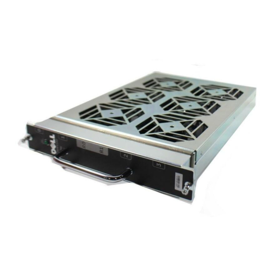
Page 45: Fan Tray
C7004/C150 fixed speed fan tray contains six fans that run at a constant speed. For both types of trays, air flows through the C7004/C150 system toward the fans (right to left) and is exhausted on the fan-side of the chassis. The fan tray is accessible from the front of the chassis. -
Page 46: Installing The Fan Tray
30 seconds, until the fan blades stop rotating, then completely remove the fan tray. Fan Speed C7004/C150 variable speed fan is driven by temperatures measured at the sensor in the fan tray alone. The sensor is located on the fan tray controller located in the fan tray. -
Page 47: Removing And Replacing Components
Removing and Replacing an RPM on page 49 When a component fails, the C7004/C150 System system triggers an alarm LED (located on the active RPM), disables or changes component Status LEDs, and sends events to the SNMP trap and show alarms table (if this feature is configured). -
Page 48: Removing And Replacing Power Supply Units
SNMP trap. If you are operating your C7004/C150 chassis with a redundant power supply, you can install, remove, or replace a power supply without affecting system operation. If you are operating your C7004/C150 system with only one power supply, you must completely power off the system to replace a power supply. -
Page 49: Removing And Replacing A Line Card
Blanks are required to control airflow and electromagnetic interference. You can add, replace, or remove C7004/C150 line cards without interrupting the system power or system operations. To remove and replace C7004/C150 line cards:... - Page 50 NOTE: The C7004/C150 requires at least one RPM to operate. The chassis powers down if you remove the only RPM. To remove and replace a C7004/C150 RPM: Step Task Unplug any network interface cables connected to the RPM. Extend the left and right card levers by first pressing gently down on the thumb tabs (see...
-
Page 51: System Boot
(CLI) prompt, Force10> The RPM cards in the C7004/C150 system use a Compact Flash Card (external flash memory card) to store and retrieve boot and system images. This is the default storage area for the boot files and the startup configuration file. - Page 52 Command Purpose • Enter help or? to display a list of available commands and syntax. help • Enter syntax help to display syntax information and variable descriptions. boot change {primary | If your configuration displays no pre-configured operating system boot parameters, use the boot change command to edit appropriate fields.
- Page 53 Command Purpose (continued) This command displays the current operating system boot configuration show bootvar parameters. BOOT_USER # show bootvar PRIMARY OPERATING SYSTEM BOOT PARAMETERS: ======================================== boot device : flash file name : /FTOS-CB-1.1.x.y.bin SECONDARY OPERATING SYSTEM BOOT PARAMETERS: ========================================== No Operating System boot parameters specified! This command displays information about the current boot ROM.
- Page 54 Do not press break control sequence at any time during the boot/ reboot process. Doing so causes the boot process to terminate. Refer to the Dell Networking OS Command Line Interface Reference for BOOT_USER mode commands and commands for run-time modes.
-
Page 55: The Compact Flash Card
40-character file name length, up to a 180-character local file path length, and up to a 256-character remote file path length. NOTE: Use only a Dell Networking Compact Flash card in your C7004/C150 System. Additional cards can be purchased from Dell Networking. -
Page 56: Formatting The Compact Flash Card
New Compact Flash cards must be formatted in the C7004/C150 before use. Flash cards used on systems other than the C7004/C150, as well as cards formatted on PCs, must be reformatted in the C7004/C150 flash slot before they can be used. Formatting erases all information stored on the flash card. -
Page 57: Alarms
SNMP trap. In the C7004/C150 system, alarms are logged for each occurrence, but the system may not send an event log for multiple occurrences. For example, whenever a module exceeds the shutdown threshold, the module shuts down. -
Page 58: Ac Power Supplies And Alarms
During system boot, if a redundant power supply is removed or fails, Dell Networking OS generates a minor alarm message. If only two power supplies are installed and one of them fails, Dell Networking OS generates an alarm and an SNMP trap (if configured), and lights the RPM alarm LED and power supply LED. -
Page 59: B System Specifications
System Specifications This appendix contains the following major sections: • Physical Design • System Power Specifications on page 62 • Component Power Requirements on page 62 • Agency Compliance on page 63 Physical Design NOTE: See Figure B-1 Figure B-2 on page 61 for the data used for the physical dimensions. - Page 60 Figure B-1. Chassis Dimensions Length/Width 1 7 . 5 i n c h e 1 5 . 7 i n c h e System Specifications...
- Page 61 Figure B-2. Chassis Dimensions Depth i n c h e 1 5 . 5 System Specifications...
-
Page 62: Component Power Requirements
System Power Specifications Table B-2. Power Supply 1600W-AC Parameter C7004/C150 Specifications Nominal input voltage 100-240 V 50/60 Hz Maximum AC Power Supply Input Current 14 A @ 100 V per AC Power Supply (Based on 1200 W output for 100/120 V and... -
Page 63: Agency Compliance
Properly shielded and grounded cables and connectors must be used in order to meet FCC emission limits. Dell Networking is not responsible for any radio or television interference caused by using other than recommended cables and connectors or by unauthorized changes or modifications in the equipment. - Page 64 (VCCI). If this equipment is used in a domestic environment, radio disturbance may arise. When such trouble occurs, the user may be required to take corrective actions. WARNING: AC Power cords are for use with Dell Networking equipment only, do not use Dell Networking AC Power cords with any unauthorized hardware.
-
Page 65: Safety Standards And Compliance Agency Certifications
Networking encourages owners of information technology (IT) equipment to responsibly recycle their equipment when it is no longer needed. Dell Networking offers a variety of product return programs and services in several countries to assist equipment owners in recycling their IT products. - Page 66 EEE on the environment and human health due to the potential presence of hazardous substances in EEE. Dell Networking products, which fall within the scope of the WEEE, are labeled with the crossed-out wheelie-bin symbol, as shown above, as required by WEEE.
-
Page 67: Contacting Technical Support
Contacting Technical Support The iSupport Website iSupport provides a range of documents and tools to assist you with effectively using Dell Networking equipment and mitigating the impact of network outages. Through iSupport you can obtain technical information regarding Dell Networking products, access to software upgrades and patches, and open and manage your Technical Assistance Center (TAC) cases. -
Page 68: Locating Serial Numbers
• Using the Create Service Request form on the iSupport page (see Contacting the Technical Assistance Center on page 67). • Contacting Dell Networking directly by E-mail or by phone (see Contacting the Technical Assistance Center on page 67). Provide the following information when using E-mail or phone: •... - Page 69 Step Task When returning an RMA component, follow the packing and shipping directions in the Return Instructions document that accompanies the replacement component. Alternatively, contact your TAC representative for a replacement copy. Generally, you are instructed to return the RMA component in the original packaging material provided with the replacement, and to label the package with the RMA number.
- Page 70 Contacting Technical Support...
- Page 72 Printed in the U.S.A. w w w. d e l l . c o m | s u p p o r t . d e l l . c o m...