Table of Contents
Advertisement
Quick Links
INSTALLATION MANUAL
AIR
CONDITIONER
Please read this installation manual completely before installing the product.
Installation work must be performed in accordance with the national wiring
standards by authorized personnel only.
Please retain this installation manual for future reference after reading it
thoroughly.
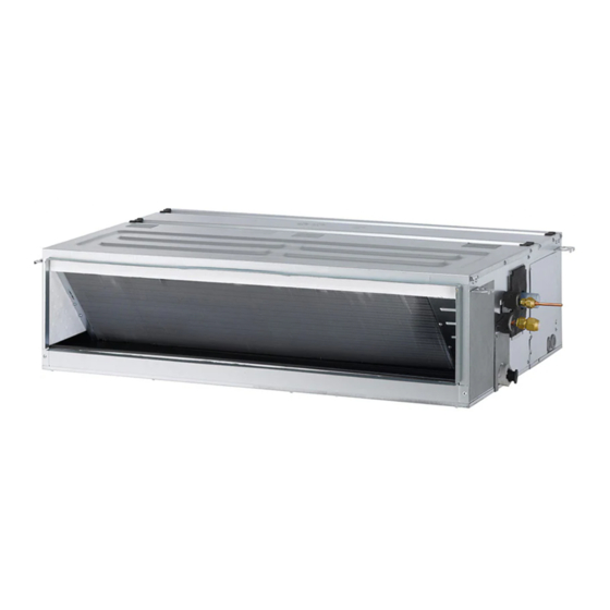
Ceiling Concealed Duct
P/NO : MFL67939906
Copyright © 2014 - 2018 LG Electronics Inc. All Rights Reserved.
www.lg.com
Advertisement
Table of Contents

Related Manuals for LG AB-Q24GM1A2


Summary of Contents for LG AB-Q24GM1A2
- Page 1 Installation work must be performed in accordance with the national wiring standards by authorized personnel only. Please retain this installation manual for future reference after reading it thoroughly. Ceiling Concealed Duct www.lg.com P/NO : MFL67939906 Copyright © 2014 - 2018 LG Electronics Inc. All Rights Reserved.
- Page 2 TIPS FOR SAVING ENERGY TIPS FOR SAVING ENERGY Here are some tips that will help you minimize the power consumption when you use the air conditioner. You can use your air conditioner more efficiently by referring to the instructions below: •...
-
Page 3: Important Safety Instructions
SAFETY PRECAUTIONS IMPORTANT SAFETY INSTRUCTIONS READ ALL INSTRUCTIONS BEFORE USING THE APPLIANCE. Always comply with the following precautions to avoid dangerous situations and ensure peak performance of your product WARNING It can result in serious injury or death when the directions are ignored CAUTION It can result in minor injury or product damage when the directions are ignored WARNING... - Page 4 SAFETY PRECAUTIONS • Do not modify or extend the power cord randomly. - Otherwise, it may cause a fire or electrical shock. • Take care so that the power cord may not be pulled during operation. - Otherwise, it may cause a fire or electrical shock.
-
Page 5: Table Of Contents
TABLE OF CONTENTS TABLE OF CONTENTS TIPS FOR SAVING ENERGY IMPORTANT SAFETY INSTRUCTIONS INTRODUCTION Features INSTALLATION OF INDOOR Selection of the best location Ceiling dimension and hanging bolt location Wiring Connection Indoor Unit Drain Piping Drain test Heat insulation REMOTE CONTROLLER INSTALLATION Group Control OPTIONAL OPERATION Installer Setting -Test Run Mode... -
Page 6: Introduction
INTRODUCTION INTRODUCTION Features Air inlet vents Air outlet vents Remote SPEED Controller TEMP OPER MODE Clamp Washer for Insulation for Name hanging bracket (Tie Wrap) fitting Other Quantity 8 EA 4 EA 1 set • Owner’s manual • Installation manual Shape for gas pipe for liquid pipe... -
Page 7: Installation Of Indoor
INSTALLATION OF INDOOR INSTALLATION OF INDOOR Selection of the best location Ceiling dimension and hanging bolt location Install the air conditioner in the location that satisfies the following conditions. Install the unit above the ceiling correctly. - The place shall easily bear a load exceeding four times the indoor unit’s weight. - Page 8 INSTALLATION OF INDOOR Select and mark the position for fix- CASE 2 ing bolts - Install the unit leaning to a drainage hole side - Drill the hole for set anchor on the face of as a figure for easy water drainage. ceiling.
- Page 9 INSTALLATION OF INDOOR - Upward routing not allowed CAUTION • Install declination of the indoor unit is very important for the drain of the duct type air conditioner. • Minimum thickness of the insulation for the connecting pipe shall be 5 mm. •...
-
Page 10: Wiring Connection
INSTALLATION OF INDOOR Wiring Connection CAUTION • Open the control box cover and connect the The Power cord connected to the unit Remote controller wiring and Indoor power should be selected according to the fol- wires. lowing specifications. • Remove the control box cover for electrical Precautions when laying power wiring connection between the indoor and outdoor Use round pressure terminals for connec-... -
Page 11: Indoor Unit Drain Piping
INSTALLATION OF INDOOR Indoor Unit Drain Piping Drain test - Drain piping must have down-slope (1/50 to - Connect the main drain pipe to the exterior 1/100): be sure not to provide up-and-down and leave it provisionally until the test comes slope to prevent reversal flow. -
Page 12: Heat Insulation
INSTALLATION OF INDOOR Heat insulation Use the heat insulation material for the re- frigerant piping which has an excellent heat-resistance (over 120 °C). Precautions in high humidity circumstance: This air conditioner has been tested ac- cording to the "KS Standard Conditions with Mist"... -
Page 13: Remote Controller Installation
REMOTE CONTROLLER INSTALLATION REMOTE CONTROLLER INSTALLATION Please fix tightly using provided screw Can set up Wired remote controller cable after placing remote controller setup board into three directions. on the place where you like to setup. - Setup direction: the surface of wall recla- - Please set it up not to bend because poor mation, upper, right setup could take place if setup board... -
Page 14: Group Control
REMOTE CONTROLLER INSTALLATION CAUTION Please connect indoor unit and remote controller using connection cable. When installing the wired remote controller, do not bury it in the wall. (It can cause dam- Please check if connector age in the temperature sensor.) is normally connected. - Page 15 REMOTE CONTROLLER INSTALLATION - For ceiling type cassette and duct When installing more than 2 wired remote product group, change the switch setting controllers to one air conditioner, please of the indoor PCB. connect as the right picture. - When installing more than 2 units of wired remote controller to one air - No.
-
Page 16: Optional Operation
OPTIONAL OPERATION OPTIONAL OPERATION Installer Setting -Test Run Mode After installing the product, you must run a Test Run mode. For details related to this operation, refer to the product manual. OPER When pressing the button and MODE button simultaneously for more than 3 seconds, the system will be entered into the installer setting mode. -
Page 17: Installer Setting - Setting Address Of Central Control
OPTIONAL OPERATION Installer Setting - Setting Address of Central Control It's the function to use for connecting central control. Please refer to central controller manual for the details OPER When pressing the button and MODE button simultaneously for more than 3 seconds, the system will be entered into the installer setting mode. -
Page 18: Installer Setting -Thermistor
OPTIONAL OPERATION Installer Setting -Thermistor This is the function to select the temperature sensor to judge the room temperature. OPER When pressing the button and MODE button simultaneously for more than 3 seconds, the system will be entered into the installer setting mode. - After entering into the installer setting mode, select the thermistor sensor OPER... -
Page 19: Installer Setting-Remote Controller Master/Slave Setup
OPTIONAL OPERATION Installer Setting-Remote Controller Master/Slave Setup It is a function for settings in group control, or 2-remote controller control. OPER When pressing the button and MODE button simultaneously for more than 3 seconds, the system will be entered into the installer setting mode. -
Page 20: Installer Setting-Celsius / Fahrenheit Switching
OPTIONAL OPERATION Installer Setting-Celsius / Fahrenheit Switching This function is used for switching the display between Celsius and Fahrenheit. (Optimized only for U.S.A) OPER When pressing the button and MODE button simultaneously for more than 3 seconds, the system will be entered into the installer setting mode. -
Page 21: Installer Setting -E.s.p
OPTIONAL OPERATION Installer Setting -E.S.P. This is the function that decides the strength of the wind for each wind level and because this function is to make the installation easier. - If you set ESP incorrectly, the air conditioner may malfunction. - This setting must be carried out by a certificated-technician. -
Page 22: Installer Setting - Static Pressure Step Setting
OPTIONAL OPERATION Installer Setting - Static Pressure Step Setting This function is applied to only duct type. Setting this in other cases will cause malfunction. This function is only available on some products. This is the function that static pressure of the product is divided in 11 steps for setting. OPER When pressing the button and... - Page 23 OPTIONAL OPERATION [Table. 1] Static Pressure[mmAq(Pa)] 2(20) 2.5(25) 3(29) 4(39) 6(59) 8(78) 10(98) 12(118) 13(127) 14(137) 15(147) Model Step CMM Setting Value 32:01 32:02 32:03 32:04 32:05 32:06 32:07 32:08 32:09 32:10 32:11 HIGH 16.5 ABNQ18GM1A2 14.5 Static Pressure[mmAq(Pa)] 2(20) 2.5(25) 3(29) 4(39) 6(59) 8(78) 10(98) 12(118) 13(127) 14(137) 15(147) Model Step CMM Setting Value...
- Page 24 OPTIONAL OPERATION Static Pressure [mmAq(Pa)] 4(40) 5(50) 6(59) 7(69) 8(78) 9(88) 10(98) 11(108)12(118)13(127)14(137) Model Step CMM Setting Value 32:01 32:02 32:03 32:04 32:05 32:06 32:07 32:08 32:09 32:10 32:11 HIGH ABNQ54GM3A2 NOTE 1. Be sure to set the value refering table 1. Unexpected set value will cause mal-function. 2.
-
Page 25: Dip Switch Setting
DIP SWITCH SETTING DIP SWITCH SETTING Indoor PCB Indoor PCB Indoor PCB Function Description Setting Off Setting On Default Selection of Master or Group Control Master Slave Slave Wired/Wireless remote Dry Contact Selection of Dry Contact controller Auto Mode Mode Selection of Manual or Auto operation Mode Continuous operation...