Table of Contents
Advertisement
Quick Links
Advertisement
Table of Contents

Related Manuals for Acer Aspire 5350


Summary of Contents for Acer Aspire 5350
- Page 1 Aspire 5750/5750G SERVICEGUIDE...
-
Page 2: Revision History
Copyright Copyright © 2010 by Acer Incorporated. All rights reserved. No part of this publication may be reproduced, transmitted, transcribed, stored in a retrieval system, or translated into any language or computer language, in any form or by any means, electronic, mechanical, magnetic, optical, chemical, manual or otherwise, without the prior written permission of Acer Incorporated. - Page 3 Conventions The following conventions are used in this manual: WARNING: Indicates a potential for personal injury. CAUTION: Indicates a potential loss of data or damage to equipment. IMPORTANT: Indicates information that is important to know for the proper completion of a procedure, choice of an option, or completing a task.
-
Page 4: General Information
Acer-authorized Service Providers: Your Acer office may have a different part number code than those given in the FRU list in this service guide. The list provided by your regional Acer office must be used to order FRU parts... -
Page 5: Table Of Contents
CHAPTER 1 Hardware Specifications Features ..........1-5 Operating System . - Page 6 LAN Interface........1-27 Keyboard .
- Page 7 Remove HDD/BIOS Password Utilities..... 2-18 Removing BIOS Passwords ......2-20 Miscellaneous Tools .
- Page 8 Bluetooth Module Installation ......3-33 RTC Battery Removal ....... .3-34 RTC Battery Installation .
- Page 9 USB Failure ........4-13 Wireless Function Failure .
- Page 10 CHAPTER 7 Model Definition and Configuration Aspire 5750......... . 7-3 Aspire 5750G .
- Page 11 CHAPTER Hardware Specifications...
- Page 12 Features ..........1-5 Operating System .
- Page 13 LED 15.6”......... .1-32 LCD Inverter (not available with this model) .
-
Page 15: Features
System Memory Dual-channel DDR3 SDRAM support: Up to 4 GB of DDR3 system memory, upgradable to 8 GB using two soDIMM modules Display 15.6" HD 1366 x 768 resolution, high-brightness (200-nit) Acer CineCrystal™ LED-backlit TFT LCD Mercury-free, environment-friendly 16:9 aspect ratio Hardware Specifications and Configurations ®... -
Page 16: Privacy Control
Privacy Control BIOS user, supervisor, HDD passwords Kensington lock slot Storage Subsystem Hard disk drive: 250/320/500/640/750 GB or larger Multi-in-1 card reader, supporting: Secure Digital™ (SD) Card, MultiMediaCard™ (MMC), Memory Stick PRO™ (MS PRO), xD-Picture Card™ (xD) Graphics Dual independent display support 16.7 million colors External resolution / refresh rates: ®... -
Page 17: Audio Subsystem
Write: 24X CD-R, 16X CD-RW, 8X DVD-R, 8X DVD+R, 4X DVD-R DL, 4X DVD+R DL, 6X DVD-RW, 8X DVD+RW, 5X DVD-RAM Communication Webcam Acer Video Conference, featuring: Acer Crystal Eye webcam with 1280 x 1024 resolution WLAN Acer InviLink™ Nplify™ 802.11b/g/n Wi-Fi CERTIFIED™ Acer InviLink™ 802.11b/g Wi-Fi CERTIFIED™ Supporting Acer SignalUp™ wireless technology WPAN ®... -
Page 18: Dimension And Weight
Two USB 2.0 ports ® HDMI port with HDCP support External display (VGA) port iPhone-compatible Headphone/speaker jack, supporting 3.5 mm headset with built-in microphone for Acer smart handhelds Microphone-in jack Ethernet (RJ-45) port DC-in jack for AC adapter ® Hardware Specifications and Configurations... -
Page 19: Special Keys And Controls
Special Keys and Controls Keyboard 103-/104-/107-key Acer FineTip keyboard with independent standard numeric keypad, international language support Touchpad Multi-gesture touchpad, supporting two-finger scroll, pinch, rotate, flip Media keys Media control keys (printed on keyboard): play/pause, stop, previous, next, volume up,... -
Page 20: Software
Acer Crystal Eye ® Microsoft Silverlight™ Skype™ Windows Live™ Essentials Web links and utilities Acer Accessory Store (Belgium, France, Germany, Italy, Netherlands, Spain, Sweden, UK only) Acer Identity Card Acer Registration Acer Updater ® eBay shortcut 2009 (Canada, France, Germany, Italy, Mexico, Spain, UK, US only) -
Page 21: Notebook Tour
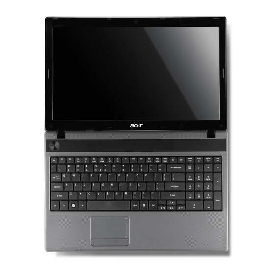
Notebook Tour Top View Figure 1-1. Top View Table 1-1. Top View Icon Integrated webcam Display screen Power button / indicator Hardware Specifications and Configurations Item Web camera for video communication (only for certain models). Also called Liquid-Crystal Display (LCD), displays computer output (Configuration may vary by models). - Page 22 Table 1-1. Top View (Continued) Icon Keyboard Touchpad HDD indicator Communication indicator Power indicator Battery indicator Click buttons (left and right) Microphone 1-12 Item For entering data into your computer. Touch-sensitive pointing device which functions like a computer mouse. Indicates when the hard disk drive is active. Indicates the computer’s wireless connectivity device status.
-
Page 23: Closed Front View
Closed Front View Figure 1-2. Closed Front View Table 1-2. Closed Front View Icon Multi-in-1 card reader HDD indicator Communication indicator Power indicator Battery indicator NOTE: The front panel indicators are visible even when the computer cover is closed. Hardware Specifications and Configurations Item Accepts Secure Digital (SD), MultiMediaCard (MMC), Memory Stick PRO (MS PRO), xD-Picture... -
Page 24: Left View
Connects to USB 2.0 devices (e.g., USB mouse, USB camera). Accepts inputs from external microphones. Connects to audio devices (e.g., speakers, headphones). NOTE: Supports compatible 3.5 mm headsets with built-in microphone (e.g. Acer smart handheld headsets). Hardware Specifications and Configurations Description... -
Page 25: Right View
Right View Figure 1-4. Right View Table 1-4. Right View Icon USB 2.0 ports USB2.0/3.0* port Optical drive Optical drive access indicator Optical drive eject button Emergency eject hole Kensington lock slot Hardware Specifications and Configurations 4 5 6 Item Connect to USB 2.0 devices (e.g., USB mouse, USB camera). -
Page 26: Base View
Base View Figure 1-5. Base View Table 1-5. Base View Icon Battery bay Battery release latch/ lock Memory compartment Hard disk bay 1-16 Item Houses the computer's battery pack. Releases the battery for removal. Insert a suitable tool into the latch and slide to release. -
Page 27: Touchpad Basics
Touchpad Basics Figure 1-6. Touchpad Move finger across the Touchpad (1) to move the cursor. Press the left (2) and right (3) buttons located beneath the Touchpad to perform selection and execution functions. These two buttons are the equivalent of the left and right buttons on a mouse. -
Page 28: Using The Keyboard
Using the Keyboard Figure 1-7. Keyboard Lock Keys The keyboard has three lock keys which can be toggled on and off. (Table 1-7) Table 1-7. Keyboard Lock Keys Lock key Caps Lock When Caps Lock is on, all alphabetic characters typed are in uppercase. Num Lock When Num Lock is on, the embedded keypad is in numeric mode. -
Page 29: Windows Keys
Windows Keys The keyboard has two keys that perform Windows-specific functions. Windows Logo key Application key Table 1-9. Windows Keys Windows Logo Pressed alone, this key has the same effect as clicking on the Windows Start button; it launches the Start menu. It can also be used with other keys to provide a variety of functions. -
Page 30: Hotkeys
Hotkeys Hotkeys or key combinations can be used to access most of the computer's controls like screen brightness and volume output. Figure 1-8. Keyboard Hotkeys To activate hotkeys, press and hold the <Fn> key before pressing the other key in the hotkey combination. - Page 31 Table 1-10. Keyboard Hotkeys (Continued) Hotkey Icon <Fn> + < > <Fn> + < > <Fn> + < > <Fn> + < > <Fn> + <Home> <Fn> + <Pg Up> <Fn> + <Pg Dn> <Fn> + <End> Hardware Specifications and Configurations Function Brightness up Increases the screen brightness.
-
Page 32: System Block Diagram
System Block Diagram Figure 1-9. System Block Diagram 1-22 Hardware Specifications and Configurations... -
Page 33: Specification Tables
Specification Tables Computer specifications Item Dimensions Length Width Height (front to rear) Weight (equipped with optical drive, flash drive, and battery) Input power Operating voltage Operating current Temperature Operating (not writing to optical disc) Operating (writing to optical disc) Nonoperating Relative humidity Operating Nonoperating... -
Page 34: System Board Major Chips
System Board Major Chips Item Core logic Intel Huron Platform Intel NVIDIA N12P-GS/N12P-GV Broadcom BCM57785 GbE Controller USB 2.0 3 Port USB2.0 (1 port is USB3.0 for option) Super I/O controller Bluetooth BT3.0 Broadcom BCM2070, Atheros BU12 Wireless Atheros HB95/HB97, Liteon HB97 PCMCIA Audio codec Realtek ALC271X-GR... -
Page 35: Cpu Fan True Value Table
CPU Fan True Value Table (Tj=105) CPU Temperature Throttling 50%: On= 95 °C; OFF=80 °C OS shut down at 100 °C; H/W shut down at 90 °C CPU Fan True Value Table (Tj=85) CPU Temp Throttling 50%: On= 85 °C; OFF=72 °C OS shut down at 104 °C;... -
Page 36: Memory Combinations
Memory Combinations Slot 1 (MB) 1024 1024 1024 1024 2048 2048 2048 2048 4096 4096 4096 4096 Video Interface Item Chipset Package Interface Compatibility Sampling rate 1-26 Slot 2 (MB) 1024 2048 4096 1024 2048 4096 1024 2048 4096 1024 2048 4096 Specification... -
Page 37: Bios
DMI utility for BIOS serial number configurable/asset tag Support PXE Support WinFlash Wake on LAN from S3 Wake on LAN from S5 in AC mode System information Refer to Acer BIOS specification. Specification Broadcom BCM57785 RJ45 RJ45 at the left side Supports 10/100/1000... -
Page 38: Hard Disk Drive (Avl Components)
Hard Disk Drive (AVL components) Item Vendor & Model HTS545025B9A Name MK2565GSX ST9250315AS Capacity (GB) 250GB Bytes per sector 512 BYTE Data heads Drive Format Disks Spindle speed 5400RPM (RPM) Performance Specifications Buffer size Interface SATA Fast data transfer 3.0Gbits/s rate (Mbits / sec, max) Media data transfer... - Page 39 Item Hard Disk Drive (continued) Data heads Drive Format Disks Spindle speed 5400RPM (RPM) Performance Specifications Buffer size Interface SATA Fast data transfer 3.0Gbits/s rate (Mbits / sec, max) Media data transfer 97Mbytes/s rate 1363.1Mbits/s (Mbytes/sec max) 996Mbits/s DC Power Requirements Voltage tolerance Item Vendor &...
-
Page 40: Super-Multi Drive
Item Hard Disk Drive (continued) Media data transfer 97Mbytes/s rate (Mbytes/sec max) DC Power Requirements Voltage tolerance Super-Multi Drive Item Vendor & Model name Performance Specification Transfer rate (KB/sec) Buffer Memory Interface Applicable disc format Loading mechanism Power Requirement Input Voltage 1-30 Specification 97Mbytes/s... - Page 41 BD Drive Items Vendor & Model PLDS BD COMBO DRIVE TRAY DL DS-6E2SH LF / HLDS BD name COMBO 12.7mm Tray DL CT21N / Pioneer BD COMBO DRIVE TRAY DL BDC-TD03RS / Panasonic BD COMBO DRIVE TRAY DL UJ141ALAA-A / HLDS BD COMBO DRIVE TRAY DL CT30N / Panasonic BD COMBO DRIVE TRAY DL UJ240ABAA-A / Panasonic BD COMBO DRIVE TRAY DL UJ240AFAA-B Performance...
-
Page 42: Led 15.6
LED 15.6” Item Vendor/Model name Screen Diagonal (mm) Active Area (mm) Display resolution (pixels) Pixel Pitch (mm) Typical White Luminance (cd/m also called Brightness Contrast Ratio Response Time (Optical Rise Time/Fall Time) msec Typical Power Consumption (watt) Weight (without inverter) Physical Size (mm) Electrical Interface Viewing Angle (degree) -
Page 43: Display Supported Resolution (Lcd Supported Resolution)
Display Supported Resolution (LCD Supported Resolution) Resolution 800x600p/60Hz 16:9 1024x768p/60Hz 16:9 1280x600/60Hz 16:9 1280x720/60Hz 16:9 1280x768/60Hz 16:9 1360x768/60Hz 16:9 1366x768/60Hz 16:9 Graphics Controller Item VGA Chip Supports Display Supported Resolution (GPU Supported Resolution) Resolution 800x600p/60Hz 16:9 1024x768p/60Hz 16:9 1280x600/60Hz 16:9 1280x720/60Hz 16:9 1280x768/60Hz 16:9 1360x768/60Hz 16:9... -
Page 44: Bluetooth Module
Item Bluetooth Interface (continued) Connector type Supported protocol Bluetooth Module Item Controller Features Camera Item Vendor and Model Type Mini Card Item Number supported Features 3G Card Item Features 1-34 Specification JST SM06B-XSRK-ETB A2DP / AVCTP / AVRCP / BIP / BPP / DUN / Fax / FTP / GAVDP / HCRP / Headset / Hands Free / HID / OPP / PAN / SDAP / Serial / SYNC Specification... -
Page 45: Audio Codec And Amplifier
Audio Codec and Amplifier Item Audio Controller Features Amplifier Features Audio Interface Item Audio Controller Audio onboard or optional Mono or Stereo Resolution Compatibility Sampling rate Internal microphone Internal speaker/quantity Hardware Specifications and Configurations Specification Audio codec: Realtek ALC271X-GR Two stereo DAC support 16/20/24-bit PCM for two independent playback (multiple streaming) Two stereo ADC supports 16/20/24-bit PCM format for two independent recording... -
Page 46: Wireless Module 802.11B/G/N
Wireless Module 802.11b/g/n Item Chipset Atheros HB95/HB97 Data throughput Protocol Interface Battery Item Vendor & Model name Battery Type Pack capacity Number of battery cell Package configuration Item Vendor & Model name Battery Type Pack capacity Number of battery cell Package configuration Item Vendor &... -
Page 47: Usb Port
USB Port Item USB compliance level Protocol Number of USB port(s) Location Output Current HDMI Port Item Compliance level Data thoroughput Number of HDMI port(s) Location AC Adapter Item Input rating Maximum input AC current Inrush current Efficiency Hardware Specifications and Configurations Specification USB2.0/ USB3.0 EHCI... -
Page 48: System Power Management
System Power Management Item Mech. Off (G3) Soft Off (G2/S5) Working (G0/S0) Suspend to RAM (S3) Save to Disk (S4) Card Reader Item Chipset Package Maximum supported size Features 1-38 Specification Al devices in the system are turned off completely. OS initiated shutdown. -
Page 49: System Led Indicator
System LED Indicator Item Lock System state HDD access state Wireless state Power button backlight Battery state System DMA Specification Legacy Mode DMA0 DMA1 DMA2 DMA3 DMA4 DMA5 DMA6 DMA7 *ExpressCard controller can use DMA 1, 2, or 5. Hardware Specifications and Configurations Specification Blue color solid on: System on Blue color and amber color off: System off... -
Page 50: System Interrupt Specification
System Interrupt Specification Hardware IRQ IRQ0 IRQ1 IRQ8 IRQ9 IRQ10 IRQ12 IRQ13 IRQ16 IRQ17 IRQ19 IRQ22 IRQ23 1-40 System Function System timer Standard PS/2 Keyboard System CMOS/real-time clock Broadcom xD Picture Card Host Controller Intel 6 Series/C200 Series Chipset Family SMBus controller -1C22 Synaptics PS/2 TouchPad Numeric data processor... -
Page 51: System Io Address Map
System IO Address Map I/O address (hex) 000 - 01F 020 - 02D 02E - 02F 030 - 03D 040 - 043 04E - 04F 050 - 053 067 - 06C 070 - 077 081 - 091 093 - 09F 0A0 - 0B1 0B2 - 0B3 0B4 - 0BD... -
Page 52: System I/O Address Specifications
System I/O Address Specifications I/O address (hex) System Function (shipping configuration) 220 - 22F 230 - 26D 26E - 26 278 - 27F 280 - 2AB 2A0 - 2A7 2A8 - 2E7 2E8 - 2EF 2F0 - 2F7 2F8 - 2FF 300 - 31F 320 - 36F 370 - 377... - Page 53 CHAPTER System Utilities...
- Page 54 BIOS Setup Utility........2-3 Navigating the BIOS Utility .
-
Page 55: System Utilities
System Utilities BIOS Setup Utility The BIOS Setup Utility is a hardware configuration program built into a computer’s BIOS (Basic Input/Output System). The utility is pre-configured and optimized so most users do not need to run it. If configuration problems occur, the setup utility may need to be run. Refer to when a problem arises. -
Page 56: Bios
BIOS The following is a description of the tabs found on the InsydeH20 BIOS Setup Utility screen: NOTE: NOTE: The screens provided are for reference only. Actual values may differ by model. Information The Information tab shows a summary of computer hardware information. Information Main CPU Type:... - Page 57 Table 2-1. BIOS Information Parameter CPU Type CPU Speed HDD Model Name HDD Serial Number ATAPI Model Name System BIOS Version VGA BIOS Version Serial Number Asset Tag Number Product Name Manufacturer Name UUID System Utilities Description CPU (central processing unit) type and speed of system Speed of the CPU Model name of HDD (hard disk drive) installed on primary IDE master...
-
Page 58: Main
Main The Main tab allows the user to set system time and date, enable or disable boot option and enable or disable recovery. Information Main System Time System Date Total Video Memory: Video Memory: Quiet Boot Network Boot F12 Boot Menu D2D Recovery SATA Mode ... - Page 59 Table 2-2. BIOS Main (Continued) Parameter Network Option to boot system from LAN (local area network) Boot F12 Boot Option to use boot menu during POST Menu Option to use D2D Recovery function Recovery SATA Mode Option to set SATA controller mode System Utilities Description Format/Option...
-
Page 60: Security
Security The Security tab shows parameters that safeguard and protect the computer from unauthorized use. Information Main Supervisor Password Is: User Password Is: HDD Password Is: Set Supervisor Password Set User Password Set HDD Password Power on Password Help ... -
Page 61: Setting A Password
Setting a Password Perform the following to set supervisor password: 1. Use the and keys to highlight the Set Supervisor Password parameter and press Enter. The Set Supervisor Password dialog box appears. Figure 2-4. Set Supervisor Password 2. Type a new password in the Enter New Password field. Passwords are not case sensitive and the length must not exceed 12 characters. -
Page 62: Changing A Password
Set Supervisor Password dialog box appears: Figure 2-5. Set Supervisor Password 2. Type current password in Enter Current Password field and press Enter. 3. Press Enter twice without Password fields. Computer will set Supervisor Password parameter to Clear. 4. Press F10 to save changes and exit the BIOS Setup Utility. Changing a Password 1. - Page 63 Figure 2-7. Setup Notice The password setting is complete after the user presses Enter. If the password entered does not match the current password, the screen shows the Setup Warning dialog. (Figure 2-8) Figure 2-8. Setup Warning: Invalid Password If new password and confirm new password strings do not match, the Setup Warning dialog appears.
-
Page 64: Boot
Boot The Boot tab allows changes to the order of boot devices used to load the operating system. Bootable devices include the: USB diskette drives Onboard hard disk drive DVD drive in the module bay Use and keys to select a device and press F5 or F6 to change the value. Information Main Boot priority order:... -
Page 65: Exit
Exit The Exit tab allows users to save or discard changes and quit the BIOS Setup Utility. Information Main Exit Saving Changes Exit Discard Changes Load Setup Defaults Discard Changes Save Changes Help Exit Figure 2-11. BIOS Exit Table 2-4 describes the parameters in Figure 2-11. -
Page 66: Bios Flash Utilities
BIOS Flash Utilities BIOS Flash memory updates are required for the following conditions: New versions of system programs New features or options Restore a BIOS when it becomes corrupted. Use the Flash utility to update the system BIOS Flash ROM. NOTE: NOTE: If a Crisis Recovery Disc is not available, create one before BIOS Flash utility is... -
Page 67: Dos Flash Utility
DOS Flash Utility Perform the following to use the DOS Flash Utility: 1. Press F2 during boot to enter Setup Menu. 2. Select Boot Menu to modify boot priority order. 3. Move USB HDD to position 1. (Refer to Information Main Boot priority order: HDD:... - Page 68 Figure 2-14. Erasing FLASH ROM Figure 2-15. Updating Flash ROM Blocks 7. Flash is complete when the message, Flash Programming Complete is shown. System will restart automatically when finished. NOTE: NOTE: If AC power is not connected, the following message is shown (Figure 2-16). Plug in the AC power to continue.
-
Page 69: Winflash Utility
WinFlash Utility Perform the following to use the WinFlash Utility: 1. Double-click the WinFlash executable. 2. Click OK to begin the update. A progress screen is shown. (Figure 2-17) Figure 2-17. InsydeFlash 2-17 System Utilities... -
Page 70: Remove Hdd/Bios Password Utilities
Remove HDD/BIOS Password Utilities This section provides details about removing HDD/BIOS passwords. Remove HDD Password as follows: NOTE: NOTE: If the HDD password is incorrectly entered three times, the Password Error Status dialog shown. (Figure 2-18) Figure 2-18. Password Error Status To reset the HDD password, perform the following: 1. - Page 71 <UnlockHD [key code]> with the code noted in the Figure 2-20. Example: UnlockHD 54591747 The command generates a password which can be used for unlocking the HDD. Password: 41499389 Figure 2-21. Unlock Password 5. On original device, enter password (Figure 2-21) in Enter Unlock Password dialog (Figure 2-20).
-
Page 72: Removing Bios Passwords
Removing BIOS Passwords The User and Supervisor passwords can be cleared by shorting the RTC_RST point with a metal instrument. (Figure 2-22) Figure 2-22. CMOS Jumper Cleaning BIOS Passwords To clean the User or Supervisor passwords, perform the following steps: 1. -
Page 73: Using Boot Manager
Using Boot Manager The Boot Manager allows the boot device to be changed without accessing the BIOS. NOTE: NOTE: The F12 Boot Menu option must be set to Enabled in the BIOS Setup Utility’s Main screen. (refer to Main) To use the Boot Manager, perform the following steps: 1. -
Page 74: Miscellaneous Tools
The following examples show the commands and the corresponding output information: Read DMI Information from Memory Input: dmitools /r Output: Manufacturer (Type1, Offset04h): Acer Product Name (Type1, Offset05h): Aspire xxxxx Serial Number (Type1, Offset07h): 01234567890123456789 UUID String (Type1, Offset08h): xxxxxxxx-xxxx-xxxx-xxxx-xxxxxxxxxxxx Asset Tag (Type3, Offset04h): Acet Asstag... -
Page 75: Using The Lan Mac Eeprom Utility
Input: dmitools /wu Write Asset Tag to EEPROM Input: dmitools /wa Acer Asstag NOTE: NOTE: For examples two (2) through five (5), restart the system to to the EEPROM Using the LAN MAC EEPROM Utility 1. Extract and copy the contents of LAN MAC Tools.zip to a bootable USB HDD device. - Page 76 2-24 System Utilities...
- Page 77 CHAPTER Machine Maintenance Procedures...
- Page 78 Introduction ......... 3-5 General Information .
- Page 79 Thermal Module Installation ......3-40 CPU Removal........3-42 CPU Installation .
-
Page 81: Machine Maintenance Procedures
Machine Maintenance Procedures Introduction This chapter contains general information about the notebook, a list of tools needed to perform the required maintenance and step by step procedures on how to remove and install components from the notebook computer. General Information The product previews seen in the following procedures may not represent the final product color or configuration. -
Page 82: Maintenance Flowchart
Maintenance Flowchart The flowchart in Figure 3-1 provides a graphic representation of the module removal and installation sequences. It provides information on what components need to be removed and installed during servicing. Keyboard 3G Card Upper Cover DIMM Module Bluetooth Power Board Module LCD Module... - Page 83 LCD Module LCD Bezel DC-IN Cable CCD Module LCD Panel LCD Panel WLAN & 3G Microphone Brackets Antennas Module Figure 3-2. LCD Module Maintenance Flow Machine Maintenance Procedures...
-
Page 84: Getting Started
Getting Started The flowchart in Figure 3-1 sequence. Observe the order of the sequence to avoid damage to any of the hardware components. Perform the following prior to performing any maintenance procedures: 1. Remove power (A) from the system and peripherals. 2. -
Page 85: Battery Pack Removal
Battery Pack Removal 1. Place computer on flat surface, battery side up. 2. Push battery lock/unlock latch (B) to unlock position. 3. Remove battery pack (A) from lower cover. Figure 3-4. Battery IMPORTANT: Follow local regulations for battery (A, Figure 3-4) disposal. Battery Pack Installation 1. -
Page 86: Dummy Card Removal
Dummy Card Removal 1. Push dummy card (A) in to release it from spring latch. 2. Remove dummy card (A). Figure 3-5. Dummy Card Dummy Card Installation 1. Insert dummy card (A) (Figure 3-5). 2. Push card until spring latch locks. 3-10 Machine Maintenance Procedures... -
Page 87: 3G Card Removal
3G Card Removal Prerequisite: Battery Pack Removal 1. Locate 3G card slot (A) in battery bay (Figure 3-6). Figure 3-6. Lower Cover Overview with Base Door 2. Push 3G card (B) in to release it from spring latch (Figure 3-7). Figure 3-7. -
Page 88: 3G Module Removal
3G Module Removal Prerequisite: Battery Pack Removal 1. Locate module door (B) on lower cover. Refer to 2. Loosen captive screw (A) (Figure 3-8). Figure 3-8. 3G Module Cover Door 3. Remove door from lower cover. 4. Disconnect main (B) and auxiliary (C) antenna cables from module (Figure 3-9). Figure 3-9. -
Page 89: 3G Module Installation
3G Module Installation 1. Insert module into mainboard connector (D). Refer to Figure 3-9. 2. Install and secure screw (A) to mainboard. 3. Install main (B) and auxiliary (C) antenna cables on 3G module. 4. Install 3G module door (B). Refer to Figure 3-6. -
Page 90: Base Door Removal
Base Door Removal Prerequisite: Battery Pack Removal 1. Locate base door (C) on lower cover. Refer to 2. Remove two (2) screws (A) as shown in Figure 3-10. Figure 3-10. Lower Cover Door Screws 3. Remove door from lower cover. Base Door Installation 1. - Page 91 Size Quantity Screw Type M2.5x8.0 3-15 Machine Maintenance Procedures...
-
Page 92: Hdd (Hard Disk Drive) Module Removal
HDD (Hard Disk Drive) Module Removal Prerequisite: Base Door Removal 1. Locate HDD module (A) on lower cover Figure 3-12. Lower Cover Overview with Base Door Removed 2. Slide module away from mainboard connector (A) (Figure 3-13). Figure 3-13. HDD Module 3. -
Page 93: Hdd Module Installation
HDD Module Installation 1. Place module into bay on lower cover. Refer to 2. Connect module to mainboard connector (A). Refer to 3. Install base door. Machine Maintenance Procedures Figure 3-12. Figure 3-13. 3-17... -
Page 94: Hdd Carrier Removal
HDD Carrier Removal Prerequisite: HDD (Hard Disk Drive) Module Removal 1. Remove four (4) screws (A) from the brackets (Figure 3-14). Figure 3-14. HDD Module Brackets 2. Remove brackets (B) and (C) and mylar (D) from HDD. 3. Remove mylar from brackets. HDD Carrier Installation 1. -
Page 95: Odd Module Removal
ODD Module Removal Prerequisite: HDD (Hard Disk Drive) Module Removal 1. Locate ODD module (D) on lower cover. Refer to 2. Remove screw (A) from lower cover. 3. To remove module, push from HDD bay (A) (Figure 3-15). Figure 3-15. ODD Module in Lower Cover 4. -
Page 96: Odd Module Installation
ODD Module Installation 1. Install bezel (C) to module. Refer to 2. Install bracket (B) to module. 3. Install and secure two (2) screws (A). 4. Install module (D) in lower cover. Refer to 5. Install and secure screw (A) to lower cover. 6. -
Page 97: Wlan (Wireless Local Area Network) Module Removal
WLAN (Wireless Local Area Network) Module Removal Prerequisite: Base Door Removal 1. Locate module (B) on lower cover. Refer to 2. Disconnect main (B) and auxiliary (C) antenna cables from module (Figure 3-17). Figure 3-17. WLAN Module NOTE: NOTE: Main (black) antenna connector is close to front of computer. Auxiliary (white) antenna connector is close to ODD module. -
Page 98: Dimm (Dual In-Line Memory Module) Module Removal
DIMM (Dual In-line Memory Module) Module Removal Prerequisite: Base Door Removal 1. Locate module (C) on lower cover. Refer to 2. Push module clips (A) outwards. (Figure 3-18) Figure 3-18. DIMM Module(s) 3. Disconnect module from mainboard connector (B). 4. Repeat steps 2 and 3 for remaining modules. DIMM Module Installation 1. -
Page 99: Keyboard Removal
Keyboard Removal Prerequisite: Battery Pack Removal 1. Locate and unlock six (6) latches above keys, F1, F4, F8, F12, Del, and End (Figure 3-19). Figure 3-19. Keyboard 2. Lift keyboard frame from upper cover, starting from top edge. CAUTION: Keyboard FPC (Flexible Printed Circuit) can be damaged if removed while mainboard connector is locked. -
Page 100: Keyboard Installation
3. Carefully flip keyboard as shown in Figure 3-20. Figure 3-20. Keyboard FPC 4. Remove keyboard FPC (B) from mainboard connector (A). Keyboard Installation 1. Insert keyboard frame flanges (A, Figure 3-21) into upper cover slots. Figure 3-21. Keyboard Frame Flanges 2. -
Page 101: Upper Cover Removal
Upper Cover Removal Prerequisite: Keyboard Removal Base Door Removal 1. Remove six (6) screws (A) from upper cover (Figure 3-22). Figure 3-22. Upper Cover 2. Remove power board FFC (Flat Flexible Cable) (B) from mainboard connector (C). Machine Maintenance Procedures 3-25... - Page 102 3. Turn computer over to show lower cover. 4. Remove five (5) screws (A) from battery bay (Figure 3-23). Figure 3-23. Lower Cover Screws 5. Remove seven (7) screws (B), two (2) screws (C), and one (1) screw (D) from lower cover. 6.
-
Page 103: Upper Cover Installation
8. Remove upper cover from lower cover as shown in Figure 3-25. Figure 3-25. Removing Upper Cover Upper Cover Installation 1. Install and secure upper cover latches on lower cover 2. Turn computer over to show lower cover. 3. Install and secure five (5) screws (A) in battery bay. Refer to 4. -
Page 104: Touchpad Board Ffc Removal
Touchpad Board FFC Removal Prerequisite: Upper Cover Removal 1. Locate touchpad board (A) on upper cover (Figure 3-26). Figure 3-26. Upper Cover Overview 2. Remove touchpad FFC (A) from touchpad board connector (B) (Figure 3-27). Figure 3-27. Touchpad FFC Removal 3. -
Page 105: Touchpad Board Ffc Installation
Touchpad Board FFC Installation 1. Install touchpad FFC (A) to opening in upper cover mylar. Refer to Figure 3-27. 2. Install touchpad FFC (A) to touchpad board connector (B). 3. Install upper cover. 3-29 Machine Maintenance Procedures... -
Page 106: Power Board Removal
Power Board Removal Prerequisite: Upper Cover Removal 1. Locate power board (B) on upper cover. Refer to 2. Remove screw (A) from upper cover (Figure 3-28). Figure 3-28. Power Board Removal 3. Remove power board FFC (B) from opening in upper cover mylar (C). Power Board Installation 1. -
Page 107: Usb Module Removal
USB Module Removal Prerequisite: Upper Cover Removal 1. Locate USB module (C) on lower cover Figure 3-29. Mainboard Overview 2. Remove screw (D) from lower cover (Figure 3-30). Figure 3-30. USB 2.0 Module Machine Maintenance Procedures (Figure 3-29). 3-31... -
Page 108: Usb Module Installation
3. Disconnect module FFC (FPC, Figure 3-31) (A) from module connector (B). Figure 3-31. USB 3.0 Module NOTE: NOTE: USB 3.0 is an optional feature and may not represent the final product. 4. Disconnect module FFC (FPC, Figure 3-31) (A) from mainboard connector (C). 5. -
Page 109: Bluetooth Module Removal
Bluetooth Module Removal Prerequisite: Upper Cover Removal 1. Locate Bluetooth module (B) on upper cover. Refer to 2. Remove module (A) from adhesive strip on upper cover (Figure 3-32). Figure 3-32. Bluetooth Module 3. Disconnect module cable (B) from module (A). Bluetooth Module Installation 1. -
Page 110: Rtc Battery Removal
RTC Battery Removal Prerequisite: Upper Cover Removal 1. Locate RTC battery (B) on mainboard. Refer to 2. Remove battery (B) from mainboard connector (A) (Figure 3-33). Figure 3-33. RTC Battery Removal IMPORTANT: Follow local regulations for battery (Figure 3-33) disposal. RTC Battery Installation 1. -
Page 111: Speaker Module Removal
Speaker Module Removal Prerequisite: Upper Cover Removal 1. Locate speaker modules (D) on upper cover. Refer to 2. Remove two (2) screws (A) (Figure 3-34). Figure 3-34. Speakers 3. Remove speaker cable (C) from mainboard connector (B). 4. Remove speaker modules. Speaker Module Installation 1. -
Page 112: Mainboard Removal
Mainboard Removal Prerequisite: HDD (Hard Disk Drive) Module Removal WLAN (Wireless Local Area Network) Module Removal Speaker Module Removal 1. Locate mainboard (E) on lower cover. Refer to 2. Remove two (2) screws (A) from lower cover (Figure 3-35). Figure 3-35. Mainboard Screws & WLAN Antennas 3. - Page 113 Figure 3-36. Freeing Mainboard Connectors NOTE: NOTE: Connectors on left side of mainboard (i.e. USB 3.0, HDMI, etc.) are set in lower cover slots. Do not force mainboard when removing. 6. Remove mainboard from lower cover by pulling away from left side (A). 7.
-
Page 114: Mainboard Installation
Mainboard Installation 1. Connect DC-IN (B) cable to mainboard connector (A). Refer to 2. Flip mainboard over and align mainboard connectors to left side of lower cover. Refer to Figure 3-36. 3. Install mainboard by sliding left side (A) at a slight angle into slots on left side of lower cover. -
Page 115: Thermal Module Removal
Thermal Module Removal Prerequisite: Mainboard Removal 1. Locate thermal module (A) on mainboard (Figure 3-38). Figure 3-38. Thermal Module Removal 2. Remove module cable (B) from mainboard connector. 3. Remove four (4) screws (C/1 - C/4) and two (2) screws (D/5 - D/6) from mainboard. 4. -
Page 116: Thermal Module Installation
Thermal Module Installation IMPORTANT: Apply suitable thermal grease and make sure all heat pads are in place before replacing module CAUTION: Thermal grease can damage mainboard. Use caution when applying. The following thermal grease types are approved for use: N302 1. - Page 117 3. Align module and heatsink to mainboard screw holes (Figure 3-40). NOTE: NOTE: Keep module level to spread grease evenly. Figure 3-40. Thermal Module Installation 4. Install and secure four (4) screws (C/1 - C/4) and two (2) screws (D/5 - D/6), in numerical order from one (1) to six (6), to mainboard.
-
Page 118: Cpu Removal
CPU Removal Prerequisite: Thermal Module Removal 1. Locate module (A) on mainboard (Figure 3-41). Figure 3-41. CPU in Socket 2. Turn captive screw (B) left 180º to release module. 3. Remove module from socket. CPU Installation 1. Align CPU marker (C) with socket marker (D) and install CPU in socket (Figure 3-41). 2. - Page 119 Figure 3-42. Mainboard Recycling IMPORTANT: Circuit boards >10 cm² must be recycled. Follow local regulations for disposal. 3-43 Machine Maintenance Procedures...
-
Page 120: 3G Board Removal
3G Board Removal Prerequisite: Mainboard Removal 1. Locate 3G board (A) on mainboard (Figure 3-43). Figure 3-43. Lower Cover with 3G Board 2. Remove two (2) screws (A) from lower cover as shown in Figure 3-44. Figure 3-44. 3G Board Removal 3. -
Page 121: 3G Board Installation
3G Board Installation 1. Install 3G board on lower cover. Refer to Figure 3-43. 2. Secure two (2) screws (A) to lower cover. Refer to Figure 3-44. 3. Install mainboard. 3-45 Machine Maintenance Procedures... -
Page 122: Lcd (Liquid Crystal Display) Module Removal
LCD (Liquid Crystal Display) Module Removal Prerequisite: Speaker Module Removal 1. Flip computer over to show lower cover. Refer to 2. Remove WLAN antenna cables (A) from WLAN module connectors (Figure 3-45). Figure 3-45. WLAN Module Cables 3. Remove WLAN antenna cables (A) from guides (B) on lower cover. 4. -
Page 123: Lcd Module Installation
5. Flip computer over to show mainboard. Refer to 6. Remove adhesive tape securing WLAN cable (B) to mainboard and lower cover. 7. Pull WLAN and 3G antenna cables up through upper cover. 8. Remove four (4) screws from LCD module hinges (Figure 3-47). Figure 3-47. - Page 124 9. Install speaker modules. Size Quantity Screw Type M2.5x4.0 3-48 Machine Maintenance Procedures...
-
Page 125: Dc-In Cable Removal
DC-IN Cable Removal Prerequisite: LCD (Liquid Crystal Display) Module Removal 1. Locate DC-IN cable (A) on mainboard (Figure 3-49). Figure 3-49. DC-IN Cable Removal 2. Remove cable from guides on lower cover. 3. Remove cable connector from lower cover. DC-IN Cable Installation 1. -
Page 126: Lcd Bezel Removal
LCD Bezel Removal Prerequisite: LCD (Liquid Crystal Display) Module Removal 1. Locate the LCD Bezel (A) on the LCD module (Figure 3-50) Figure 3-50. LCD Module Overview with Bezel 2. Remove the two (2) mylar covers and two (2) screws (C) from module. (Figure 3-51) Figure 3-51. -
Page 127: Lcd Bezel Installation
3. Starting from the bottom-center of the bezel (Figure 3-52), pry the bezel upwards and away from the panel. Move along the edge until the bezel is completely removed. Figure 3-52. LCD Bezel Removal Size M2.5x4.0 LCD Bezel Installation 1. Locate the bezel hinges (B) on LCD cover (Figure 3-52). 2. -
Page 128: Ccd (Charge-Coupled Device) Module Removal
CCD (Charge-Coupled Device) Module Removal Prerequisite: LCD Bezel Removal 1. Locate CCD module (A) on LCD module cover (Figure 3-53). Figure 3-53. LCD Module Overview without Bezel 2. Remove module cable (G) from module connector (F) as shown in Figure 3-54. Figure 3-54. -
Page 129: Lcd Panel Removal
LCD Panel Removal Prerequisite: CCD (Charge-Coupled Device) Module Removal 1. Locate LCD panel (B) on module cover. Refer to 2. Remove four (4) screws (C) from module cover. 3. Lift adhesive foil tabs (D) covering LVDS cable (E). 4. Remove panel from module cover. 5. -
Page 130: Lcd Brackets Removal
LCD Brackets Removal Prerequisite: LCD Panel Removal 1. Remove six (6) screws (A) from panel. Figure 3-56. LCD Brackets Module 2. Remove brackets (B) from panel. LCD Brackets Installation 1. Install brackets (B) on panel (Figure 3-56). 2. Install and secure six (6) screws (A) to panel. 3. -
Page 131: Wlan And 3G Antenna Removal
WLAN and 3G Antenna Removal Prerequisite: LCD Panel Removal 1. Lift foil tabs (A) covering left WLAN and 3G antennas (B). (Figure 3-57) Figure 3-57. LCD Module Cover without Panel NOTE: NOTE: WLAN antenna cables not shown in image. 2. Remove left WLAN and 3G antennas (B) from cable guides. 3-55 Machine Maintenance Procedures... -
Page 132: Wlan And 3G Antenna Installation
3. Remove EMI (Electromagnetic interference) foam (E) and aluminium foil (F) covering left WLAN and 3G antennas from LCD module cover. (Figure 3-58) Figure 3-58. 3G and WLAN EMI Foam and Aluminium Foil 4. Remove left WLAN and 3G antennas (B) from LCD module cover. 5. -
Page 133: Microphone Module Removal
Microphone Module Removal Prerequisite: LCD Panel Removal 1. Locate module (D) on LCD module cover. Refer to 2. Lift foil tabs (A) covering module cable (B). Figure 3-59. Microphone Module and Cable 3. Lift foil tab covering module. 4. Remove module (C) and cable (B) from LCD module cover. Microphone Module Installation 1. - Page 134 3-58 Machine Maintenance Procedures...
- Page 135 CHAPTER Troubleshooting...
- Page 136 Introduction ......... 4-3 General Information .
-
Page 137: Troubleshooting
The following procedures are a guide for troubleshooting computer problems. The step by step procedures are designed to be performed as described. NOTE: NOTE: The diagnostic tests are intended for Acer products only. Non-Acer products, prototype cards, or modified options can give false errors and invalid system responses. NOTE: NOTE: Do not replace a non-defective FRU. -
Page 138: Power On Issues
Power On Issues If the system does not power on, perform the following: Figure 4-1. Power On Issue Computer Shuts Down Intermittently If the system powers off at intervals, perform the following. 1. Makes sure the power cable is properly connected to the computer and the electrical outlet. -
Page 139: No Display Issues
No Display Issues If the Display does not work, perform the following: Figure 4-2. No Display Issue No POST or Video If the POST or video does not appear, perform the following: 1. Make sure that internal display is selected. Switching between internal and external by pressing Fn+F5. -
Page 140: Abnormal Video
9. Reseat the memory modules. 10. Remove the drives. (refer to 11. If the Issue is still not resolved, refer to Abnormal Video If the video appears abnormal, perform the following: 1. Boot the computer. If permanent vertical/horizontal lines or dark spots appear in the same location, the LCD is faulty and should be replaced. -
Page 141: Lcd Failure
LCD Failure If the LCD fails, perform the following: Figure 4-3. LCD Failure Troubleshooting... -
Page 142: Keyboard Failure
Keyboard Failure If the Keyboard fails, perform the following: Figure 4-4. Keyboard Failure Troubleshooting... -
Page 143: Touchpad Failure
Touchpad Failure If the Touchpad fails, perform the following: Figure 4-5. Touchpad Failure Troubleshooting... -
Page 144: Internal Speaker Failure
Internal Speaker Failure If internal Speakers fail, perform the following: Figure 4-6. Internal Speaker Failure Sound Problems Perform the following: 1. Boot the computer. 2. Navigate to Start Control Panel Manager. Check the Device Manager to determine that: The device is properly installed ... - Page 145 5. Make sure that all volume controls are set mid range: Click the volume icon on the taskbar Drag the slider to 50. Confirm that the volume is not muted. Click Mixer to verify that other audio applications are set to 50 and not muted. ...
-
Page 146: Microphone Failure
Microphone Failure If internal or external Microphones fail, perform the following: Figure 4-7. Microphone Failure 1. Check that the microphone is enabled. Navigate to Start and Sound Sound and select the Recording tab. 2. Right click on the Recording tab and select Show Disabled Devices (clear by default). -
Page 147: Usb Failure
USB Failure If the USB fails, perform the following: Figure 4-8. USB Failure 4-13 Troubleshooting... -
Page 148: Wireless Function Failure
Wireless Function Failure If the WLAN fails, perform the following: Figure 4-9. Wireless Function Failure 4-14 Troubleshooting... -
Page 149: Bluetooth Failure
Bluetooth Failure If the Bluetooth fails, perform the following: Figure 4-10. Bluetooth Failure 4-15 Troubleshooting... -
Page 150: Card Reader Failure
Card Reader Failure If the Card Reader fails, perform the following: Figure 4-11. Card Reader Failure 4-16 Troubleshooting... -
Page 151: Thermal Unit Failure
Thermal Unit Failure If the Thermal Unit fails, perform the following: Figure 4-12. Thermal Failure 4-17 Troubleshooting... -
Page 152: Other Functions Failure
Other Functions Failure HDD Not Operating Correctly If the HDD fails to operate correctly, perform the following: 1. Disconnect all external devices. 2. Run a complete virus scan using up-to-date software to confirm the computer is virus free. 3. Run the Windows Vista Startup Repair Utility: a. -
Page 153: Odd Failure
ODD Failure If the ODD fails, perform the following: Figure 4-13. ODD Failure ODD Not Operating Correctly If the ODD exhibits any of the following symptoms it may be faulty: Audio CDs do not play when loaded DVDs do not play when loaded Troubleshooting 4-19... - Page 154 Blank discs do not burn correctly DVD or CD play breaks up or jumps Optical drive not found or not active: Not shown in My Computer or the BIOS setup LED does not flash when the computer starts up ...
- Page 155 Double click DVD/CD-ROM drives. Right click DVD drive and click Properties, then click the DVD Region tab. Select the region suitable for the media inserted in the drive. Discs Do Not Burn Properly If discs can not be burned, perform the following: 6.
-
Page 156: Random Loss Of Bios Settings
Drive Read Failure If discs cannot be read when inserted in the drive, perform the following: 1. Remove and clean the failed disc. 2. Retry reading the CD or DVD. Test the drive using other discs. Play a DVD movie ... -
Page 157: Intermittent Problems
1. Remove power from the computer. 2. Visually check FRUs for damage. If any problems are found, replace the FRU. 3. Remove or disconnect all of the following devices: Non-Acer devices Printer, mouse, and other external devices ... - Page 158 5. Determine if the problem has changed. 6. If the problem does not recur, connect the removed devices until failing FRU is found. 7. If the problem remains, replace the following: System board LCD assembly 4-24 Troubleshooting...
-
Page 159: Post Codes
Post Codes The following tables describe the POST codes and descriptions during the POST. Table 4-2. NO_EVICTION_MODE_DEBUG EQU 1 (CommonPlatform\sec\Ia32\SecCore.inc) Phase 0xC2 MTRR setup 0xC3 Enable cache 0xC4 Establish cache tags nf 0xC5 Enter NEM, Place the BSP in No Fill mode, set CR0.CD = 1, CR0.NW = 0. 0xCF Cache Init Finished Table 4-3. - Page 160 Table 4-3. DEBUG_BIOS equ 1 (Chipset\Alviso\MemoryInitAsm\IA32\IMEMORY.INC) (Continued) Phase 0x31 Program DRAM throttling and throttling event registers 0x32 Setup DRAM control register for normal operation and enable 0x33 Enable RCOMP 0x34 Clear DRAM initialization bit in the SB 0x35 Initialization Sequence Completed, program graphic clocks 0x43 Program Thermal Throttling Table 4-4.
- Page 161 Table 4-4. BDS & Specific action: (Continued) Phase 0xB9 Peripheral removable media disable Con 0xBB Peripheral removable media enable 0xE4 Report Status Code here for DXE_ENTRY_POINT once it is available 0xF8 Report that ExitBootServices() has been called re 0xF9 Runtime driver set virtual address map Table 4-5.
- Page 162 Table 4-5. Each PEIM entry point used in 80_PORT (Continued) Phase 0xAF PEI_DXE_IPL Table 4-6. Each Driver entry point used in 80_PORT Phase 0x30 RESERVED 0xB6 DXE_CRC32_SECTION_EXTRACT 0xB8 SCRIPT_SAVE 0xB9 ACPI_S3_SAVE 0xBA SMART_TIMER 0xBB JPEG_DECODER 0xBC PCX_DECODER 0xBE HT_CPU / MP_CPU 0xBF LEGACY_METRONOME 0xC0...
- Page 163 Table 4-6. Each Driver entry point used in 80_PORT (Continued) Phase 0xE8 ISA_BUS 0xE9 ISA_SERIAL 0xED BUS_PCI_UNDI 0xEC PCI_BUS 0xF6 BOOT_PRIORITY 0xF7 FVB_SERVICE 0xF8 ACPI_PLATFORM 0xFB PCI_HOT_PLUG 0xFC DXE_PLATFORM Soft 0xFD PLATFORM_IDE 0x97 e SMBIOS 0x98 MEMORY_SUB_CLASS 0x99 MISC_SUB_CLASS 0x82 CON_PLATFORM 0x83 SAVE_MEMORY_CONFIG...
- Page 164 Table 4-6. Each Driver entry point used in 80_PORT (Continued) Phase 0x6E e USB_BOT 0x6F USB_CBI0 0x74 USB_MOUSE 0xFA SETUP_UTILITY 0x90 FW_BLOCK_SERVICE 0x78 SMM_USB_LEGACY 0x86 GRAPHICS_CONSOLE 0x87 TERMINAL 0x8A DATA_HUB_STD_ERR 0x7C 0x7D PARTITION 0x7E ENGLISH 0x7F FRENCH 0x9E HII_DATABASE 0x9F OEM_SETUP_BROWSER 0x8C OEM_BADGING_SUPPORT...
- Page 165 Table 4-6. Each Driver entry point used in 80_PORT (Continued) Phase 0xB0 JAPANESE 0xB1 DXE_UNICODE_COLLACTION Table 4-7. Each SmmDriver entry point used in 80_PORT 0xD4 0xDE 0xCC 0xD2 0xDF 0xD0 0xCA 0xFE 0xD8 e 0x90 0x91 0x92 0x93 0x94 0x95 0xD3 Troubleshooting POST Code Range...
- Page 166 4-32 Troubleshooting...
- Page 167 CHAPTER Jumper and Connector Locations...
- Page 168 Mainboard ......... . 5-3 USB Board.
-
Page 169: Jumper And Connector Locations
Jumper and Connector Locations Mainboard Figure 5-1. Mainboard Top Table 5-1. Mainboard Top Item Description JLVDS1 LVDS Connector JMIC2 Internal MIC Connector JSPK1 Speaker Connector JSPK2 Speaker Connector JTP1 Touch Pad Broad Connector JKB1 Keyboard Connector JUSB1 USB2.0 Broad Connector JUSB3 USB3.0 Broad Connector Jumper and Connector Locations... - Page 170 Figure 5-2. Mainboard Bottom Table 5-2. Mainboard Bottom Item Description PJP1 DC-IN Connector PJP2 Battery Connector JRJ1 LAN Connector JCRT1 D-SUB Connector JHDMI1 HDMI Connector JUSB5 USB Connector JMIC1 Audio JACK(MIC) JHP1 Audio Combo Jack JFAN1 FAN Connector Item Description JCPU1 CPU Connector JDIMM1/J...
-
Page 171: Usb Board
USB Board Figure 5-3. USB Board Top Figure 5-4. USB Board Bottom Table 5-3. USB Board Item JUSB1 JUSB2 JUSB3 JUSB4 Jumper and Connector Locations Description USB2.0 Connector USB3.0 Connector USB3.0 Broad Connector USB2.0 Broad Connector WLAN EN Connector WLAN EN Switch... -
Page 172: Power Board
Power Board Figure 5-5. Power Board Top Figure 5-6. Power Board Bottom Table 5-4. Power Board Item Switch Button for E0 project Switch Button for S0 project Switch Button for D0 project Speaker Connector To PWR/B FFC To M/B FFC To LID/B FFC Description Jumper and Connector Locations... -
Page 173: Card Reader
Card Reader Figure 5-7. Card Reader Top Figure 5-8. Card Reader Bottom Table 5-5. Power Board Item JSIM1 SIM Card Connector JMINI1 MINI Card Connector J3G1 3G Board Connector Jumper and Connector Locations Description... -
Page 174: Clearing Password Check And Bios Recovery
Clearing Password Check and BIOS Recovery This section provides users with the SOP (standard operating procedure) for clearing the BIOS password check and recovering the BIOS for the Aspire 5750/5750G. Clearing Password Check NOTE: NOTE: The following procedure is only for clearing BIOS Password (Supervisor Password and User Password). - Page 175 6. Plug in AC adapter. 7. Press Power button until BIOS POST is finished 8. Remove conductivity tool from RCT_RST point. 9. Restart the system and press F2 to enter BIOS Utility Setup menu. 10. If no password prompt is shown, BIOS password is cleared. 11.
-
Page 176: Bios Recovery By Crisis Disk
BIOS Recovery by Crisis Disk BIOS Recovery Boot Block The BIOS Recovery Boot Block is a special block of BIOS. It is used to boot up the system with minimum BIOS initialization. Users can enable this feature to restore the BIOS firmware if a previous BIOS flashing process has failed. - Page 177 2. Copy ROM (read-only memory) file, P5WEOX64.fd, to root directory of USB HDD. Make sure that there is no other BIOS file is saved in the same directory. 3. Insert USB HDD into USB port. 4. Press <Fn + ESC> button and hold while plugging in AC power adapter. 5.
- Page 178 5-12 Jumper and Connector Locations...
-
Page 179: Fru (Field Replaceable Unit) List
CHAPTER FRU (Field Replaceable Unit) List... - Page 180 Exploded Diagrams ........6-4 Main Assembly ........6-4 LCD Assembly .
- Page 181 DIFFERENT part number code from those given in the FRU list of this printed Service Guide. Users MUST use the local FRU list provided by the regional Acer office to order FRU parts for repair and service of customer machines.
-
Page 182: Exploded Diagrams
Exploded Diagrams Main Assembly Figure 6-1. Main Assembly Exploded Diagram FRU (Field Replaceable Unit) List... - Page 183 Mainboard AS5750 Intel HM65 LF Intel UMA graphics USB BOARD 2.0 MOUNT W/ FFC CABLE SPEAKER L LOWER CASE FOR W/3G SPEAKER R MIC SET FRU (Field Replaceable Unit) List Description Acer Part No. 60.R9702.001 60.R9702.006 23.R9702.001 60.RCF02.001 MB.R9702.001 55.RFD02.003 23.R9702.003 60.RFD02.001...
-
Page 184: Lcd Assembly
LCD Assembly Figure 6-2. LCD Assembly Exploded Diagram FRU (Field Replaceable Unit) List... - Page 185 LCD BEZEL LED LCD AUO 15.6"W WXGA Glare B156XW02 V2 LF 200nit 8ms 500:1 (power saving) LCD CABLE LCD BRACKET R&L CAMERA 1.3M LCD COVER IMR-BLACK FRU (Field Replaceable Unit) List Acer Part No. 60.R9702.005 LK.15605.010 50.R9702.003 33.R9702.004 57.R9702.001 60.R9702.004...
-
Page 186: Upper Cover
Upper Cover Figure 6-3. Upper Cover Exploded Diagram Table 6-3. Upper Cover Exploded Diagram UPPER CASE IMR-BLACK POWER BOARD TP FFC Description Acer Part No. 60.R9702.001 55.RFD02.001 50.RFD02.003 FRU (Field Replaceable Unit) List... -
Page 187: Lower Cover
Lower Cover Figure 6-4. Lower Cover Exploded Diagram Table 6-4. Lower Cover Exploded Diagram Description LOWER CASE FOR W/3G UNI-LOAD DOOR 3G CARD DOOR FOR W/ 3G FRU (Field Replaceable Unit) List Acer Part No. 60.RFD02.001 60.R9702.003 42.RFD02.001... -
Page 188: Fru List
FRU List Table 6-5. FRU List Category ADAPTER Adapter LITE-ON 65W 19V 1.7x5.5x11 Yellow PA-1650-22AC LV5 LED LF Adapter DELTA 65W 19V 1.7x5.5x11 Yellow ADP-65VH BA, LV5, Low profile LED LF Adapter LITE-ON 65W 19V 1.7x5.5x11 Yellow PA-1650-69AW, LV5, Low profile LED LF Adapter Chicony Power 65W 19V 1.7x5.5x11 Yellow CPA09-A065N1, LV5, low profile LF Adapter DELTA 90W 19V 1.7x5.5x11 Blue... - Page 189 Table 6-5. FRU List (Continued) Category POWER BOARD USB BOARD 3.0 USB BOARD 2.0 MOUNT W/ FFC CABLE FPC BOARD FOR USB 3.0 3G BOARD Foxconn Wirelss LAN Atheros HB95BG (HM) T77H121.10 Foxconn Wireless LAN Atheros HB97 2x2 BGN (HM) Liteon Wireless LAN Atheris HB97 2x2 BGN (HM) WN6603AH Foxconn Wireless LAN Broadcomm 43225 2x2...
- Page 190 Table 6-5. FRU List (Continued) Category 3G CARD Huawei EM770W-Rev2 CABLE BLUE TOOTH CABLE-6PIN 3G CABLE TP FFC POWER CORD US 3 PIN POWER CORD EU 3 PIN POWER CORD AUS 3 PIN POWER CORD UK 3 PIN POWER CORD CHINA 3 PIN POWER CORD SWISS 3 PIN POWER CORD ITALIAN 3 PIN POWER CORD DENMARK 3 PIN...
- Page 191 Table 6-5. FRU List (Continued) Category CASE/COVER/BRACKET ASSEMBLY UPPER CASE IMR-BLACK UPPER CASE IMR-BLUE LOWER CASE FOR W/3G LOWER CASE FOR W/O 3G UNI-LOAD DOOR 3G CARD DOOR FOR W/ 3G 3G CARD DOOR FOR W/O 3G HDD BRACKET H9.5 HDD BRACKET H7 CPU/PROCESSOR CPU Intel Core i3 i3-2310M PGA 2.1G 35W 2/4...
- Page 192 Table 6-5. FRU List (Continued) Category ODD BRACKET ODD BEZEL-SM DVD RW DRIVE ODD SONY Super-Multi DRIVE 12.7mm Tray DL 8X AD-7585H LF W/O bezel SATA (HF + Windows ODD PANASONIC Super-Multi DRIVE 12.7mm Tray DL 8X UJ890A LF W/O bezel SATA (HF + Windows 7) ODD HLDS Super-Multi DRIVE 12.7mm Tray DL 8X GT34N LF W/O bezel SATA Zero Power Supported,...
- Page 193 Table 6-5. FRU List (Continued) Category ODD BEZEL-BD ODD PIONEER BD COMBO 12.7mm Tray DL 4X BDC-TD03RS LF W/O bezel 1.01 SATA (Windows ODD PANASONIC BD COMBO 12.7mm Tray DL 4X UJ141AL LF W/O bezel SATA Windows 7 ODD HLDS BD COMBO 12.7mm Tray DL 4X CT21N LF W/O bezel 1.00 SATA (HF + Windows 7) ODD BD RW DRIVE ODD BRACKET...
- Page 194 HDD WD 2.5" 5400rpm 640GB WD6400BPVT-22HXZT1, ML375M SATA 8MB LF F/W: 01.01A01 KEYBOARD Keyboard ACER AC7T_A10B AC7T Internal 17 Standard 103KS Black US International Texture Keyboard ACER AC7T_A10B AC7T Internal 17 Standard 103KS Black Greek Texture Keyboard ACER AC7T_A10B AC7T Internal 17...
- Page 195 Table 6-5. FRU List (Continued) Category Keyboard ACER AC7T_A10B AC7T Internal 17 Standard 104KS Black Italian Texture Keyboard ACER AC7T_A10B AC7T Internal 17 Standard 104KS Black French Texture Keyboard ACER AC7T_A10B AC7T Internal 17 Standard 104KS Black Hungarian Texture Keyboard ACER AC7T_A10B AC7T Internal 17...
- Page 196 Table 6-5. FRU List (Continued) Category ASSY LED LCD MODULE 15.6"W WXGA GLARE w/ ANTENNA*2, CCD 1.3M, BLACK ANTENNA WLAN-MAIN ANTENNA WLAN-AUX LCD CABLE LCD COVER IMR-BLACK LCD BEZEL LCD BRACKET R&L 6-18 Description FRU (Field Replaceable Unit) List 6M.R9702.001 50.R9702.001 50.R9702.002 50.R9702.003...
- Page 197 Table 6-5. FRU List (Continued) Category CAMERA 1.3M LED LCD AUO 15.6"W WXGA Glare B156XW02 V2 LF 200nit 8ms 500:1 (power saving) LED LCD SAMSUNG 15.6"W WXGA Glare LTN156AT02-A11 LF 220nit 8ms 500:1 LED LCD CMO 15.6"W WXGA Glare N156B6-L0B LF 220nit 8ms 650:1 LED LCD CPT 15.6"W WXGA Glare CLAA156WB11A LF 220nit 8ms 600:1...
- Page 198 Table 6-5. FRU List (Continued) Category LCD COVER IMR-BLACK LCD BEZEL LCD BRACKET R&L CAMERA 1.3M LED LCD AUO 15.6"W WXGA Glare B156XW02 V2 LF 200nit 8ms 500:1 (power saving) LED LCD SAMSUNG 15.6"W WXGA Glare LTN156AT02-A11 LF 220nit 8ms 500:1 LED LCD CMO 15.6"W WXGA Glare N156B6-L0B LF 220nit 8ms 650:1 LED LCD CPT 15.6"W WXGA Glare...
- Page 199 Table 6-5. FRU List (Continued) Category ANTENNA WLAN-AUX LCD CABLE LCD COVER IMR-BLUE LCD BEZEL LCD BRACKET R&L CAMERA 1.3M LED LCD AUO 15.6"W WXGA Glare B156XW02 V2 LF 200nit 8ms 500:1 (power saving) LED LCD SAMSUNG 15.6"W WXGA Glare LTN156AT02-A11 LF 220nit 8ms 500:1 LED LCD CMO 15.6"W WXGA Glare N156B6-L0B LF 220nit 8ms 650:1...
- Page 200 Table 6-5. FRU List (Continued) Category ASSY LED LCD MODULE 15.6"W WXGA GLARE w/ ANTENNA*2, CCD 1.3M, 3G, BLUE ANTENNA 3G-MAIN ANTENNA 3G-AUX LCD CABLE LCD COVER IMR-BLUE LCD BEZEL LCD BRACKET R&L CAMERA 1.3M 6-22 Description FRU (Field Replaceable Unit) List 6M.R9702.002 50.RFD02.005 50.RFD02.006...
- Page 201 Table 6-5. FRU List (Continued) Category LED LCD AUO 15.6"W WXGA Glare B156XW02 V2 LF 200nit 8ms 500:1 (power saving) LED LCD SAMSUNG 15.6"W WXGA Glare LTN156AT02-A11 LF 220nit 8ms 500:1 LED LCD CMO 15.6"W WXGA Glare N156B6-L0B LF 220nit 8ms 650:1 LED LCD CPT 15.6"W WXGA Glare CLAA156WB11A LF 220nit 8ms 600:1 LED LCD AUO 15.6"W WXGA Glare B156XW02 V6...
- Page 202 Table 6-5. FRU List (Continued) Category Memory KINGSTON SO-DIMM DDRIII 1333 2GB ACR256X64D3S1333C9 LF 128*8 0.065um Memory A-DATA SO-DIMM DDRIII 1333 2GB AD73I1B1674EU LF 128*8 0.065um Memory ELPIDA SO-DIMM DDRIII 1333 4GB EBJ41UF8BAS0-DJ-F LF 256*8 0.055um Memory SAMSUNG SO-DIMM DDRIII 1333 4GB M471B5273CH0-CH9 LF 256*8 46nm Memory SAMSUNG SO-DIMM DDRIII 1066 4GB M471B5273BH1-CF8 LF 256*8 0.055um...
- Page 203 Table 6-5. FRU List (Continued) Category SPEAKER L SPEAKER R MISCELLANEOUS LCD SCREW MYLAR FRU (Field Replaceable Unit) List Description 23.R9702.003 23.R9702.004 47.R9702.001 6-25...
-
Page 204: Screw List
Screw List Table 6-6. Screw List Category SCREW SCREW 2.5D 4L K 5.5D NI NL SCREW 2.45D 8.0L K 5.5D 0.8T ZK NL SCREW 1.98D 3.0L K 4.6D 0.8T ZK NL SCREW 2D 5L K 4.6D NI NL SCREW 3.0D 3.0L K 4.9D NI SCREW 2D 3L K 8D ZK NL SCREW 2.5D 3.2L K 6D NI 6-26... - Page 205 CHAPTER Model Definition and Configuration...
- Page 206 Aspire 5750......... . 7-3 Aspire 5750G .
- Page 207 AS5750-23 12G50Mnkk AS5750-23 EMEA 13G32Mikk AS5750-23 ACLA-ES 13G32Mnkk AS5750-23 ACLA-ES 13G32Mnkk AS5750-23 13G32Mnkk Model Definition and Configuration Acer Part No LX.R9702.024 AS5750-2312G32Mnkk W7HP64ASAU1 MC UMACkk_3U 1*2G/320/6L2.2/5R/CB_bgn_1.3C_GEk _ES62 LX.R9701.006 AS5750-2312G32Mnkk EM W7HB64EMASTR1 MC UMACkk_3U 1*2G/320/6L2.2/5R/CB_bgn_1.3C_GEk _TR31 LX.R9702.028 AS5750-2312G50Mnkk W7HP64ASAU1 MC UMACkk_3U 1*2G/500_L/6L2.2/5R/CB_bgn_1.3C_G...
- Page 208 AS5750-23 EMEA 14G32Mnkk AS5750-23 EMEA 14G32Mnkk AS5750-23 AU/NZ 14G50Mnkk AS5750-23 EMEA 14G50Mnkk AS5750-23 EMEA 14G50Mnkk Acer Part No LX.R9701.007 AS5750-2313G32Mnkk EM W7HB64EMASTR1 MC UMACkk_3U 2G+1G/320/6L2.2/5R/CB_bgn_1.3C_GE k_TR31 LX.R9702.001 AS5750-2313G50Mnkk W7HP64ASPL1 MC UMACkk_3U 2G+1G/500_L/6L2.2/5R/CB_bgn_1.3C_ GEk_PL11 LX.R9702.032 AS5750-2313G50Mnkk W7HP64ASRO2 MC UMACkk_3U 2G+1G/500_L/6L2.2/5R/CB_bgn_1.3C_ GEk_RO11 LX.R9701.002...
- Page 209 14G50Mnkk AS5750-23 14G50Mnkk AS5750-23 14G64Mnkk AS5750-24 AU/NZ 12G32Mnkk AS5750-24 AU/NZ 12G50Mnkk AS5750-24 12G50Mnkk Model Definition and Configuration Acer Part No LX.R9702.046 AS5750-2314G50Mnkk W7HP64ASDE1 MC UMACkk_3U 2*2G/500_L/6L2.2/5R/CB_GN_1.3C_GE k_DE11 LX.R9702.023 AS5750-2314G50Mnkk W7HP64ASIL1 MC UMACkk_3U 2*2G/500_L/6L2.2/5R/CB_bgn_1.3C_G Ek_HE61 LX.R9702.006 AS5750-2314G50Mnkk W7HP64ASIT1 MC UMACkk_3U 2*2G/500_L/6L2.2/5R/CB_bgn_1.3C_G Ek_IT11 LX.R9702.045...
- Page 210 ACLA-ES 14G50Mnkk AS5750-24 ACLA-ES 14G50Mnkk AS5750-24 14G50Mnkk AS5750-24 AU/NZ 14G50Mnkk AS5750-24 EMEA 14G50Mnkk AS5750-24 EMEA 14G50Mnkk Acer Part No LX.R9701.008 AS5750-2413G50Mnkk W7HB64INASIN1 MC UMACkk_3U 2G+1G/500_L/BT/6L2.2/5R/CB_GN_1.3 C_GEk_ES61 LX.R9701.003 AS5750-2413G50Mnkk W7HB64ERASBA1 MC UMACkk_3U 2G+1G/500_L/BT/6L2.2/5R/CB_bgn_1.3 C_GEk_A151 LX.R9702.041 AS5750-2413G50Mnkk W7HP64ASBA1 MC UMACkk_3U 2G+1G/500_L/BT/6L2.2/5R/CB_bgn_1.3 C_GEk_A151 LX.R9702.030...
- Page 211 14G64Mnkk AS5750-24 EMEA RS/BA 14G64Mnkk AS5750-24 EMEA RS/BA 14G64Mnkk AS5750-24 14G75Mnkk AS5750-26 34G64Mnkk Model Definition and Configuration Acer Part No LX.R9702.022 AS5750-2414G50Mnkk W7HP64ASIL1 MC UMACkk_3U 2*2G/500_L/6L2.2/5R/CB_bgn_1.3C_G Ek_HE61 LX.R9702.008 AS5750-2414G50Mnkk W7HP64ASIT1 MC UMACkk_3U 2*2G/500_L/6L2.2/5R/CB_bgn_1.3C_G Ek_IT11 LX.R9701.004 AS5750-2414G50Mnkk W7HB64ERASBA1 MC UMACkk_3U 1*4G/500_L/BT/6L2.2/5R/CB_bgn_1.3C _GEk_A151 LX.R9702.020...
- Page 212 AS5750-2314G50Mnkk AU/NZ AS5750-2314G50Mnkk AS5750-2314G50Mnkk AS5750-2314G50Mnkk AS5750-2314G50Mnkk AS5750-2314G50Mnkk AS5750-2314G50Mnkk AS5750-2314G50Mnkk AS5750-2314G50Mnkk AS5750-2314G50Mnkk AS5750-2314G64Mnkk AS5750-2412G32Mnkk AU/NZ AS5750-2412G50Mnkk AU/NZ AS5750-2412G50Mnkk AS5750-2413G50Mnkk Acer Part No BOM Name LX.R9702.024 AS5750_UMACkk_3U LX.R9701.006 AS5750_UMACkk_3U LX.R9702.028 AS5750_UMACkk_3U LX.R9702.003 AS5750_UMACkk_3U LX.R9702.043 AS5750_UMACkk_3U LX.R9701.001 AS5750_UMACkk_3U LX.R9702.010 AS5750_UMACkk_3U LX.R9702.014 AS5750_UMACkk_3U LX.R9702.015 AS5750_UMACkk_3U LX.R9701.007...
- Page 213 AS5750-2634G64Mnkk Table 7-3. VGA Chip & VRAM 1 Model AS5750-2312G32Mnkk AS5750-2312G32Mnkk AS5750-2312G50Mnkk AS5750-2312G50Mnkk AS5750-2312G50Mnkk AS5750-2313G32Mikk AS5750-2313G32Mnkk AS5750-2313G32Mnkk AS5750-2313G32Mnkk AS5750-2313G32Mnkk Model Definition and Configuration Acer Part No LX.R9701.003 AS5750_UMACkk_3U LX.R9702.041 AS5750_UMACkk_3U LX.R9702.030 AS5750_UMACkk_3U LX.R9702.007 AS5750_UMACkk_3U LX.R9702.011 AS5750_UMACkk_3U LX.R9702.012 AS5750_UMACkk_3U LX.R9702.013 AS5750_UMACkk_3U LX.R9702.031...
- Page 214 AS5750-2314G50Mnkk AS5750-2314G64Mnkk AS5750-2412G32Mnkk AS5750-2412G50Mnkk AS5750-2412G50Mnkk AS5750-2413G50Mnkk AS5750-2413G50Mnkk AS5750-2413G50Mnkk AS5750-2414G32Mnkk AS5750-2414G32Mnkk AS5750-2414G50Mnkk AS5750-2414G50Mnkk AS5750-2414G50Mnkk AS5750-2414G50Mnkk AS5750-2414G50Mnkk AS5750-2414G50Mnkk AS5750-2414G50Mnkk 7-10 Country Acer Part No LX.R9702.001 LX.R9702.032 RS/BA LX.R9701.002 RS/BA LX.R9702.040 AU/NZ LX.R9702.027 LX.R9702.038 LX.R9702.018 AU/NZ LX.R9702.005 LX.R9702.035 LX.R9702.002 LX.R9702.046 LX.R9702.023 LX.R9702.006 LX.R9702.045 LX.R9702.009...
- Page 215 AS5750-2313G32Mnkk AS5750-2313G32Mnkk AS5750-2313G32Mnkk AS5750-2313G32Mnkk AS5750-2313G50Mnkk AS5750-2313G50Mnkk AS5750-2313G50Mnkk AS5750-2313G50Mnkk AS5750-2314G32Mnkk AS5750-2314G32Mnkk AS5750-2314G32Mnkk AS5750-2314G50Mnkk AS5750-2314G50Mnkk AS5750-2314G50Mnkk Model Definition and Configuration Country Acer Part No LX.R9702.008 RS/BA LX.R9701.004 LX.R9702.020 AU/NZ LX.R9702.026 LX.R9702.034 LX.R9702.037 RS/BA LX.R9701.005 RS/BA LX.R9702.042 LX.R9702.033 LX.RGK02.001 Country Acer Part No AU/NZ LX.R9702.024...
- Page 216 AS5750-2414G50Mnkk AS5750-2414G50Mnkk AS5750-2414G50Mnkk AS5750-2414G50Mnkk AS5750-2414G50Mnkk AS5750-2414G50Mnkk AS5750-2414G50Mnkk AS5750-2414G50Mnkk AS5750-2414G50Mnkk AS5750-2414G50Mnkk AS5750-2414G64Mnkk AS5750-2414G64Mnkk AS5750-2414G64Mnkk AS5750-2414G64Mnkk AS5750-2414G64Mnkk AS5750-2414G75Mnkk AS5750-2634G64Mnkk 7-12 Country Acer Part No LX.R9702.046 LX.R9702.023 LX.R9702.006 LX.R9702.045 LX.R9702.009 LX.R9702.019 LX.R9702.004 LX.R9702.047 AU/NZ LX.R9702.029 AU/NZ LX.R9702.025 LX.R9702.044 LX.R9701.008 RS/BA LX.R9701.003 RS/BA LX.R9702.041 AU/NZ LX.R9702.030...
- Page 217 AS5750-2314G50Mnkk AS5750-2314G50Mnkk AS5750-2314G50Mnkk AS5750-2314G50Mnkk AS5750-2314G50Mnkk AS5750-2314G50Mnkk AS5750-2314G50Mnkk AS5750-2314G50Mnkk AS5750-2314G64Mnkk AS5750-2412G32Mnkk AU/NZ AS5750-2412G50Mnkk AU/NZ AS5750-2412G50Mnkk AS5750-2413G50Mnkk Model Definition and Configuration Country Acer Part No LX.R9702.024 LX.R9701.006 LX.R9702.028 LX.R9702.003 LX.R9702.043 LX.R9701.001 LX.R9702.010 LX.R9702.014 LX.R9702.015 LX.R9701.007 LX.R9702.001 LX.R9702.032 LX.R9701.002 LX.R9702.040 LX.R9702.027 LX.R9702.038 LX.R9702.018 LX.R9702.005...
- Page 218 Model Country AS5750-2312G32Mnkk AU/NZ AS5750-2312G32Mnkk AS5750-2312G50Mnkk AU/NZ AS5750-2312G50Mnkk AS5750-2312G50Mnkk AS5750-2313G32Mikk AS5750-2313G32Mnkk ACLA - ES AS5750-2313G32Mnkk ACLA - ES AS5750-2313G32Mnkk 7-14 Country Acer Part No LX.R9701.003 LX.R9702.041 LX.R9702.030 LX.R9702.007 LX.R9702.011 LX.R9702.012 LX.R9702.013 LX.R9702.031 LX.R9702.039 LX.R9702.021 LX.R9702.022 LX.R9702.008 LX.R9701.004 LX.R9702.020 LX.R9702.026 LX.R9702.034 LX.R9702.037...
- Page 219 ACLA - ES AS5750-2414G50Mnkk ACLA - ES AS5750-2414G50Mnkk AS5750-2414G50Mnkk AU/NZ AS5750-2414G50Mnkk AS5750-2414G50Mnkk Model Definition and Configuration Acer Part No Wireless LAN1 LX.R9701.007 3rd WiFi 2x2 BGN LX.R9702.001 3rd WiFi 2x2 BGN LX.R9702.032 3rd WiFi 2x2 BGN LX.R9701.002 3rd WiFi 2x2 BGN LX.R9702.040...
- Page 220 AS5750-2414G64Mnkk AU/NZ AS5750-2414G64Mnkk AS5750-2414G64Mnkk AS5750-2414G64Mnkk RS/BA AS5750-2414G64Mnkk RS/BA AS5750-2414G75Mnkk AS5750-2634G64Mnkk 7-16 Acer Part No Wireless LAN1 LX.R9702.022 3rd WiFi 2x2 BGN LX.R9702.008 3rd WiFi 2x2 BGN LX.R9701.004 3rd WiFi 2x2 BGN LX.R9702.020 3rd WiFi 2x2 BGN LX.R9702.026 3rd WiFi 2x2 BGN LX.R9702.034...
- Page 221 GCTWN 12G50Mnkk AS5750G-23 EMEA 12G50Mnkk AS5750G-23 12G50Mnkk AS5750G-23 12G50Mnkk AS5750G-23 GCTWN 12G64Mnkk AS5750G-23 EMEA 13G32Mikk Model Definition and Configuration Acer Part No LX.RAZ02.025 AS5750G-2312G32Mnkk W7HP64ASAU1 MC N12PGS1GBCkk_3V3U 1*2G/320/6L2.2/5R/CB_bgn_1.3C_G Ek_ES62 LX.RAZ02.027 AS5750G-2312G50Mnkk W7HP64ASAU1 MC N12PGS1GBCkk_3V3U 1*2G/500_L/6L2.2/5R/CB_bgn_1.3C _GEk_ES62 LX.RAZ02.013 AS5750G-2312G50Mnkk W7HP64ASTW1 MC N12PGS1GBCkk_3V3U 1*2G/500_L/BT/6L2.2/5R/CB_bgn_1.
- Page 222 13G50Mnkk AS5750G-23 EMEA 13G50Mnkk AS5750G-23 EMEA 14G32Bnkk AS5750G-23 AU/NZ 14G32Mnkk AS5750G-23 EMEA 14G32Mnkk AS5750G-23 EMEA 14G32Mnkk 7-18 Acer Part No LX.RAZ01.005 AS5750G-2313G50Mnkk W7HB64ERASBA1 MC N12PGS1GBCkk_3V3U 2G+1G/500_L/BT/6L2.2/5R/CB_bgn _1.3C_GEk_A151 LX.RAZ02.056 AS5750G-2313G50Mnkk W7HP64ASBA1 MC N12PGS1GBCkk_3V3U 2G+1G/500_L/BT/6L2.2/5R/CB_bgn _1.3C_GEk_A151 LX.RCS02.006 AS5750G-2313G50Mnkk W7HP64ASBA1 MC N12PGV512Ckk_3V3U 2G+1G/500_L/BT/6L2.2/5R/CB_bgn _1.3C_GEk_A151...
- Page 223 EMEA 14G50Mnkk AS5750G-23 EMEA 14G50Mnkk AS5750G-23 EMEA 14G50Mnkk AS5750G-23 EMEA 14G50Mnkk AS5750G-23 EMEA 14G50Mnkk Model Definition and Configuration Acer Part No LX.RAZ02.039 AS5750G-2314G32Mnkk W7HP64ASPT1 MC N12PGS1GBCkk_3V3U 2*2G/320/6L2.2/5R/CB_bgn_1.3C_G Ek_PT11 LX.RAZ01.003 AS5750G-2314G32Mnkk EM W7HB64EMASTR1 MC N12PGS1GBCkk_3V3U 2*2G/320/6L2.2/5R/CB_bgn_1.3C_G Ek_TR31 LX.RCS01.003 AS5750G-2314G32Mnkk EM W7HB64EMASTR1 MC N12PGV512Ckk_3V3U 2*2G/320/6L2.2/5R/CB_bgn_1.3C_G...
- Page 224 EMEA 14G64Mnkk AS5750G-23 EMEA 14G64Mnkk AS5750G-23 AU/NZ 14G75Mnkk AS5750G-23 EMEA 14G75Mnkk AS5750G-24 AU/NZ 12G32Mnkk AS5750G-24 12G32Mnkk 7-20 Acer Part No LX.RAZ02.063 AS5750G-2314G50Mnkk EM W7HP64EMASZA2 MC N12PGS1GBCkk_3V3U 1*4G/500_L/6L2.2/5R/CB_bgn_1.3C _GEk_ES61 LX.RAZ02.029 AS5750G-2314G64Mnkk W7HP64ASAU1 MC N12PGS1GBCkk_3V3U 2*2G/640/6L2.2/5R/CB_bgn_1.3C_G Ek_ES62 LX.RAZ02.015 AS5750G-2314G64Mnkk W7HP64ASGR1 MC N12PGS1GBCkk_3V3U 2*2G/640/6L2.2/5R/CB_bgn_1.3C_G...
- Page 225 GCTWN 12G64Mnkk AS5750G-24 EMEA 13G32Mnkk AS5750G-24 13G50Mnkk AS5750G-24 EMEA RS/BA 13G50Mnkk AS5750G-24 AU/NZ 14G32Mnkk Model Definition and Configuration Acer Part No LX.RAZ02.032 AS5750G-2412G50Mnkk W7HP64ASAU1 MC N12PGS1GBCkk_3V3U 1*2G/500_L/6L2.2/5R/CB_bgn_1.3C _GEk_ES62 LX.RAZ02.009 AS5750G-2412G50Mnkk W7HP64ASPL1 MC N12PGS1GBCkk_3V3U 1*2G/500_L/6L2.2/5R/CB_bgn_1.3C _GEk_PL11 LX.RAZ02.061 AS5750G-2412G50Mnkk EM W7HP64EMASVN1 MC N12PGS1GBCkk_3V3U 1*2G/500_L/BT/6L2.2/5R/CB_bgn_1.
- Page 226 14G50Mikk AS5750G-24 AU/NZ 14G50Mnkk AS5750G-24 EMEA 14G50Mnkk AS5750G-24 EMEA 14G50Mnkk AS5750G-24 EMEA 14G50Mnkk AS5750G-24 EMEA 14G50Mnkk 7-22 Acer Part No LX.RAZ02.021 AS5750G-2414G50Bnkk W7HP64ASAU1 MC N12PGS1GBCkk_3V3U 2*2G/500_L/6L2.2/5R/CB_bgn_1.3C _GEk_ES62 LX.RAZ02.022 AS5750G-2414G50Bnkk W7HP64ASAU1 MC N12PGS1GBCkk_3V3U 2*2G/500_L/BT/6L2.2/5R/CB_bgn_1. 3C_GEk_ES62 LX.RAZ02.047 AS5750G-2414G50Bnkk W7HP64ASDE1 MC N12PGS1GBCkk_3V3U 2*2G/500_L/6L2.2/5R/CB_bgn_1.3C _GEk_DE11 LX.RAZ01.004...
- Page 227 AU/NZ 14G64Bnkk AS5750G-24 AU/NZ 14G64Bnkk AS5750G-24 AU/NZ 14G64Mnkk AS5750G-24 AU/NZ 14G64Mnkk AS5750G-24 EMEA 14G64Mnkk Model Definition and Configuration Acer Part No LX.RAZ02.040 AS5750G-2414G50Mnkk W7HP64ASPT1 MC N12PGS1GBCkk_3V3U 2*2G/500_L/6L2.2/5R/CB_bgn_1.3C _GEk_PT11 LX.RAZ02.058 AS5750G-2414G50Mnkk W7HP64ASBA1 MC N12PGS1GBCkk_3V3U 2*2G/500_L/BT/6L2.2/5R/CB_bgn_1. 3C_GEk_A151 LX.RAZ01.001 AS5750G-2414G50Mnkk EM W7HB64EMASTR1 MC N12PGS1GBCkk_3V3U 2*2G/500_L/6L2.2/5R/CB_bgn_1.3C...
- Page 228 GCTWN 14G64Mnkk AS5750G-24 14G64Mnkk AS5750G-24 EMEA 14G64Mnkk AS5750G-24 EMEA 14G64Mnkk AS5750G-24 AU/NZ 14G75Bnkk AS5750G-24 AU/NZ 14G75Bnkk 7-24 Acer Part No LX.RAZ02.012 AS5750G-2414G64Mnkk W7HP64ASES1 MC N12PGS1GBCkk_3V3 2*2G/640/6L2.2/5R/CB_bgn_1.3C_G Ek_ES51 LX.RAZ02.038 AS5750G-2414G64Mnkk W7HP64ASES1 MC N12PGS1GBCkk_3V3U 2*2G/640/6L2.2/5R/CB_bgn_1.3C_G Ek_ES51 LX.RAZ02.001 AS5750G-2414G64Mnkk W7HP64ASFR1 MC N12PGS1GBCkk_3V3U 2*2G/640/6L2.2/5R/CB_bgn_1.3C_G Ek_FR21 LX.RGA02.001...
- Page 229 AS5750G-24 AU/NZ 14G75Mnkk AS5750G-24 AU/NZ 14G75Mnkk AS5750G-24 EMEA 14G75Mnkk AS5750G-24 EMEA 14G75Mnkk AS5750G-24 EMEA 14G75Mnkk Model Definition and Configuration Acer Part No LX.RAZ02.052 AS5750G-2414G75Bnkk W7HP64ASAU1 MC N12PGS1GBCkk_3V3U 1*4G/750/6L2.2/5R/CB_bgn_1.3C_G Ek_ES62 LX.RAZ02.004 AS5750G-2414G75Bnkk W7HP64ASDE1 MC N12PGS1GBCkk_3V3U 2*2G/750/6L2.2/5R/CB_bgn_1.3C_G Ek_DE11 LX.RAZ02.066 AS5750G-2414G75Bnkk W7HP64ASDE1 MC N12PGS1GBCkk_3V3U 2*2G/750/6L2.2/5R/CB_GN_1.3C_G...
- Page 230 EMEA 16G75Mnkk AS5750G-24 EMEA 18G75Mnkk AS5750G-26 32G32Mnkk AS5750G-26 AU/NZ 34G50Bnkk AS5750G-26 AU/NZ 34G50Mnkk AS5750G-26 EMEA 34G50Mnkk 7-26 Acer Part No LX.RAZ02.016 AS5750G-2414G75Mnkk W7HP64ASGR1 MC N12PGS1GBCkk_3V3U 2*2G/750/6L2.2/5R/CB_bgn_1.3C_G Ek_EL32 LX.RAZ02.006 AS5750G-2414G75Mnkk W7HP64ASIT1 MC N12PGS1GBCkk_3V3U 2*2G/750/6L2.2/5R/CB_bgn_1.3C_G Ek_IT11 LX.RAZ02.045 AS5750G-2416G50Mnkk W7HP64ASGR1 MC N12PGS1GBCkk_3V3U 4G+2G/500_L/6L2.2/5R/CB_bgn_1.3 C_GEk_EL32 LX.RAZ02.018...
- Page 231 AS5750G-26 EMEA 34G50Mnkk AS5750G-26 EMEA 34G50Mnkk AS5750G-26 EMEA 34G50Mnkk AS5750G-26 EMEA 34G50Mnkk AS5750G-26 EMEA 34G50Mnkk Model Definition and Configuration Acer Part No LX.RCF02.053 AS5750G-2634G50Mnkk W7HP64ASBE1 MC N12PGS1GBCkkQ_3V3U 1*4G/500_L/6L2.2/5R/CB_bgn_1.3C _GEk_NL11 LX.RCF02.070 AS5750G-2634G50Mnkk W7HP64ASCH1 MC N12PGS1GBCkkQ_3V3U 2*2G/500_L/6L2.2/5R/CB_GN_1.3C_ GEk_IT41 LX.RCF02.047 AS5750G-2634G50Mnkk W7HP64SCASCN1 MC N12PGS1GBCkkQ_3V3U 1*4G/500_L/BT/6L2.2/5R/CB_bgn_1.
- Page 232 AS5750G-26 34G50Mnkk AS5750G-26 EMEA 34G50Mnkk AS5750G-26 EMEA 34G50Mnkk AS5750G-26 EMEA 34G50Mnkk AS5750G-26 34G50Mnkk AS5750G-26 AU/NZ 34G64Bnkk 7-28 Acer Part No LX.RCF02.045 AS5750G-2634G50Mnkk W7HP64ASLU3 MC N12PGS1GBCkkQ_3V3U 2*2G/500_L/6L2.2/5R/CB_bgn_1.3C _GEk_IT41 LX.RCF02.055 AS5750G-2634G50Mnkk W7HP64ASLU3 MC N12PGS1GBCkkQ_3V3U 1*4G/500_L/6L2.2/5R/CB_bgn_1.3C _GEk_IT41 LX.RCF02.014 AS5750G-2634G50Mnkk EM W7HP64EMASME1 MC N12PGS1GBCkkQ_3V3U 2*2G/500_L/BT/6L2.2/5R/CB_bgn_1.
- Page 233 EMEA 34G64Mikk AS5750G-26 34G64Mnbb AS5750G-26 34G64Mnbb AS5750G-26 34G64Mnbb AS5750G-26 ACLA - 34G64Mnkk AS5750G-26 ACLA - 34G64Mnkk Model Definition and Configuration Acer Part No LX.RCG02.020 AS5750G-2634G64Bnkk W7HP64ASAU1 MC N12PGS2GBCkkQ_3V3U 2*2G/640/BT/6L2.2/5R/CB_bgn_1.3 C_GEk_ES62 LX.RCF02.013 AS5750G-2634G64Bnkk W7HP64AJP1 MC N12PGS1GBCkkQ_3V3U 1*4G/640/BT/6L2.2/5R/CB_bgn_1.3 C_GEk_JA11 LX.RCF02.066 AS5750G-2634G64Bnkk EM...
- Page 234 EMEA 34G64Mnkk AS5750G-26 EMEA 34G64Mnkk AS5750G-26 EMEA 34G64Mnkk AS5750G-26 34G64Mnkk AS5750G-26 EMEA 34G64Mnkk AS5750G-26 EMEA 34G64Mnkk 7-30 Acer Part No LX.RCF02.012 AS5750G-2634G64Mnkk EM W7HP64EMASAN1 MC N12PGS1GBCkkQ_3V3U 2*2G/640/6L2.2/5R/CB_bgn_1.3C_G Ek_PT21 LX.RCF02.059 AS5750G-2634G64Mnkk W7HP64ASAU1 MC N12PGS1GBCkkQ_3V3U 1*4G/640/BT/6L2.2/5R/CB_bgn_1.3 C_GEk_ES62 LX.RCG02.017 AS5750G-2634G64Mnkk W7HP64ASAU1 MC N12PGS2GBCkkQ_3V3U 2*2G/640/BT/6L2.2/5R/CB_bgn_1.3...
- Page 235 34G64Mnkk AS5750G-26 34G64Mnkk AS5750G-26 EMEA 34G64Mnkk AS5750G-26 EMEA 34G64Mnkk AS5750G-26 EMEA 34G64Mnkk AS5750G-26 EMEA 34G64Mnkk Model Definition and Configuration Acer Part No LX.RCG02.012 AS5750G-2634G64Mnkk W7HP64ASGR1 MC N12PGS2GBCkkQ_3V3U 2*2G/640/6L2.2/5R/CB_bgn_1.3C_G Ek_EL32 LX.RCF02.056 AS5750G-2634G64Mnkk W7HP64ASHK2 MC N12PGS1GBCkkQ_3V3U 2*2G/640/BT/6L2.2/5R/CB_bgn_1.3 C_GEk_ZH31 LX.RCF02.048 AS5750G-2634G64Mnkk W7HP64ASIL1 MC N12PGS1GBCkkQ_3V3U 2*2G/640/6L2.2/5R/CB_bgn_1.3C_G...
- Page 236 34G64Mnkk AS5750G-26 EMEA 34G64Mnkk AS5750G-26 EMEA 34G64Mnkk AS5750G-26 AU/NZ 34G75Bnkk AS5750G-26 AU/NZ 34G75Bnkk AS5750G-26 AU/NZ 34G75Bnkk 7-32 Acer Part No LX.RCF02.065 AS5750G-2634G64Mnkk EM W7HP64EMASMY1 MC N12PGS1GBCkkQ_3V3U 2*2G/640/6L2.2/5R/CB_bgn_1.3C_G Ek_ES61 LX.RCF02.041 AS5750G-2634G64Mnkk W7HP64ASNL1 MC N12PGS1GBCkkQ_3V3U 2*2G/640/6L2.2/5R/CB_bgn_1.3C_G Ek_NL11 LX.RCF02.051 AS5750G-2634G64Mnkk W7HP64ASNL1 MC N12PGS1GBCkkQ_3V3U 1*4G/640/6L2.2/5R/CB_bgn_1.3C_G...
- Page 237 AS5750G-26 EMEA 34G75Bnkk AS5750G-26 AU/NZ 34G75Mnkk AS5750G-26 AU/NZ 34G75Mnkk AS5750G-26 EMEA 34G75Mnkk AS5750G-26 EMEA 34G75Mnkk Model Definition and Configuration Acer Part No LX.RCG02.032 AS5750G-2634G75Bnkk W7HP64ASBE1 MC N12PGS2GBCkkQ_3V3U 1*4G/750/BT/6L2.2/5R/CB_bgn_1.3 C_GEk_NL11 LX.RCF02.017 AS5750G-2634G75Bnkk W7HP64ASCH1 MC N12PGS1GBCkkQ_3V3U 2*2G/750/6L2.2/5R/CB_bgn_1.3C_G Ek_IT41 LX.RCG02.002 AS5750G-2634G75Bnkk W7HP64ASDE1 MC N12PGS2GBCkkQ_3V3U 2*2G/750/6L2.2/5R/CB_bgn_1.3C_G...
- Page 238 34G75Mnkk AS5750G-26 EMEA 34G75Mnkk AS5750G-26 AU/NZ 36G50Bnkk AS5750G-26 AU/NZ 36G50Mnkk AS5750G-26 AU/NZ 36G64Bnkk AS5750G-26 AU/NZ 36G64Mnkk 7-34 Acer Part No LX.RCG02.001 AS5750G-2634G75Mnkk W7HP64ASFR1 MC N12PGS2GBCkkQ_3V3U 2*2G/750/6L2.2/5R/CB_bgn_1.3C_G Ek_FR21 LX.RCG02.038 AS5750G-2634G75Mnkk W7HP64ASTW1 MC N12PGS2GBCkkQ_3V3U 2*2G/750/BT/6L2.2/5R/CB_bgn_1.3 C_GEk_TC41 LX.RCG02.010 AS5750G-2634G75Mnkk W7HP64ASGR1 MC N12PGS2GBCkkQ_3V3U 2*2G/750/6L2.2/5R/CB_bgn_1.3C_G Ek_EL32 LX.RCF02.046...
- Page 239 AS5750G-26 EMEA 36G75Mikk AS5750G-26 AU/NZ 36G75Mnkk AS5750G-26 EMEA 36G75Mnkk AS5750G-26 EMEA 36G75Mnkk AS5750G-26 EMEA 36G75Mnkk Model Definition and Configuration Acer Part No LX.RCG02.009 AS5750G-2636G64Mnkk W7HP64ASES1 MC N12PGS2GBCkkQ_3V3U 4G+2G/640/6L2.2/5R/CB_bgn_1.3C _GEk_ES51 LX.RCF02.002 AS5750G-2636G64Mnkk W7HP64ASIT1 MC N12PGS1GBCkkQ_3V3U 2G+4G/640/6L2.2/5R/CB_bgn_1.3C _GEk_IT11 LX.RCF02.004 AS5750G-2636G64Mnkk W7HP64ASIT1 MC N12PGS1GBCkkQ_3V3U 4G+2G/640/6L2.2/5R/CB_bgn_1.3C...
- Page 240 AS5750G-26 EMEA 38G75Bnkk AS5750G-26 EMEA 38G75Bnkk AS5750G-26 EMEA 38G75Bnkk AS5750G-26 AU/NZ 38G75Mnkk AS5750G-26 EMEA 38G75Mnkk 7-36 Acer Part No LX.RCG02.006 AS5750G-2636G75Mnkk EM W7HP64EMASME1 MC N12PGS2GBCkkQ_3V3U 4G+2G/750/BT/6L2.2/5R/CB_bgn_1. 3C_GEk_ARA1 LX.RCG02.040 AS5750G-2636G75Mnkk EM W7HP64EMASZA2 MC N12PGS2GBCkkQ_3V3U 4G+2G/750/BT/6L2.2/5R/CB_GN_1. 3C_GEk_ES61 LX.RCF02.008 AS5750G-2638G50Mnkk W7HP64ASES1 MC N12PGS1GBCkkQ_3V3U 2*4G/500_L/6L2.2/5R/CB_bgn_1.3C...
- Page 241 Table 7-7. RO & Description (Continued) Model Country AS5750G-26 EMEA 38G75Mnkk AS5750G-28 24G64Mnbb AS5750G-28 24G64Mnbb Table 7-8. BOM Name & CPU Model Country Acer Part No AS5750G-23 AU/NZ LX.RAZ02.025 12G32Mnkk AS5750G-23 AU/NZ LX.RAZ02.027 12G50Mnkk AS5750G-23 GCTW LX.RAZ02.013 12G50Mnkk AS5750G-23 LX.RAZ02.010...
- Page 242 Table 7-8. BOM Name & CPU (Continued) Model Country Acer Part No AS5750G-23 LX.RAZ01.002 13G50Mnkk AS5750G-23 LX.RCS01.00 13G50Mnkk AS5750G-23 LX.RAZ02.003 14G32Bnkk AS5750G-23 AU/NZ LX.RAZ02.026 14G32Mnkk AS5750G-23 LX.RAZ02.054 14G32Mnkk AS5750G-23 LX.RCS02.00 14G32Mnkk AS5750G-23 LX.RAZ02.039 14G32Mnkk AS5750G-23 LX.RAZ01.003 14G32Mnkk AS5750G-23 LX.RCS01.00 14G32Mnkk...
- Page 243 Table 7-8. BOM Name & CPU (Continued) Model Country Acer Part No AS5750G-23 AU/NZ LX.RAZ02.030 14G75Mnkk AS5750G-23 LX.RAZ02.017 14G75Mnkk AS5750G-24 AU/NZ LX.RAZ02.031 12G32Mnkk AS5750G-24 LX.RAZ02.053 12G32Mnkk AS5750G-24 AU/NZ LX.RAZ02.032 12G50Mnkk AS5750G-24 LX.RAZ02.009 12G50Mnkk AS5750G-24 LX.RAZ02.061 12G50Mnkk AS5750G-24 LX.RCS02.00 12G50Mnkk AS5750G-24 GCTW LX.RAZ02.014...
- Page 244 Table 7-8. BOM Name & CPU (Continued) Model Country Acer Part No AS5750G-24 LX.RAZ02.005 14G50Mnkk AS5750G-24 LX.RAZ02.008 14G50Mnkk AS5750G-24 LX.RAZ02.040 14G50Mnkk AS5750G-24 RS/BA LX.RAZ02.058 14G50Mnkk AS5750G-24 LX.RAZ01.001 14G50Mnkk AS5750G-24 AU/NZ LX.RAZ02.023 14G64Bnkk AS5750G-24 AU/NZ LX.RAZ02.024 14G64Bnkk AS5750G-24 AU/NZ LX.RAZ02.050 14G64Bnkk...
- Page 245 Table 7-8. BOM Name & CPU (Continued) Model Country Acer Part No AS5750G-24 AU/NZ LX.RAZ02.052 14G75Bnkk AS5750G-24 LX.RAZ02.004 14G75Bnkk AS5750G-24 LX.RAZ02.066 14G75Bnkk AS5750G-24 LX.RAZ02.062 14G75Bnkk AS5750G-24 AU/NZ LX.RAZ02.020 14G75Mnkk AS5750G-24 AU/NZ LX.RAZ02.051 14G75Mnkk AS5750G-24 LX.RAZ02.042 14G75Mnkk AS5750G-24 LX.RAZ02.055 14G75Mnkk AS5750G-24 LX.RAZ02.048...
- Page 246 Table 7-8. BOM Name & CPU (Continued) Model Country Acer Part No AS5750G-26 LX.RCF02.047 34G50Mnkk AS5750G-26 LX.RCF02.062 34G50Mnkk AS5750G-26 LX.RCF02.007 34G50Mnkk AS5750G-26 LX.RCF02.009 34G50Mnkk AS5750G-26 LX.RCF02.001 34G50Mnkk AS5750G-26 LX.RCF02.064 34G50Mnkk AS5750G-26 LX.RCG02.00 34G50Mnkk AS5750G-26 LX.RCF02.045 34G50Mnkk AS5750G-26 LX.RCF02.055 34G50Mnkk AS5750G-26 LX.RCF02.014...
- Page 247 Table 7-8. BOM Name & CPU (Continued) Model Country Acer Part No AS5750G-26 LX.RG502.001 34G64Mnbb AS5750G-26 LX.RG50C.00 34G64Mnbb AS5750G-26 LX.RG602.003 34G64Mnbb AS5750G-26 ACLA - LX.RCF02.010 34G64Mnkk AS5750G-26 ACLA - LX.RCF02.011 34G64Mnkk AS5750G-26 LX.RCF02.012 34G64Mnkk AS5750G-26 AU/NZ LX.RCF02.059 34G64Mnkk AS5750G-26 AU/NZ LX.RCG02.01...
- Page 248 Table 7-8. BOM Name & CPU (Continued) Model Country Acer Part No AS5750G-26 LX.RCF02.052 34G64Mnkk AS5750G-26 LX.RCF02.006 34G64Mnkk AS5750G-26 LX.RCF02.015 34G64Mnkk AS5750G-26 LX.RCF02.065 34G64Mnkk AS5750G-26 LX.RCF02.041 34G64Mnkk AS5750G-26 LX.RCF02.051 34G64Mnkk AS5750G-26 LX.RCF02.039 34G64Mnkk AS5750G-26 LX.RCF02.067 34G64Mnkk AS5750G-26 LX.RCF02.069 34G64Mnkk AS5750G-26 AU/NZ LX.RCF02.058...
- Page 249 Table 7-8. BOM Name & CPU (Continued) Model Country Acer Part No AS5750G-26 LX.RCG02.03 34G75Mnkk AS5750G-26 LX.RCG02.00 34G75Mnkk AS5750G-26 GCTW LX.RCG02.03 34G75Mnkk AS5750G-26 LX.RCG02.01 34G75Mnkk AS5750G-26 LX.RCF02.046 34G75Mnkk AS5750G-26 LX.RCF02.019 34G75Mnkk AS5750G-26 AU/NZ LX.RCG02.02 36G50Bnkk AS5750G-26 AU/NZ LX.RCG02.02 36G50Mnkk AS5750G-26 AU/NZ LX.RCG02.02...
- Page 250 Table 7-8. BOM Name & CPU (Continued) Model Country Acer Part No AS5750G-26 LX.RCG02.04 36G75Mnkk AS5750G-26 LX.RCF02.008 38G50Mnkk AS5750G-26 AU/NZ LX.RCG02.02 38G64Mnkk AS5750G-26 LX.RCG02.03 38G75Bnkk AS5750G-26 LX.RCG02.01 38G75Bnkk AS5750G-26 LX.RCF02.063 38G75Bnkk AS5750G-26 AU/NZ LX.RCG02.02 38G75Mnkk AS5750G-26 LX.RCG02.00 38G75Mnkk AS5750G-26 LX.RCG02.02...
- Page 251 AS5750G-2412G50Mnkk AU/NZ AS5750G-2412G50Mnkk AS5750G-2412G50Mnkk AS5750G-2412G50Mnkk AS5750G-2412G64Mnkk GCTWN AS5750G-2413G32Mnkk AS5750G-2413G50Mnkk AS5750G-2413G50Mnkk RS/BA AS5750G-2414G32Mnkk AU/NZ AS5750G-2414G50Bnkk AU/NZ Model Definition and Configuration Country Acer Part No LX.RCS01.002 LX.RAZ02.003 LX.RAZ02.026 LX.RAZ02.054 LX.RCS02.001 LX.RAZ02.039 LX.RAZ01.003 LX.RCS01.003 LX.RAZ02.028 LX.RAZ02.041 LX.RCS02.005 LX.RAZ02.011 LX.RAZ02.059 LX.RCS02.003 LX.RAZ02.063 LX.RAZ02.029 LX.RAZ02.015 LX.RAZ02.007...
- Page 252 AS5750G-2414G64Mnkk AS5750G-2414G64Mnkk AS5750G-2414G64Mnkk AS5750G-2414G75Bnkk AU/NZ AS5750G-2414G75Bnkk AU/NZ AS5750G-2414G75Bnkk AU/NZ AS5750G-2414G75Bnkk AS5750G-2414G75Bnkk AS5750G-2414G75Bnkk AS5750G-2414G75Mnkk AU/NZ AS5750G-2414G75Mnkk AU/NZ AS5750G-2414G75Mnkk 7-48 Country Acer Part No LX.RAZ02.022 LX.RAZ02.047 LX.RAZ01.004 LX.RAZ02.033 LX.RAZ02.002 LX.RAZ02.065 LX.RAZ02.005 LX.RAZ02.008 LX.RAZ02.040 LX.RAZ02.058 LX.RAZ01.001 LX.RAZ02.023 LX.RAZ02.024 LX.RAZ02.050 LX.RAZ02.019 LX.RAZ02.049 LX.RCS02.004 LX.RAZ02.012 LX.RAZ02.038...
- Page 253 AS5750G-2634G50Mnkk AS5750G-2634G50Mnkk AS5750G-2634G50Mnkk AS5750G-2634G50Mnkk AS5750G-2634G50Mnkk AS5750G-2634G50Mnkk AS5750G-2634G50Mnkk AS5750G-2634G50Mnkk AS5750G-2634G64Bnkk AU/NZ AS5750G-2634G64Bnkk AU/NZ AS5750G-2634G64Bnkk AS5750G-2634G64Bnkk AS5750G-2634G64Mikk Model Definition and Configuration Country Acer Part No LX.RAZ02.055 LX.RAZ02.048 LX.RAZ02.016 LX.RAZ02.006 LX.RAZ02.045 LX.RAZ02.018 LX.RAZ02.064 LX.RCG02.036 LX.RCG02.019 LX.RCG02.016 LX.RCF02.043 LX.RCF02.053 LX.RCF02.070 LX.RCF02.047 LX.RCF02.062 LX.RCF02.007 LX.RCF02.009 LX.RCF02.001...
- Page 254 AS5750G-2634G64Mnkk AS5750G-2634G64Mnkk AS5750G-2634G64Mnkk AS5750G-2634G64Mnkk AS5750G-2634G64Mnkk AS5750G-2634G64Mnkk AS5750G-2634G64Mnkk AS5750G-2634G64Mnkk AS5750G-2634G64Mnkk AS5750G-2634G64Mnkk AS5750G-2634G75Bnkk AU/NZ AS5750G-2634G75Bnkk AU/NZ AS5750G-2634G75Bnkk AU/NZ AS5750G-2634G75Bnkk 7-50 Country Acer Part No LX.RG502.001 LX.RG50C.001 LX.RG602.003 LX.RCF02.010 LX.RCF02.011 LX.RCF02.012 LX.RCF02.059 LX.RCG02.017 LX.RCF02.040 LX.RCF02.050 LX.RCF02.018 LX.RCF02.038 LX.RCG02.008 LX.RCG02.029 LX.RCG02.012 LX.RCF02.056 LX.RCF02.048 LX.RCG02.005 LX.RCF02.061...
- Page 255 AU/NZ AS5750G-2636G75Mikk AS5750G-2636G75Mnkk AU/NZ AS5750G-2636G75Mnkk AS5750G-2636G75Mnkk AS5750G-2636G75Mnkk AS5750G-2636G75Mnkk AS5750G-2636G75Mnkk AS5750G-2638G50Mnkk AS5750G-2638G64Mnkk AU/NZ AS5750G-2638G75Bnkk AS5750G-2638G75Bnkk AS5750G-2638G75Bnkk Model Definition and Configuration Country Acer Part No LX.RCF02.017 LX.RCG02.002 LX.RCG02.034 LX.RCG02.033 LX.RCF02.057 LX.RCG02.018 LX.RCG02.030 LX.RCG02.037 LX.RCG02.001 LX.RCG02.038 LX.RCG02.010 LX.RCF02.046 LX.RCF02.019 LX.RCG02.022 LX.RCG02.025 LX.RCG02.023 LX.RCG02.014 LX.RCG02.009...
- Page 256 AS5750G-2313G50Mnkk AS5750G-2313G50Mnkk AS5750G-2313G50Mnkk AS5750G-2313G50Mnkk AS5750G-2314G32Bnkk AS5750G-2314G32Mnkk AS5750G-2314G32Mnkk AS5750G-2314G32Mnkk AS5750G-2314G32Mnkk AS5750G-2314G32Mnkk AS5750G-2314G32Mnkk AS5750G-2314G50Mnkk AS5750G-2314G50Mnkk AS5750G-2314G50Mnkk AS5750G-2314G50Mnkk AS5750G-2314G50Mnkk 7-52 Country Acer Part No LX.RCG02.026 LX.RCG02.007 LX.RCG02.028 LX.RG502.003 LX.RG602.002 Country Acer Part No AU/NZ LX.RAZ02.025 AU/NZ LX.RAZ02.027 GCTWN LX.RAZ02.013 LX.RAZ02.010 LX.RAZ02.060 LX.RCS02.007 GCTWN LX.RAZ02.046...
- Page 257 AS5750G-2414G32Mnkk AS5750G-2414G50Bnkk AS5750G-2414G50Bnkk AS5750G-2414G50Bnkk AS5750G-2414G50Mikk AS5750G-2414G50Mnkk AS5750G-2414G50Mnkk AS5750G-2414G50Mnkk AS5750G-2414G50Mnkk AS5750G-2414G50Mnkk AS5750G-2414G50Mnkk AS5750G-2414G50Mnkk AS5750G-2414G50Mnkk AS5750G-2414G64Bnkk AS5750G-2414G64Bnkk Model Definition and Configuration Country Acer Part No LX.RCS02.003 LX.RAZ02.063 AU/NZ LX.RAZ02.029 LX.RAZ02.015 LX.RAZ02.007 LX.RCS02.002 AU/NZ LX.RAZ02.030 LX.RAZ02.017 AU/NZ LX.RAZ02.031 LX.RAZ02.053 AU/NZ LX.RAZ02.032 LX.RAZ02.009 LX.RAZ02.061 LX.RCS02.008...
- Page 258 AS5750G-2414G75Bnkk AS5750G-2414G75Mnkk AS5750G-2414G75Mnkk AS5750G-2414G75Mnkk AS5750G-2414G75Mnkk AS5750G-2414G75Mnkk AS5750G-2414G75Mnkk AS5750G-2414G75Mnkk AS5750G-2416G50Mnkk AS5750G-2416G75Mnkk AS5750G-2418G75Mnkk AS5750G-2632G32Mnkk AS5750G-2634G50Bnkk AS5750G-2634G50Mnkk AS5750G-2634G50Mnkk AS5750G-2634G50Mnkk AS5750G-2634G50Mnkk 7-54 Country Acer Part No AU/NZ LX.RAZ02.050 AU/NZ LX.RAZ02.019 AU/NZ LX.RAZ02.049 LX.RCS02.004 LX.RAZ02.012 LX.RAZ02.038 LX.RAZ02.001 GCTWN LX.RGA02.001 LX.RAZ02.067 LX.RAZ02.043 LX.RAZ02.037 AU/NZ LX.RAZ02.035 AU/NZ LX.RAZ02.036...
- Page 259 AS5750G-2634G64Bnkk AS5750G-2634G64Mikk AS5750G-2634G64Mnbb AS5750G-2634G64Mnbb AS5750G-2634G64Mnbb AS5750G-2634G64Mnkk AS5750G-2634G64Mnkk AS5750G-2634G64Mnkk AS5750G-2634G64Mnkk AS5750G-2634G64Mnkk AS5750G-2634G64Mnkk AS5750G-2634G64Mnkk AS5750G-2634G64Mnkk AS5750G-2634G64Mnkk AS5750G-2634G64Mnkk Model Definition and Configuration Country Acer Part No LX.RCF02.047 LX.RCF02.062 LX.RCF02.007 LX.RCF02.009 LX.RCF02.001 LX.RCF02.064 LX.RCG02.004 LX.RCF02.045 LX.RCF02.055 LX.RCF02.014 LX.RCG0C.001 LX.RCF02.044 LX.RCF02.054 LX.RCF02.071 LX.RCF02.049 AU/NZ LX.RCF02.060 AU/NZ LX.RCG02.020...
- Page 260 AS5750G-2634G75Bnkk AS5750G-2634G75Bnkk AS5750G-2634G75Bnkk AS5750G-2634G75Bnkk AS5750G-2634G75Bnkk AS5750G-2634G75Bnkk AS5750G-2634G75Bnkk AS5750G-2634G75Bnkk AS5750G-2634G75Mnkk AS5750G-2634G75Mnkk AS5750G-2634G75Mnkk AS5750G-2634G75Mnkk AS5750G-2634G75Mnkk AS5750G-2634G75Mnkk AS5750G-2634G75Mnkk AS5750G-2634G75Mnkk AS5750G-2634G75Mnkk 7-56 Country Acer Part No LX.RCG02.029 LX.RCG02.012 LX.RCF02.056 LX.RCF02.048 LX.RCG02.005 LX.RCF02.061 LX.RCF02.042 LX.RCF02.052 LX.RCF02.006 LX.RCF02.015 LX.RCF02.065 LX.RCF02.041 LX.RCF02.051 LX.RCF02.039 LX.RCF02.067 LX.RCF02.069 AU/NZ LX.RCF02.058 AU/NZ LX.RCG02.021...
- Page 261 AS5750G-2638G75Mnkk AS5750G-2824G64Mnbb AS5750G-2824G64Mnbb Table 7-11. HDD 1 & ODD Model AS5750G-2312G32Mnkk AU/NZ AS5750G-2312G50Mnkk AU/NZ AS5750G-2312G50Mnkk GCTWN AS5750G-2312G50Mnkk AS5750G-2312G50Mnkk Model Definition and Configuration Country Acer Part No AU/NZ LX.RCG02.022 AU/NZ LX.RCG02.025 AU/NZ LX.RCG02.023 AU/NZ LX.RCG02.014 LX.RCG02.009 LX.RCF02.002 LX.RCF02.004 AU/NZ LX.RCG02.024 LX.RCG01.001 AU/NZ LX.RCG02.015...
- Page 262 AS5750G-2314G50Mnkk AS5750G-2314G50Mnkk AS5750G-2314G64Mnkk AU/NZ AS5750G-2314G64Mnkk AS5750G-2314G64Mnkk AS5750G-2314G64Mnkk AS5750G-2314G75Mnkk AU/NZ AS5750G-2314G75Mnkk AS5750G-2412G32Mnkk AU/NZ AS5750G-2412G32Mnkk AS5750G-2412G50Mnkk AU/NZ AS5750G-2412G50Mnkk AS5750G-2412G50Mnkk 7-58 Country Acer Part No LX.RCS02.007 LX.RAZ02.046 LX.RCS01.001 LX.RAZ01.005 LX.RAZ02.056 LX.RCS02.006 LX.RAZ01.002 LX.RCS01.002 LX.RAZ02.003 LX.RAZ02.026 LX.RAZ02.054 LX.RCS02.001 LX.RAZ02.039 LX.RAZ01.003 LX.RCS01.003 LX.RAZ02.028 LX.RAZ02.041 LX.RCS02.005 LX.RAZ02.011...
- Page 263 AS5750G-2414G64Mnkk AU/NZ AS5750G-2414G64Mnkk AS5750G-2414G64Mnkk AS5750G-2414G64Mnkk AS5750G-2414G64Mnkk AS5750G-2414G64Mnkk GCTWN AS5750G-2414G64Mnkk AS5750G-2414G64Mnkk AS5750G-2414G64Mnkk AS5750G-2414G75Bnkk AU/NZ AS5750G-2414G75Bnkk AU/NZ Model Definition and Configuration Country Acer Part No LX.RCS02.008 LX.RAZ02.014 LX.RAZ02.044 LX.RAZ01.006 LX.RAZ02.057 LX.RAZ02.034 LX.RAZ02.021 LX.RAZ02.022 LX.RAZ02.047 LX.RAZ01.004 LX.RAZ02.033 LX.RAZ02.002 LX.RAZ02.065 LX.RAZ02.005 LX.RAZ02.008 LX.RAZ02.040 LX.RAZ02.058 LX.RAZ01.001...
- Page 264 AU/NZ AS5750G-2634G50Mnkk AS5750G-2634G50Mnkk AS5750G-2634G50Mnkk AS5750G-2634G50Mnkk AS5750G-2634G50Mnkk AS5750G-2634G50Mnkk AS5750G-2634G50Mnkk AS5750G-2634G50Mnkk AS5750G-2634G50Mnkk AS5750G-2634G50Mnkk AS5750G-2634G50Mnkk AS5750G-2634G50Mnkk AS5750G-2634G50Mnkk AS5750G-2634G50Mnkk AS5750G-2634G50Mnkk AS5750G-2634G50Mnkk 7-60 Country Acer Part No LX.RAZ02.052 LX.RAZ02.004 LX.RAZ02.066 LX.RAZ02.062 LX.RAZ02.020 LX.RAZ02.051 LX.RAZ02.042 LX.RAZ02.055 LX.RAZ02.048 LX.RAZ02.016 LX.RAZ02.006 LX.RAZ02.045 LX.RAZ02.018 LX.RAZ02.064 LX.RCG02.036 LX.RCG02.019 LX.RCG02.016 LX.RCF02.043 LX.RCF02.053...
- Page 265 AS5750G-2634G64Mnkk AS5750G-2634G64Mnkk AS5750G-2634G64Mnkk AS5750G-2634G64Mnkk AS5750G-2634G64Mnkk AS5750G-2634G64Mnkk AS5750G-2634G64Mnkk AS5750G-2634G64Mnkk AS5750G-2634G64Mnkk AS5750G-2634G64Mnkk AS5750G-2634G64Mnkk AS5750G-2634G64Mnkk AS5750G-2634G64Mnkk AS5750G-2634G64Mnkk AS5750G-2634G64Mnkk Model Definition and Configuration Country Acer Part No LX.RCF02.071 LX.RCF02.049 LX.RCF02.060 LX.RCG02.020 LX.RCF02.013 LX.RCF02.066 LX.RCF01.001 LX.RG502.001 LX.RG50C.001 LX.RG602.003 LX.RCF02.010 LX.RCF02.011 LX.RCF02.012 LX.RCF02.059 LX.RCG02.017 LX.RCF02.040 LX.RCF02.050 LX.RCF02.018...
- Page 266 AS5750G-2636G50Mnkk AU/NZ AS5750G-2636G64Bnkk AU/NZ AS5750G-2636G64Mnkk AU/NZ AS5750G-2636G64Mnkk AS5750G-2636G64Mnkk AS5750G-2636G64Mnkk AS5750G-2636G75Bnkk AU/NZ AS5750G-2636G75Mikk AS5750G-2636G75Mnkk AU/NZ AS5750G-2636G75Mnkk AS5750G-2636G75Mnkk AS5750G-2636G75Mnkk 7-62 Country Acer Part No LX.RCF02.039 LX.RCF02.067 LX.RCF02.069 LX.RCF02.058 LX.RCG02.021 LX.RCG02.035 LX.RCG02.032 LX.RCF02.017 LX.RCG02.002 LX.RCG02.034 LX.RCG02.033 LX.RCF02.057 LX.RCG02.018 LX.RCG02.030 LX.RCG02.037 LX.RCG02.001 LX.RCG02.038 LX.RCG02.010 LX.RCF02.046...
- Page 267 AS5750G-23 GCTWN 12G64Mnkk AS5750G-23 13G32Mikk AS5750G-23 RS/BA 13G50Mnkk AS5750G-23 RS/BA 13G50Mnkk AS5750G-23 RS/BA 13G50Mnkk Model Definition and Configuration Country Acer Part No LX.RCG02.006 LX.RCG02.040 LX.RCF02.008 LX.RCG02.027 LX.RCG02.031 LX.RCG02.013 LX.RCF02.063 LX.RCG02.026 LX.RCG02.007 LX.RCG02.028 LX.RG502.003 LX.RG602.002 Acer Part No Wireless LAN1 LX.RAZ02.025 3rd WiFi 2x2 BGN LX.RAZ02.027...
- Page 268 14G50Mnkk AS5750G-23 AU/NZ 14G64Mnkk AS5750G-23 14G64Mnkk AS5750G-23 14G64Mnkk AS5750G-23 14G64Mnkk 7-64 Acer Part No Wireless LAN1 LX.RAZ01.002 3rd WiFi 2x2 BGN LX.RCS01.002 3rd WiFi 2x2 BGN LX.RAZ02.003 3rd WiFi 2x2 BGN LX.RAZ02.026 3rd WiFi 2x2 BGN LX.RAZ02.054 3rd WiFi 2x2 BGN LX.RCS02.001...
- Page 269 14G50Bnkk AS5750G-24 14G50Mikk AS5750G-24 AU/NZ 14G50Mnkk AS5750G-24 14G50Mnkk AS5750G-24 14G50Mnkk Model Definition and Configuration Acer Part No Wireless LAN1 LX.RAZ02.030 3rd WiFi 2x2 BGN LX.RAZ02.017 3rd WiFi 2x2 BGN LX.RAZ02.031 3rd WiFi 2x2 BGN LX.RAZ02.053 3rd WiFi 2x2 BGN LX.RAZ02.032 3rd WiFi 2x2 BGN LX.RAZ02.009...
- Page 270 AS5750G-24 14G64Mnkk AS5750G-24 14G64Mnkk AS5750G-24 AU/NZ 14G75Bnkk AS5750G-24 AU/NZ 14G75Bnkk 7-66 Acer Part No Wireless LAN1 LX.RAZ02.005 3rd WiFi 2x2 BGN LX.RAZ02.008 3rd WiFi 2x2 BGN LX.RAZ02.040 3rd WiFi 2x2 BGN LX.RAZ02.058 3rd WiFi 2x2 BGN LX.RAZ01.001 3rd WiFi 2x2 BGN LX.RAZ02.023...
- Page 271 34G50Bnkk AS5750G-26 AU/NZ 34G50Mnkk AS5750G-26 34G50Mnkk AS5750G-26 34G50Mnkk AS5750G-26 34G50Mnkk Model Definition and Configuration Acer Part No Wireless LAN1 LX.RAZ02.052 3rd WiFi 2x2 BGN LX.RAZ02.004 3rd WiFi 2x2 BGN LX.RAZ02.066 3rd WiFi 2x2 BGN LX.RAZ02.062 3rd WiFi 2x2 BGN LX.RAZ02.020 3rd WiFi 2x2 BGN LX.RAZ02.051...
- Page 272 34G64Bnkk AS5750G-26 AU/NZ 34G64Bnkk AS5750G-26 34G64Bnkk AS5750G-26 34G64Bnkk AS5750G-26 34G64Mikk 7-68 Acer Part No Wireless LAN1 LX.RCF02.047 3rd WiFi 2x2 BGN LX.RCF02.062 3rd WiFi 2x2 BGN LX.RCF02.007 3rd WiFi 2x2 BGN LX.RCF02.009 3rd WiFi 2x2 BGN LX.RCF02.001 3rd WiFi 2x2 BGN LX.RCF02.064...
- Page 273 AS5750G-26 34G64Mnkk AS5750G-26 34G64Mnkk AS5750G-26 34G64Mnkk AS5750G-26 34G64Mnkk AS5750G-26 34G64Mnkk Model Definition and Configuration Acer Part No Wireless LAN1 LX.RG502.001 3rd WiFi 2x2 BGN LX.RG50C.001 3rd WiFi 2x2 BGN LX.RG602.003 3rd WiFi 2x2 BGN LX.RCF02.010 3rd WiFi 2x2 BGN LX.RCF02.011 3rd WiFi 2x2 BGN LX.RCF02.012...
- Page 274 AS5750G-26 34G75Bnkk AS5750G-26 AU/NZ 34G75Mnkk AS5750G-26 AU/NZ 34G75Mnkk AS5750G-26 34G75Mnkk 7-70 Acer Part No Wireless LAN1 LX.RCF02.052 3rd WiFi 2x2 BGN LX.RCF02.006 3rd WiFi 2x2 BGN LX.RCF02.015 3rd WiFi 2x2 BGN LX.RCF02.065 3rd WiFi 2x2 BGN LX.RCF02.041 3rd WiFi 2x2 BGN LX.RCF02.051...
- Page 275 AU/NZ 36G75Mnkk AS5750G-26 36G75Mnkk AS5750G-26 36G75Mnkk AS5750G-26 36G75Mnkk AS5750G-26 36G75Mnkk Model Definition and Configuration Acer Part No Wireless LAN1 LX.RCG02.037 3rd WiFi 2x2 BGN LX.RCG02.001 3rd WiFi 2x2 BGN LX.RCG02.038 3rd WiFi 2x2 BGN LX.RCG02.010 3rd WiFi 2x2 BGN LX.RCF02.046 3rd WiFi 2x2 BGN LX.RCF02.019...
- Page 276 AU/NZ 38G75Mnkk AS5750G-26 38G75Mnkk AS5750G-26 38G75Mnkk AS5750G-28 24G64Mnbb AS5750G-28 24G64Mnbb 7-72 Acer Part No Wireless LAN1 LX.RCG02.040 3rd WiFi 2x2 BGN LX.RCF02.008 3rd WiFi 2x2 BGN LX.RCG02.027 3rd WiFi 2x2 BGN LX.RCG02.031 3rd WiFi 2x2 BGN LX.RCG02.013 3rd WiFi 2x2 BGN LX.RCF02.063...
- Page 277 CHAPTER Test Compatible Components...
- Page 278 Microsoft® Windows® 7 Environment Test ....8-4 Aspire 5750/5750G ........8-4...
-
Page 279: Test Compatible Components
Test Compatible Components This computer’s compatibility is tested and verified by Acer’s internal testing department. All ® of its system functions are tested under Windows 7 environment. Refer to the following lists for components, adapter cards, and peripherals which have passed these tests. -
Page 280: Microsoft Windows
Microsoft Windows ® Aspire 5750/5750G Table 8-1. Aspire 57050/5750G Vendor Type 60027216 F5521gw ERICSSON 60027216 F5521gw ERICSSON 60027216 F5521gw ERICSSON PLM00023 EM770W Huawei PLM00023 EM770W Huawei PLM00023 EM770W Huawei PLM00023 EM770W-Rev1 Huawei PLM00023 EM770W-Rev2 Huawei PLM00023 EM820W Huawei Adapter 10001023 120W-DE LITE-ON 10001023... - Page 281 Table 8-1. Aspire 57050/5750G (Continued) Vendor Type 10001081 DELTA 60016453 CHICONY POWER Audio Codec 10004786 ALC271X_VB3 REALTEK Battery 10001063 6CELL2.2 SONY 60001535 6CELL2.2 PANASONIC 60001921 6CELL2.2 SANYO 60002162 6CELL2.2 SIMPLO 60002162 6CELL2.2 SIMPLO 60002162 6CELL2.2 SIMPLO 60013145 6CELL2.2 SAMSUNG SDI Bluetooth 10001018 HON BT 3.0...
- Page 282 Table 8-1. Aspire 57050/5750G (Continued) Vendor Type 10001018 HON BT 3.0 23707801 BT 2.1 FOXCONN TW 23707801 BT 2.1 FOXCONN TW Camera 10001023 1.3M LITE-ON 10001044 1.3M CHICONY PLM00012 1.3M Suyin PLM00012 1.3M Suyin Card Reader PLM00014 ODM 5 in 1-Build in 10001067 Ci32310M INTEL...
- Page 283 Table 8-1. Aspire 57050/5750G (Continued) Vendor Type 60001922 N500GB5.4KS TOSHIBA DIGI 60001994 WD N160GB5.4KS 60001994 WD N160GB5.4KS 60001994 WD N250GB5.4KS 60001994 WD N250GB5.4KS 60001994 WD N320GB5.4KS 60001994 WD N500GB5.4KS 60001994 WD N640GB5.4KS 60001994 WD N640GB5.4KS 60002005 HGST N160GB5.4KS 60002005 HGST N320GB5.4KS 60002005 HGST N750GB5.4KS...
- Page 284 750GB ST9750423AS,9ZW14G-188, Desaru5, 375G/P. SATA 8MB LF+HF F/W:0001SDM1 Keyboard ACER AC7T_A10B AC7T Internal 17 Standard Black NONE Y2010 Acer Texture Broadcom BCM57785X LED LCD CMO 15.6"W WXGA Glare N156B6-L0B LF 220nit 8ms 650:1 LED LCD CPT 15.6"W WXGA Glare CLAA156WB11A LF 220nit 8ms 600:1 LED LCD SAMSUNG 15.6"W...
- Page 285 Table 8-1. Aspire 57050/5750G (Continued) Vendor Type 60002045 SO2GBIII13 HYNIX 60002045 SO4GBIII13 HYNIX 60002215 SO2GBIII10 SAMSUNG 60002215 SO2GBIII13 SAMSUNG 60004668 SO2GBIII13 ELPIDA 60004668 SO4GBIII10 ELPIDA 60004668 SO4GBIII13 ELPIDA Modem 10001023 External USB LITE-ON Lite+LSI modem NB Chipset 10001067 HM65 INTEL 10001063 NSM8XS SONY...
- Page 286 Table 8-1. Aspire 57050/5750G (Continued) Vendor Type 60001939 NSM8XS PIONEER 610105 HLDS NBDCB4XS 610105 HLDS NSM8XS VGA Chip 10001067 INTEL 60001915 N12PGS NVIDIA VRAM 10000981 MISC 2G-DDR3 (128*16*8) 10000981 MISC 512M-DDR3 (64*16*4) 60002045 VR1GbIII8 HYNIX 60002045 VR1GbIII8 HYNIX 60002045 VR1GbIII9 HYNIX 60002045 VR2GbIII8...
- Page 287 Table 8-1. Aspire 57050/5750G (Continued) Vendor Type Wireless LAN 10001067 INT6205H INTEL 10001067 INT6250H INTEL 23707801 3rd WiFi 2x2 FOXCONN TW Test Compatible Components Description Lan Intel WLAN TBD Taylor Peak 2x2 AGN WiMax Intel WLAN 622ANXHMWG Kilmer Peak 2x2 AGN Foxconn Wireless LAN Atheros HB97 2x2 BGN (HM) KI.TPH01.001...
- Page 288 8-12 Test Compatible Components...
- Page 289 CHAPTER Online Support Information...
- Page 290 Introduction ......... 9-3...
-
Page 291: Online Support Information
This section describes online technical support services available to help users repair their Acer Systems. For distributors, dealers, ASP or TPM, please refer the technical queries to a local Acer branch office. Acer Branch Offices and Regional Business Units may access our website. - Page 292 Online Support Information...
- Page 293 Online Support Information...