Table of Contents
Advertisement
Quick Links
Advertisement
Chapters
Table of Contents

Related Manuals for Sony MSU-700A


Summary of Contents for Sony MSU-700A
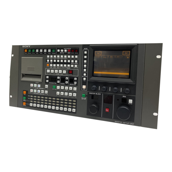
- Page 1 MASTER SETUP UNIT MSU-700A 電気製品は、安全のための注意事項を守らないと、火災 や人身事故になることがあります。 このオペレーションマニュアルには、 事故を防ぐための重要な注意事項と製 品の取り扱いかたを示してあります。 このオペレーションマニュアルをよく お読みのうえ、 製品を安全にお使いください。 お読みになったあとは、 いつ でも見られるところに必ず保管してください。 OPERATION MANUAL [Japanese/English] 1st Edition (Revised 1)
- Page 2 日本語 安全のために 電気製品は、 安全のための注意事項を守らないと、 火災や感電などにより死 警告表示の意味 亡や大けがなど人身事故につながることがあり、危険です。 オペレーションマニュアルおよ 事故を防ぐために次のことを必ずお守りください。 び製品では、次のような表示を しています。表示の内容をよく 安全のための注意事項を守る 理解してから本文をお読みくだ 2 ( J )〜3 ( J )ページの注意事項をよくお読みください。 さい。 定期点検を実施する 長期間安全に使用していただくために、 定期点検を実施することをおすすめ この表示の注意事項を守らない します。 点検の内容や費用については、 ソニーのサービス担当者または営業 と、火災や感電などにより死亡 担当者にご相談ください。 や大けがなど人身事故につなが ることがあります。 故障したら使用を中止する ソニーのサービス担当者、または営業担当者にご連絡ください。 この表示の注意事項を守らない 万一、異常が起きたら と、感電やその他の事故により けがをしたり周辺の物品に損害 1 電源を切る。 を与えたりすることがあります。 異常な音、 におい、 2 電源コードや接続コードを抜く。 煙が出たら 3 ソニーのサービス担当者、...
-
Page 3: Table Of Contents
メニューの構成と基本操作 ..................基本操作手順 ........................ 14(J) メニュー画面の基本構成 .................... 15(J) メニュー項目 ........................ 16(J) 22(J) 初期設定 ........................ 暗証番号の設定 ......................22(J) セキュリティステータスの設定 ................24(J) MSU-700Aの動作環境の設定 ..................26(J) 仕様 ........................31(J) BVP-700/900 シリーズカメラシステムのマニュアル構成 メ ンテナンスマニュアルとシステムマニュアルには、 システムの BVP-700/900シリ ーズのカメ ラシステムでは、オペレーシ ョ ンマ 構築のしかた、 設置、 接続、 システムと して使用するために必要... - Page 4 下記の注意を守らないと、 火災 感電 死亡 大けが や により や につながることがあります。 外装を外さない、改造しない 外装を外したり、改造したりすると、感電の原因となります。 内部の調整や設定および点検を行う必要がある場合は、 必ずサービストレー ニングを受けた技術者にご依頼ください。 内部に水や異物を入れない 水や異物が入ると火災や感電の原因となります。 万一、 水や異物が入ったときは、 すぐに電源を切り、 電源コードや接続コー ドを抜いて、 ソニーのサービス担当者または営業担当者にご相談ください。 指定の電源コードを使用する 指定以外の電源コードを使用すると、火災や感電の原因となります。 他の電源コードを使用する場合は、 ソニーのサービス担当者または営業担当 者にご相談ください。 電源コードを傷つけない 電源コードを傷つけると、火災や感電の原因となります。 ・ 電源コードを加工したり、傷つけたりしない。 ・ 重いものをのせたり、引っ張ったりしない。 ・ 熱器具に近づけたり、加熱したりしない。 ・ 電源コードを抜くときは、必ずプラグを持って抜く。 ・ ラックマウントするとき、レールにはさみ込まない。 万一、 電源コードが傷んだら、 ソニーのサービス担当者に交換をご依頼くだ さい。...
- Page 5 下記の注意を守らないと、 けが 損害 をしたり周辺の物品に を与えることがあります。 カードスロットに異物を入れない 指定の IC カード以外のものを入れると、火災や感電の原因となることがあ ります。 安全アースを接続する 安全アースを接続しないと、 感電の原因となることがあります。 次の方法で アースを接続してください。 • 電源コンセントが 極の場合 指定の電源コードを使用することで安全アースが接続されます。 • 電源コンセントが 極の場合 指定の3極→2極の変換プラグを 変換プラグ 使用し、変換プラグから出てい る緑色のアース線を建物に備え られているアース端子に接続し てください。 アース線 安全アースを取り付けることができない場合は、 ソニーのサービス担当者ま たは営業担当者にご相談ください。 3 (J)
-
Page 6: 主な特長
概要 マス ターセッ ト アップユニッ トMSU-700Aは、 ソニーのBVPシ リ ーズ リモートコントロールパネルとの同時コントロールが可能 のス タジオ/中継用CCDカラービデオカメ ラの調整機能を、 カメ ラ 本機と リモー ト コン ト ロールパネル RCP-700シリ ーズとの同時コン ト コ ン ト ロールユニッ ト(CCU)を介して リモー ト コン ト ロールするための ロールが可能です。 コン ト ロールパネルです。 HDTV システムの制御も可能... -
Page 7: 操作パネル
各部の名称と働き 操作パネル CLOSE ボタン STANDARD ボタン テスト信号出力選択ボタン AUTO SETUP 部 VF PW ボタン カメラ /CCU 機能 ON/OFF ボタン CAM PW ボタン シーンファイル操作部 ボタン メニュー操作部 AUTO SETUP MODE SKIN DTL LEVEL START/ CAM PW VF PW TEST1 TEST2 BARS CLOSE STANDARD BREAK WHITE BLACK AUTO HUE... - Page 8 各部の名称と働き 4 テスト信号出力選択ボタン AUTO SETUP ( オートセットアップ 部 押して点灯させる と、 カメ ラのテス ト信号発生器が作動し、 対応す カメ ラの自動調整を行います。 る信号が出力されます。 TEST 1 ( テスト ビデオ回路チェ ック用のガンマ波形のテス 2 3 4 ト信号 AUTO SETUP TEST 2 ( テスト : ビデオ回路チェ ック用の階段波形のテス ト SKIN DTL LEVEL START/ 信号...
- Page 9 /CCU ON/OFF SATURATION ( 8カメラ 機能 ボタン サチュレーション サチュレーシ ョ ン機能 CONTRAST ( ビデオカメ ラやCCUの機能を、 本機からON/OFFする こ とができ コントラスト コン ト ラス ト機能 BLACK GAMMA ( ブラックガンマ ます。 ブラ ッ クガンマ機能 CHARACTER ( 工場出荷時は、 18 個のボタ ンにそれぞれ次のスイ ッチ機能が割り 文字情報 システム情報表示機能。 当てられ、...
- Page 10 各部の名称と働き q; メニュー操作部 MODE MULTI CARD CONFIG MAINTENANCE FILE PAINT MODE ( 2 調整つまみ ロータリーエンコーダー モード選択 ボタン タ ッチパネルで選択した項目を調整します。 メニューのモー ドを選択します。 押して点灯させたボタ ンに対応するモー ドのメニューがELディ スプ ディスプレイ タッチパネル レイ に表示されます。 MODEボタ ンで選択したモー ドのメニューが表示され、各種の設 も う1 度押してボタ ンを消灯させる と、 メニュー表示も消灯します。 MULTI ( マルチ...
- Page 11 ACCESS ( カード挿入部 アクセス インジケーター ICメモリ ーカー ドの状態を表示します。 表示 意味 対応 消灯 カー ドが挿入されていません。 緑色に点灯 カー ドが挿入されています (電池状態は良 好)。 橙色に点灯 挿入したカー ドの電池が消耗し始めていま す。データは保持されていますが、早めに カー ドの電池を交換してく ださい。 橙色に点滅 挿入したカー ドの電池がほとんど消耗して ACCESS います。 MSUに挿入している間は MSU か ら通電されるので使用できますが、カー ド を抜く とデータは保持されません。電池を 交換してから使用してく ださい。 カードスロット 赤色に点灯...
- Page 12 各部の名称と働き qf カメラ選択部 PARA MULTI TALLY PANEL ACTIVE EXPAND 5 アクティブインジケーター PANEL ACTIVE ( パネルアクティブ ボタン それぞれ左から1〜12のカメ ラのコン ト ロール状態に応じて点灯し ボタ ンが消灯している と きに押すと点灯し、 カメ ラ選択ボタ ンで選 ます。 EXPANDボタ ン点灯時は、 13〜 24 のカメ ラメ ラのコ ン ト ロー 択したカメ ラを、本機からコ ン ト ロールでき る状態になり ます。 この ル状態に応じて点灯します。...
- Page 13 ECS/ シャッター制御部 左 、ガンマ制御部 中央 、マ qg フィルターコントロール部 スターゲイン制御部 右 FILTER CTRL ECS/SHUTTER GAMMA MASTER GAIN FILTER CTRL ( フィルターコントロール ボタン ECS ( エクステンデッドクリアスキャン) ボタン 押して点灯させる と、本機の NDボタンまたは CCボタ ンでフィ ル 押して点灯させる とビデオカメ ラがECSモー ドになり ます。 も う1度 ターを選択できる状態になり ます。 押して消灯させる...
- Page 14 各部の名称と働き MASTER GAIN ( マスターゲイン調整 ボタンと表示部 wa アイリス調整部 カメ ラの利得 (ゲイ ン) を調整します。 設定値 (単位dB) が表示部 に表示されます。 IRIS 利得は、 v(アップ)ボタ ンを押すたびに大き く なり、 V (ダウン) ボタ ンを押すたびに小さ く なり ます。 ボタ ンを押し続ける AUTO と連続して変わり ます。 IRIS/MB ACTIVE ( アイリス マスターブラックアク ティブ ボタン 押して点灯させる と、本機でレンズの絞り とマスターブラ ックを調 整できます。...
-
Page 15: コネクターパネル
MODE ( q; メニュー操作部 モード選択 ボタン 機器使用時の操作パネル メニュー操作部 (8ページ参照) のMODEボタ ンの1番上のボタ ン は、 HD/SD関係なく すべてのカメ ラシステムでFUNCTIONボタ ン /CCU ON/OFF 8カメラ 機能 ボタン と して機能します。 下図のよ う にラベルを貼って使用してく ださい。 本機をHDカメ ラシステム (HDC-700/750/700A/750A/900/950、 HDW-700/F900、 HDCU-700/900) で使用する ときは、 さ らに3つ MODE のカメ ラ/CCU機能ON/OFFボタ ン (7ページ参照) が有効になり FUNCTION ( ファンクション... -
Page 16: 基本操作手順
メニューの構成と基本操作 MSU-700A では、メニュー操作によ り、システム機器の調整など 項目を設定・調整する。 様々な機能に対応します。 • 設定・調整項目 (パラメーター) に対応するつまみを回して (またはボタ ンを押して) 、 希望の値に調整 (希望の設定を選 基本操作手順 択) します。 ◆次ページ 「設定・調整画面」 参照。 • メ ッセージが表示された場合は、 メ ッセージに従って操作し、 [OK]を押します。 MODE 設定・調整が終わったら Clear Home • 引き続き同じメニューの別の項目を調整する と き は、 その項目のボ MULTI タ ンを押します。... -
Page 17: メニュー画面の基本構成
メニュー画面の基本構成 初期画面(ペイントメニュー) 押すと、メニューの ページ目 設定値をクリアすることができます。 Clear Home に戻ります。 調整画面参照 V Mod Skin Sat / Detail Detail Contrast いずれかを押して、メニュー この画面で調整可能な項目 項目群 Gamma のページを切り換えます。 Black White Flare の名称が表示されます。調整したい /Knee 項目 項目群 の部分を押すと、押し ページ番号 総ページ数 た部分が反転表示となり、パネルの (1/3 は、ぺイントメニューが全部 下半分が調整画面になります。 で ページあり、現在 ページ目が 表示されていることを意味します 設定・調整画面(ペイントメニュー)... -
Page 18: メニュー項目
メニューの構成と基本操作 メニュー項目 操作/調整項目欄で●が付いている項目は調整つまみに割り当てられる項 目、それ以外の項目は、 メニュー画面上で操作する項目です。 マルチ制御メニュー MULTI ( ボタンで選択) メニュー 操作 調整項目 機能 Master/Slave Master マスター機の指定 Slave ス レーブ機の指定 All Slave すべてのカメ ラをス レーブ機に指定 All Off すべてのカメ ラのス レーブ指定を解除 Character Character on CNUキャ ラク ター出力 ON/OFF Default デフォル ト表示選択 System <#-#> コン ト ロールシステムの設定状態表示 Auto <#-#>... - Page 19 メンテナンスメニュー MAINTENANCE ( ボタンで選択) 次メニュー 次メニュー サブメニュー 操作 調整項目 機能 Adjusting Black Shading R/G/B H Saw/H Para/V Saw/V Para ブラ ッ クシェーディ ング調整 ● Auto B. Shading オー ト ブラ ッ クシェーディ ング調整 White Shading R/G/B H Saw/H Para/V Saw/V Para ホワイ ト シェーディ ング調整 ● White ホワイ トバラ ンス調整画面の選択 Auto W. Shading オー ト ホワイ ト シェーディ ング調整 Black Set Black Set R/G/B...
- Page 20 メニューの構成と基本操作 ファイル操作メニュー FILE ( ボタンで選択) メニュー サブメニュー 操作 調整項目 機能 Reference Ref Store リ フ ァ レンスフ ァイ ル登録 Ref Transfer CAM ->CARD リ フ ァ レンスフ ァイ ル転送 (カメ ラからICカー ド) CARD ->CAM リ フ ァ レンスフ ァイ ル転送 (ICカー ドからカメ ラ) CARD ->CAMs リ フ ァ レンスフ ァイ ル転送 ((ICカー ドから複数のカメ ラ) CAM ->CAMs リ...
- Page 21 ペイントメニュー PAINT ( ボタンで選択) ペイ ン ト メニューには1〜3があ り、 メニュー画面上で切り換えます。 ペイントメニュー メニュー サブメニュー 操作 調整項目 機能 Black R/G/B/Master ブラ ッ クバラ ンス調整 ● オー ト ブラ ッ クバラ ンス調整 White R/G/B ホワイ トバラ ンス調整 ● オー ト ホワイ トバラ ンス調整 Flare R/G/B フ...
- Page 22 メニューの構成と基本操作 ペイントメニュー (続き) メニュー サブメニュー 操作 調整項目 機能 Skin Detail 1/2/3 (項目共通) Level スキンディ テールレベル調整 ● Phase スキンディ テール色相調整 ● Width スキンディ テール色相幅調整 ● Saturation スキンディ テールサチュ レーシ ョ ン調整 ● Auto Hue # スキンディ テールオー ト ヒュー調整 (チャ ンネル別) Gate # スキンディ テールゲー トON/OFF (チャ ンネル別) Skin Dtl # スキンディ...
- Page 23 ペイントメニュー メニュー サブメニュー 操作 調整項目 機能 Matrix Matrix 1 R–G/G–B/B–R マ ト リ ッ クス定数設定 ● Matrix 2 R–B/G–R/B–G マ ト リ ッ クス定数設定 ● Multi Phase マルチマ ト リ ックス領域選択 ● マルチマ ト リ ックス色相設定 ● Saturation マルチマ ト リ ックス彩度設定 ●...
-
Page 24: 暗証番号の設定
初期設定 MSU-700Aを使用するシステムでは、 MSU-700Aからのコン ト ロ− MSU Configuration Exit ルの条件、および MSU-700A の動作環境を設定してく ださい。 MSU-700Aには、 接続したシステムに応じてMSU-700Aからコン ト ロールするカメ ラをアサイ ン したり 、 MSU-700A の操作機能を制限 MSU SW Adjusting するためのエンジニアモー ドがあ り ます。 Date / Security Time エンジニアモー ドの使用を特定のオペレーターに限定する ときは、 あ らかじめ暗証番号を設定します。 設定後は、 暗証番号を入力す... - Page 25 セキュ リ ティ メニュー項目が表示されます。 テンキーを使用して任意の暗証番号(1〜8桁)を入力し、 [OK] を押す。 Security Menu Exit ご注意 Engineer Mode 入力した暗証番号は、画面上ではすべて*で表示されます。 Code Status Change メ ッセージ 「Retype New Code No: (新しい暗証番号を再度 Engineer Mode 入力してく ださい) 」 が表示されます。 確認のため、 手順5で入力した暗証番号を再度入力し、 [OK] [Code Change]を押す。 を押す。 旧暗証番号(Old Code No.)入力欄が表示されます。 セキュ リ ティ メニュー画面に戻り ます。 Code Change [Exit]を押す。...
-
Page 26: セキュリティステータスの設定
初期設定 暗証番号を解除するには セキュリティステータスの設定 暗証番号を忘れてしまったり 、 担当者不在時に緊急にエンジニア 必要に応じて、 MSU-700Aのコン ト ロ−ル機能を制限する こ とがで モー ドでの設定が必要になった場合は、 次のよ う に暗証番号を解 きます。 除する こ と もできます。 この設定はエンジニアモー ドで行います。 PARAボタ ン、 PANEL ACTIVEボタ ンおよびカメ ラ選択ボタ ン 操作 1を押したまま、 MSU-700A の電源を入れる。 メニュー操作部 コンフィギュレーションメニュー PARA ボタン MODE WAVEFORM MONITOR... - Page 27 Enable Engineer Mode Engineer Mode View Paint Full Lock Mode Only ステータスを設定する。 [Engineer Mode]を押して反転させる。 [Ref. Enable] : MSU-700Aでのリ フ ァ レンスフ ァイ ルの設定を許 テンキーと、暗証番号(Code No.)入力欄が表示されます。 可する (工場出荷時: ON)。 Engineer Mode [Lens Enable] : MSU-700Aでのレンズフ ァイ ルの設定を許可す Code No: る (工場出荷時: ON)。 [OHB Enable] : MSU-700AでのOHBフ ァイ ルの設定を許可す る (工場出荷時: ON)。 [Full Lock] : MSU-700A のすべての操作を禁止する (工場出...
-
Page 28: Msu-700Aの動作環境の設定
初期設定 MSU-700A 時計を合わせるには の動作環境の設定 MSU-700Aには、 ICメモリ ーカー ドにリ ファ レンスフ ァイルやシーン MSUコンフ ィ ギュレーシ ョ ンメニューでは、 MSU-700Aに内蔵され フ ァイ ルを保存した日時を記録するための時計が内蔵されていま ている時計の時刻合わせや、警告ブザ−音の音量、 ラ ンプや EL す。 ディ スプレイ の明る さ を調整するこ と もできます。 時計合わせは、次の手順で行います。 コンフィギュレーションメニューを表示さ MSUコンフ ィ ギュレーシ ョ ンメニューの[Date/Time]を押す。 せるには... - Page 29 右端のつまみ(Master)で、マスター音量を調整できます。 [Exit]を押してメニューを抜けます。 ON/OFF ブザーを個別に するには 対応するボタ ンを押します。反転時が ONになり ます。 ブザーを設定するには [Call Buzzer]: コ−ル信号受信時のブザー [Touch Click]: メニュ−画面に表示された操作ボタ ンを押したと きの MSU-700A では、 コ−ル信号を受信したときや、パネルを操作す ブザー る とブザ−音が聞こえます。 [Switch Click]: 操作パネル上のボタ ンを押したときのブザー 必要に応じて、 ON/OFFしたり、音量を調整してく ださい。 設定は、次の手順で行います。 ブザ−音をすべて にするには [All Off]を押して反転させます。 MSUコンフ ィ ギュ レーシ ョ ンメニューの[MSU Adjusting]を押す。...
- Page 30 初期設定 ディスプレイの明るさを設定するには の明るさを設定するには メニュー操作部のディ スプレイ の明る さ を調整でき ます。 MSU-700A では、操作ボタ ンやタ リ ー表示部の LED の明る さ を調 調整は、次の手順で行います。 整できます。 調整は、次の手順で行います。 MSUコンフ ィ ギュ レーシ ョ ンメニューの[MSU Adjusting]を押し MSUコンフ ィ ギュ レーシ ョ ンメニューの[MSU Adjusting]を押し てMSU 設定メニューに切り換える。 て MSU 設定メニューに切り換える。...
- Page 31 スクリーンセーバーを設定するには スイッチ動作を選択するには 一定時間 MSU-700Aを操作しなかった場合、メニュー操作部の 調整画面での RGB の切り換えとPIX2 OUTPUTおよび WF2 ディ スプレイ 保護のためスク リ ーンセーバーが働きます。 OUTPUT端子の出力を連動させるかど うか (PIX/WF Synchro設 必要に応じて、 ON/OFFしたり、 動作するまでの時間を調整する こ 定) 、 オールモー ドのON/OFF (PIX/WF All Mode設定) 、 またモ とができます。 ニター選択ボタ ンの動作モー ド (PIX/WF Control Mode設定) を 設定は、次の手順で行います。 設定する こ とができ ます。...
- Page 32 初期設定 PIX/WF All Mode の設定 PIX/WF オールモー ドをON/OFF できます。 [ON]ボタ ンを押して ON/OFFを切り換えます。 ([ON]ボタ ン反転) : PICTURE MONITOR および WAVEFORM MONITOR の各ボタンは、選択されて いるグループのすべてのカメ ラに対して働きます。 OFF: PICTURE MONITORおよびWAVEFORM MONITORの 各ボタ ンはカメ ラ選択ボタ ンで選択したカメ ラに対してのみ働 きます。 PIX/WF Control Mode の設定 モニター選択ボタ ンの動作モー ドを選択できます。 希望のモー ドのボタ ンを反転させます。 [Direct]: ダイ レク トモー ド。 PICTURE MONITOR、...
- Page 33 仕様 一般 電源 AC 100 〜 240 V、 50/60 Hz 消費電流 0.45 A 動作温度 0℃〜 45℃ 最大ケーブル長 200 m 最大外形寸法 482 × 222 × 67 mm (幅 / 高さ/ 奥行き) 質量 約 4.5 kg 入出力端子 REMOTE CCU/CNU 8ピンマルチコネクター (1) 8ピンマルチコネクター (1) I/O PORT 50ピン (1) AC IN 3ピン (1) 付属品 オペレーシ ョ ンマニュアル (1) メ ンテナンスマニュアル Part 1 (1) HD 対応ラベル(1 式) 別売り品...
- Page 35 English For the customers in Europe WARNING This product with the CE marking complies with both the EMC Directive (89/336/EEC) and the Low Voltage Directive To prevent fire or shock hazard, do not expose the unit to (73/23/EEC) issued by the Commission of the European rain or moisture.
- Page 36 Initial Settings ................... 21(E) Specifying the Security Code ............21(E) Setting the Security Status ............. 23(E) Setting the Operating Conditions of the MSU-700A ....25(E) Specifications ..................30(E) Manuals for the BVP-700/900-series video camera system Three types of manuals are provided for the BVP-700/...
-
Page 37: Overview
These features ensure easy and error-free use of this unit. Touch panel for various operations In addition to the buttons and controls, the MSU-700A has a touch panel which permits various items to be selected and adjusted in menu format. -
Page 38: Locations And Functions Of Parts
Locations and Functions of Parts Operation Panel CLOSE button STANDARD button Signal output select buttons AUTO SETUP block VF PW button Camera/CCU function ON/OFF buttons CAM PW button Scene file control block ALL button Menu operation block AUTO SETUP MODE SKIN DTL LEVEL START/... - Page 39 4Signal output select buttons 7AUTO SETUP block Press and light up one of these buttons to activate the For automatic adjustments of cameras. test signal generator of the video camera and send the respective signals. 2 3 4 TEST 1: To send a gamma signal to test the video circuits AUTO SETUP TEST 2: To send a staircase signal...
- Page 40 Locations and Functions of Parts CHARACTER: System information display 8Camera/CCU function ON/OFF buttons function. When this button is lit (ON), the various Various functions of the video camera or the CCU can information on the entire system is displayed on be turned on and off from this unit.
- Page 41 q;Menu operation block MODE MULTI CARD CONFIG MAINTENANCE FILE PAINT 1 MODE (mode select) buttons 2 Control knobs (rotary encoders) Select the menu mode. Adjust the selected items on the touch panel. If you press and light one of these buttons, the menu for the selected mode appears on the EL display.
- Page 42 Flashes in orange The battery of the card in the slot is almost exhausted. While the card ACCESS stays in the MSU-700A, the MSU-700A supplies the power to the card. However when the card is ejected, the data cannot be maintained. Replace 1 IC card slot the battery before using.
- Page 43 qfCamera select block PARA MULTI TALLY PANEL ACTIVE EXPAND 1 PANEL ACTIVE button 5 Active indicators Press and light up this button to permit the cameras Show the control status of the corresponding cameras 1 selected with the camera select buttons to be controlled through 12 (when the EXPAND button is not lit) or 13 from this unit.
- Page 44 Locations and Functions of Parts qgFilter control block qhECS/Shutter control block (left) Gamma control block (center) Master gain control block (right) FILTER CTRL ECS/SHUTTER GAMMA MASTER GAIN 1 FILTER CTRL (filter control) button Press and light up the button to enable filter selection 1 ECS (Extended Clear Scan) button with the CC and ND filter select buttons of this unit.
- Page 45 5 MASTER GAIN select buttons and display wa Iris control block window Select the appropriate video gain according to the illumination of the subject to be shot. The selected IRIS value (dB) is displayed in the window. The gain value increases when the v (up) button is AUTO pressed and decreases when the V (down) button is pressed.
- Page 46 Locations and Functions of Parts Operation Panel in Use With HD Equipment q;Menu operation block/1 MODE (mode select) 8Camera/CCU function ON/OFF buttons buttons When this unit is used in an HD camera system (HDC- The uppermost MODE button in the menu operation 700/750/700A/750A/900/950, HDW-700/F900, block ( ) functions as the FUNCTION button...
-
Page 47: Basic Operating Procedure
Menu Configuration and Basic Menu Operations The MSU-700A provides menu operations for various Set or adjust the item (parameters). functions such as adjustments of system equipment. • Turn the control knobs (or press the button) to adjust (or set) the corresponding item Basic Operating Procedure (parameters) to the desired values. -
Page 48: Basic Configuration Of Menu Display
Menu Configuration and Basic Menu Operations Basic Configuration of Menu Display Initial display (Paint menu) To clear the adjusted values Clear Home Press to return to the first page (see the adjustment display). of the menu. V Mod Skin Sat / Detail Detail Contrast... -
Page 49: Menu Items
Menu Items The “Control items” marked with • are those assigned to the control knobs. The other items are operated on the menu display. Multi-Control menu (selected by pressing the MULTI button) Menu Control item Function Master/Slave Master Specifies the master unit. Slave Specifies the slave units. - Page 50 Menu Configuration and Basic Menu Operations Maintenance menu (selected by pressing the MAINTENANCE button) Menu 2ndary menu Submenu Control item Function Adjusting Black Shading R/G/B • H Saw/H Para/V Saw/V Para Adjusts the black shading. Auto B. Shading Executes the auto black shading. White Shading R/G/B •...
- Page 51 File control menu (selected by pressing the FILE button) Menu Submenu Control item Function Reference Ref. Store Stores the reference file. Ref. Transfer CAM ->CARD Transfers the reference file (from a camera to an IC card). CARD ->CAM Transfers the reference file (from an IC card to a camera). CARD ->CAMs Transfers the reference file (from an IC card to multiple cameras).
- Page 52 Menu Configuration and Basic Menu Operations Paint menus (selected by pressing the PAINT button) There are three Paint menus 1 through 3 to be selected on the menu display. Paint menu 1 Menu Submenu Control item Function Black • R/G/B/Master Adjusts the black balance.
- Page 53 Paint menu 1 (continued) Menu Control item Function SAT/Contrast • Saturation Adjusts the saturation. • Contrast Adjusts the contrast. Saturation Turns the saturation ON/OFF. Contrast Turns the contrast ON/OFF. Paint menu 2 Menu Control item Function Gamma Gamma 0.40/ 0.45/ 0.50 Sets the step gamma.
- Page 54 Menu Configuration and Basic Menu Operations Paint menu 3 Menu Submenu Control item Function Matrix Matrix 1 • R-G/G-B/B-R Adjusts the matrix coefficients. Matrix 2 • R-B/G-R/B-G Adjusts the matrix coefficients. Multi • (Patterns) Selects a range. • Phase Adjusts the multi matrix phase. •...
-
Page 55: Specifying The Security Code
Initial Settings For a system using the MSU-700A, you will need to MSU Configuration Exit set parameters for control of your system from the MSU-700A as well as the operating conditions of the MSU-700A. MSU SW Adjusting The MSU-700A has Engineer mode, which allows you... - Page 56 When you next press [Engineer Mode] on the Security Menu, the numeric keys appear, the code input is Press [Code Change]. requested, and the MSU-700A will enter Engineer mode if you enter the code properly and press [OK]. The numeric keys and field for entering the old code No.
-
Page 57: Setting The Security Status
To cancel the security code Setting the Security Status If the operator forgets the security code, or if an You can limit the control functions of the MSU-700A adjustment in Engineer mode becomes necessary in an when required. emergency when the unauthorized operator is absent, This status setting is enabled in Engineer mode. - Page 58 Mode Only Press [Engineer Mode] to set it to inverse video. Set the statuses for control from the MSU-700A. The numeric keys and field for entering the code [Ref. Enable]: Set it to inverse video to enable the No. are displayed.
-
Page 59: Setting The Operating Conditions Of The Msu-700A
To set the built-in clock Setting the Operating Conditions of the MSU-700A The MSU-700A has a built-in clock to record the date and time when reference and scene files are saved to By using the MSU Configuration menu, you can also IC memory cards. - Page 60 Press the corresponding button. When it is in inverse video, the buzzer is on. [Call Buzzer]: For the buzzer sound when a call signal A buzzer sounds on the MSU-700A when it receives is received call signal or a panel control is operated.
- Page 61 To adjust the brightness of the LEDs To adjust the brightness of the EL display You can adjust the brightness of the LEDs of the panel You can adjust the brightness of the display of the buttons and camera number/tally indication window. menu control block.
- Page 62 The screen saver can be activated to protect the menu You can specify whether to switch the outputs from display when the MSU-700A is not operated for a the PIX2 OUTPUT and WF2 OUTPUT connectors in synchronization with RGB switching on the certain time.
- Page 63 PIX/WF All Mode setting Turn on or off PIX/WF All mode. Press the [ON] button to turn on or off the mode. On ([ON] in inverse video): The PICTURE MONITOR and WAVEFORM MONITOR buttons have effect on all the connected cameras of the same group.
- Page 64 Specifications General Power requirements 100 to 240 V AC, 50/60 Hz Current consumption 0.45 A Peak inrush current (1) Power ON, current probe method: 20A(100V), 55A (240V) (2) Hot switching inrush current, measured in accordance with European standard EN55103-1: 12A (230V) Operating temperature 0°C to 45°C (32°F to 113°F) Maximum cable length 200 m (656 feet) 482 ×...
- Page 65 The material contained in this manual consists of information that is the property of Sony Corporation and is intended solely for use by the purchasers of the equipment described in this manual. Sony Corporation expressly prohibits the duplication of any...
- Page 66 Sony Corporation Communication System Solutions Network Company Printed in Belgium MSU-700A (SY) 2001.03.08 © 1999 3-866-896-02(1)