Table of Contents
Advertisement
OWNER'S MANUAL
Contents
PROFILE OF THIS UNIT ............................ 6
SPEAKER SETUP FOR THIS UNIT ........... 7
CONNECTIONS ......................................... 9
ADJUSTMENT BEFORE OPERATION .... 16
BASIC OPERATIONS .............................. 19
TUNING OPERATIONS ........................... 22
PROCESSOR (DSP) ................................ 26
SETTING THE SLEEP TIMER ................. 31
REMOTE CONTROL TRANSMITTER ..... 32
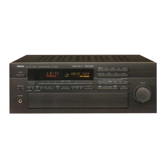
RX-V2090
Natural Sound Stereo Receiver
IMPORTANT!
Please record the serial number of this
unit in the space below.
Model:
Serial No.:
The serial number is located on the rear
of the unit.
Retain this Owner's Manual in a safe
place for future reference.
WARNING
TO REDUCE THE RISK OF FIRE OR
ELECTRIC SHOCK, DO NOT EXPOSE
THIS UNIT TO RAIN OR MOISTURE.
CAUTION
RISK OF ELECTRIC SHOCK
DO NOT OPEN
CAUTION: TO REDUCE THE RISK OF
ELECTRIC SHOCK, DO NOT REMOVE
COVER (OR BACK). NO USER-SERVICEABLE
PARTS INSIDE. REFER SERVICING TO
QUALIFIED SERVICE PERSONNEL.
Explanation of Graphical Symbols
The lightning flash with arrowhead
symbol, within an equilateral triangle,
is intended to alert you to the
presence of uninsulated "dangerous
voltage" within the product's
enclosure that may be of sufficient
magnitude to constitute a risk of
electric shock to persons.
The exclamation point within an
equilateral triangle is intended to
alert you to the presence of
important operating and
maintenance (servicing) instructions
in the literature accompanying the
appliance.
Advertisement
Table of Contents
Troubleshooting

Related Manuals for Yamaha RX-V2090


Summary of Contents for Yamaha RX-V2090
-
Page 1: Table Of Contents
TUNING OPERATIONS ... 22 USING THE DIGITAL SOUND FIELD PROCESSOR (DSP) ... 26 SETTING THE SLEEP TIMER ... 31 REMOTE CONTROL TRANSMITTER ... 32 RX-V2090 Natural Sound Stereo Receiver IMPORTANT! Please record the serial number of this unit in the space below. -
Page 2: Safety Instructions
SAFETY INSTRUCTIONS Read Instructions — All the safety and operating instructions should be read before the unit is operated. Retain Instructions — The safety and operating instructions should be retained for future reference. Heed Warnings — All warnings on the unit and in the operating instructions should be adhered to. - Page 3 UNIT! This product, when installed as indicated in the instructions contained in this manual, meets FCC requirements. Modifications not expressly approved by Yamaha may void your authority, granted by the FCC, to use the product. 2. IMPORTANT: When connecting this product to accessories and/or another product use only high quality shielded cables.
-
Page 4: Supplied Accessories
SUPPLIED ACCESSORIES After unpacking, check that the following parts are contained. Remote Control Transmitter Main Remote TRANSMIT USER /LEARN LEARN POWER SLEEP SKIP PHONO DISC SKIP SEARCH PAUSE/STOP PLAY DECK A/B PRESET A/B/C/D/E TUNER — SEARCH STOP PLAY TAPE 1 REC MUTE REC/PAUSE DIR A... - Page 5 Features • Seven Speaker Configuration Main: 100 W + 100 W (8 ) RMS Output Power, 0.015% THD, 20-20,000 Hz 120 W + 120 W (6 ) RMS Output Power, 0.04% THD, 20-20,000 Hz (USA Model Only) Center: 100 W (8 ) RMS Output Power, 0.015% THD, 1 kHz Front: 35 W + 35 W (8 ) RMS Output Power,...
-
Page 6: Profile Of This Unit
You are the proud owner of a Yamaha stereo receiver –an extremely sophisticated audio component. The Digital Sound Field Processor (DSP) built into this unit takes full advantage of Yamaha’s undisputed leadership in the field of digital audio processing to bring you a whole new world of listening experiences. Follow the instructions in this manual carefully when setting up your system, and this unit will sonically transform your room into a totally new listening environment –movie theater, concert hall, and so on. -
Page 7: Speaker Setup For This Unit
SPEAKER SETUP FOR THIS UNIT SPEAKERS TO BE USED This unit is designed to provide the best sound-field quality with a seven speaker configuration. The speakers to be used with this unit will be main speakers, front speakers, rear speakers, and a center speaker. The main speakers are used for the main source sound. -
Page 8: Speaker Placement
SPEAKER PLACEMENT The recommended speaker configuration, the seven-speaker configuration, will require three speaker pairs: main speakers, front speakers, and rear speakers, plus a center speaker. When you place these speakers, refer to the following: Front R Front L Main R Center Main L Rear L... -
Page 9: Connections
CAUTION Before attempting to make any connections to or from this unit, be sure to first switch OFF the power to this unit and to any other components to which connections are being made. CONNECTIONS WITH OTHER COMPONENTS When making connections between this unit and other components, be sure all connections are made correctly, that is to say L (left) to L, R (right) to R, “+”... -
Page 10: Connecting Speakers
CONNECTING SPEAKERS Connect the respective speakers to this unit as shown below: Right Note on main speaker connection: One or two speaker systems can be connected to this unit. If you connect only one speaker system, connect it to either the SPEAKERS A or B terminals. Note on center speaker connection: One or two center speakers can be connected to this unit. - Page 11 With some subwoofers, including the Yamaha Active Servo Processing Subwoofer System, the amplifier and subwoofer are in the same unit. CENTER OUTPUT terminal This terminal is for center channel line output.
- Page 12 TAPE 2 MAIN MAIN CH MAIN LEVEL MAIN CH — MAIN IN terminals These terminals are for line input to the built-in main channel amplifier. Leave the jumper bars connected to the PRE OUT terminals when you use the built-in amplifier. However, if you drive main speakers with an external stereo power amplifier, remove the jumper bars.
- Page 13 CONNECTING S VIDEO TERMINALS If your video cassette recorder, video disc player, monitor, etc., is equipped with “S” (high-resolution) video terminals, connect them to this unit’s S VIDEO terminals. Otherwise, use the composite video terminals of the unit. Note: • If video signals are sent to both the S VIDEO input and composite input terminals, the input signals will be sent to the respective S VIDEO output and composite output terminals independently.
- Page 14 • A video monitor for the second room. Note Since there are so many ways to connect and use your RX-V2090 in a multi-room installation, we recommend that you consult with a custom installation specialist for the Room 2 connections which will best meet your require- ments.
-
Page 15: Antenna Connections
ANTENNA CONNECTIONS • Each antenna should be connected to the designated terminals correctly, referring to the following diagram. • Both AM and FM indoor antennas are included with this unit. In general, these antennas will probably provide sufficient signal strength. Nevertheless, a properly installed outdoor antenna will give clearer reception than an indoor one. -
Page 16: Adjustment Before Operation
ADJUSTMENT BEFORE OPERATION SPEAKER BALANCE ADJUSTMENT This procedure lets you adjust the sound output level balance between the main, front, center, and rear speakers using the built-in test tone generator. With this adjustment, the sound output level heard at the listening position will be the same from each speaker. - Page 17 Select the center channel output mode according to your speaker configuration. (Refer to “SPEAKER CONFIGURATION” on page 7.) CENTER MODE NORMAL WIDE PHANTOM TEST Press the TEST button to run the Dolby test. Turn up the volume using the remote control transmitter. You will hear a test tone (like pink noise) from the left main speaker, then the center speaker, then the right main speaker, and then the rear speakers, for about two...
- Page 18 Adjust the BALANCE control so that the test tone sound output level of the left front speaker and the right front speaker are the same. BALANCE Adjust the test tone sound output level of the center speaker to be at the same level as that of the main speakers with the CENTER LEVEL keys.
-
Page 19: Basic Operations
To play a source Set to the “ ” position. VOLUME –dB Press the POWER switch to turn on the power. Select the desired input source by using the input selector buttons. (For video sources, turn the video monitor ON.) TAPE 2 MONITOR TAPE 1... - Page 20 To record a source to tape (or dub from tape to tape) Select the source to be recorded. REC OUT SOURCE LD/TV TAPE 1 VCR 1 VCR 2 VIDEO AUX Play the source and press the corresponding input selector, then turn the VOLUME control up to confirm the input source.
- Page 21 Selecting the SPEAKERS system Because one or two speaker systems (as main speak- ers) can be connected to this unit, the SPEAKERS switches allow you to select speaker system A or B, or both at once. SPEAKERS Adjusting the BALANCE control Adjust the balance of the output volume to the left and right speakers to compensate for sound imbal- ance caused by speaker location or listening room...
-
Page 22: Tuning Operations
Normally, if station signals are strong and there is no interference, quick automatic-search tuning (AUTOMATIC TUNING) is possible. However, if signals of the station you want to select are weak, you must tune to it manually (MANUAL TUNING). AUTOMATIC TUNING Select the reception band (FM or AM) while watching the display. - Page 23 PRESET TUNING Manual Preset Tuning This unit can store station frequencies (selected by tuning operation) by using the preset station buttons. With this function, you can select any desired station by only pressing the corresponding preset station button. Up to 40 stations (8 stations 5 pages) can be stored.
- Page 24 Automatic Preset Tuning You can also make use of an automatic preset tuning function for FM stations only. By this function, this unit performs automatic tuning and stores FM stations with strong signals sequentially. Up to 40 stations are stored automatically in the same way as in the manual preset tuning method on page 23.
- Page 25 Exchanging Preset Stations You can exchange the places of two preset stations with each other as shown below. (Example) If you want to shift the preset station on E1 to A5, and vice versa. Recall the preset station on E1 (by following the method of “To recall a preset station”...
-
Page 26: Using The Digital Sound Field Processor (Dsp)
USING THE DIGITAL SOUND FIELD PROCESSOR (DSP) This unit incorporates a sophisticated, multi-program digital sound field processor, which allows you to expand and shape the audio sound field from both the audio and video sources, for a theater-like experience in the listen- ing/viewing room. - Page 27 This program is effective for playback of sources encoded with Dolby Surround. The Yamaha DSP technology is ideally combined with the Dolby Pro Logic to present you the incredible listening experience of the 70 mm movie theater. This program is ideal for pre- cisely reproducing the sound design of the newest movies.
- Page 28 To play a source with the digital sound field processor Follow steps 1 - 6 shown in “BASIC OPERATIONS” on page 19. Select the desired program that is suitable for the source. DIGITAL SOUND FIELD PROCESSOR 70mm PRO LOGIC ENHANCED MOVIE THEATER ROCK CONCERT...
-
Page 29: Adjustment Of The Center Level
The following adjustments can be done on the remote control transmitter as well as on the front panel. Adjustment of the FRONT LEVEL You can “fine-tune” the sound output level of the front effects speakers after setting the output level according to the instructions in “Speaker balance adjustment”... -
Page 30: Adjustment Of Delay Time
Adjustment of DELAY TIME You can adjust the time difference between the beginning of the source sound and the beginning of the effect sound with the DELAY TIME control. The DELAY TIME control is effective with all programs. By applying more or less delay, sound effects, background noise, and ambient noise coming at you from the rear speakers can be enhanced or subdued for extra effect. -
Page 31: Setting The Sleep Timer
SETTING THE SLEEP TIMER If you use the SLEEP timer of this unit, you can make this unit turn off automatically. When you are going to sleep while enjoying a broadcast or other desired input source, this timer function is helpful. Notes: •... -
Page 32: Remote Control Transmitter
REMOTE CONTROL TRANSMITTER Battery installation Main Room Remote Room 2 Remote Battery replacement If you find that the remote control transmitter must be used closer to the main unit, the batteries are weak. Replace both batteries with new ones. Notes: •... - Page 33 The remote control transmitter provided with this unit is designed to control all the most commonly used functions of the unit. If the CD player, tape deck, etc. connected to this unit are YAMAHA components designed for remote control compatibilty, then this remote control transmitter will also control various functions of each component.
- Page 34 For Other Component Control Identify the remote control transmitter keys with your component’s keys. If these keys are identical, their functions will be the same. On each key function, refer to the corresponding instruction on your component’s manual. CD player keys Controls compact disc player.
- Page 35 YPC-USER-LEARN switc YPC : Set to this position when using preset POWER SLEEP SKIP PHONO DISC SKIP SEARCH PAUSE/STOP PLAY ・ “YPC” is the abbreviation of YAMAHA DECK A/B PRESET A/B/C/D/E TUNER — USER SEARCH STOP PLAY TAPE 1 REC MUTE...
- Page 36 To learn a new function Set to the “LEARN” position. USER Press a key on this unit where a new function will be learned. Press and hold the key (on the other remote control transmitter) where the desired new function is. Lights up •...
-
Page 37: Troubleshooting Guide
To clear a learned function Set to the “ ” position. USER USER LEARN Press and hold the CLEAR button using the point of a mechanical pencil, etc. CLEAR Press and hold the key where the learned function to be deleted is until the indicator flashes 3 times. -
Page 38: Troubleshooting
If the unit fails to operate normally, check the following points to determine whether the fault can be corrected by the simple measures suggested. If it cannot be corrected, or if the fault is not listed in the SYMPTOM column, disconnect the power cord and contact your authorized YAMAHA dealer or service center for help. SYMPTOM The unit fails to turn on when the POWER switch is pressed. -
Page 39: Specifications
SPECIFICATIONS AUDIO SECTION Minimum RMS Output Power per Channel MAIN L, R 8 ohms, 20 Hz to 20 kHz, 0.015% THD ... 100W+100W 6 ohms, 20 Hz to 20 kHz, 0.04% THD [U.S.A. model only] ... 120W+120W Center 8 ohms, 1 kHz, 0.015% THD ... 100W Front L, R 8 ohms, 1 kHz, 0.08% THD ... - Page 40 YAMAHA ELECTRONIQUE FRANCE S.A. RUE AMBROISE CROIZAT BP70 CROISSY-BEAUBOURG 77321 MARNE-LA VALLEE-CEDEX 2, FRANCE YAMAHA ELECTRONICS (UK) LTD. YAMAHA HOUSE, 200 RICKMANSWORTH ROAD WATFORD, HERTS WD1 7JS, ENGLAND YAMAHA SCANDINAVIA A.B J A WETTERGRENS GATA 1, BOX 30053, 400 43 VÄSTRA FRÖLUNDA, SWEDEN VT26690 Printed in Japan...