Table of Contents
Advertisement
Industrial controls
Safety technology
3TK28 safety relays
Manual
07/2016
NEB926157502000/RS-AB/003
___________________
Introduction
___________________
Product-specific safety
information
___________________
Description of the individual
safety relays
Mounting
Connection
Dimension drawings
___________________
Accessories
1
2
3
4
5
6
7
Advertisement
Table of Contents

Related Manuals for Siemens 3TK28


Summary of Contents for Siemens 3TK28
- Page 1 ___________________ Introduction ___________________ Product-specific safety information ___________________ Description of the individual Industrial controls safety relays Mounting Safety technology 3TK28 safety relays Connection Dimension drawings Manual ___________________ Accessories 07/2016 NEB926157502000/RS-AB/003...
- Page 2 Note the following: WARNING Siemens products may only be used for the applications described in the catalog and in the relevant technical documentation. If products and components from other manufacturers are used, these must be recommended or approved by Siemens. Proper transport, storage, installation, assembly, commissioning, operation and maintenance are required to ensure that the products operate safely and without any problems.
-
Page 3: Table Of Contents
Overview ........................... 14 General technical data ....................... 18 Cable lengths ........................19 General information about enabling and signaling circuits ..........20 3TK28 safety relays with relay enabling circuits ..............21 3.6.1 3TK2810-0 safety relay ..................... 21 3.6.1.1 Applications ........................21 3.6.1.2... - Page 4 State diagrams 3TK2827 / 3TK2828 ...................86 3.6.7.7 Technical data 3TK2827 / 3TK2828 ..................87 3.6.7.8 Connection examples 3TK2827 / 3TK2828 .................93 3.6.8 3TK2830 expansion unit .....................96 3.6.8.1 Applications........................96 3.6.8.2 Description of function and connection information .............96 3.6.8.3 Structure 3TK2830 ......................97 3TK28 safety relays Manual, 07/2016, NEB926157502000/RS-AB/003...
- Page 5 State diagrams 3TK2842 ....................130 3.7.3.7 Technical data 3TK2842 ....................131 3.7.3.8 Connection examples 3TK2842 ..................133 3TK28 safety relays with contactor relay enabling circuits ..........136 3.8.1 3TK2805 / 3TK2806 safety relays ..................136 3.8.1.1 Applications ........................136 3.8.1.2 Description of function and connection information ............
- Page 6 Disassembling the device ....................186 Connection ..........................189 Connection data for terminal blocks ..................189 Connecting terminal blocks ....................190 Disconnecting ........................192 Plugging in terminal blocks ....................194 Dimension drawings ........................195 Dimension drawings 3TK28 ....................195 Accessories..........................205 3TK28 safety relays Manual, 07/2016, NEB926157502000/RS-AB/003...
-
Page 7: Introduction
● Safety systems Validity range The manual is valid for the available 3TK28 safety relays. It describes the components that are valid at the time of publication. SIEMENS reserves the right of including a Product Information for each new component, and for each component of a later version. -
Page 8: Definitions
Nor can Siemens assume liability for recommendations that appear or are implied in the following description. No new guarantee, warranty, or liability claims beyond the scope of the Siemens general terms of supply are to be derived or inferred from the following description. 3TK28 safety relays... -
Page 9: Product-Specific Safety Information
Proper use of hardware products This equipment is only allowed to be used for the applications described in the catalog and in the technical description, and only in conjunction with non-Siemens equipment and components recommended by Siemens. Correct transport, storage, installation and assembly, as well as careful operation and maintenance, are required to ensure that the product operates safely and without faults. -
Page 10: Current Information About Operational Safety
EC Directives* stated (including amendments) and that the stated standards* were applied in their design and construction. * You can download the complete EC Declaration of Conformity as a PDF. 3TK28 safety relays Manual, 07/2016, NEB926157502000/RS-AB/003... -
Page 11: General Safety Notes
Safety category 4 per DIN EN 954-1 / SIL 3 per IEC 61508 / PL e per DIN EN ISO 13849-1 The 3TK28 safety relays have been designed such that applications up to category 4 per DIN EN 954-1 / SIL 3 per IEC 61508 / PL e per DIN EN ISO 13849-1 can be implemented. -
Page 12: Safety Information For Hazardous Areas
Hazardous Voltage. Can Cause Death, Serious Injury, or Property Damage. Installation of the 3TK28 safety relays in hazardous areas The components of the 3TK28 are not suitable for installation in hazardous areas. Please contact your ATEX specialist. 3TK28 safety relays... -
Page 13: Description Of The Individual Safety Relays
Description of the individual safety relays Introduction SIRIUS 3TK28 safety relays are mainly used in autonomous safety applications that are not connected to a safety-related bus system. Here they are used to evaluate sensors and ensure safety-related shutdown in case of a hazard. They also check and monitor the sensors, actuators, and the safety-related functions of the safety relay. -
Page 14: Overview
Description of the individual safety relays 3.2 Overview Overview Overview of 3TK28 safety relays The following tables provide an overview of the 3TK28 safety relays. 3TK28 safety relays with relay enabling circuits 3TK28.. SENSORS Electromechanical Solid-state Magnetically-operated switches START TYPE... - Page 15 Delayed SIGNALING CIRCUITS Relay Solid-state Max. achievable SIL acc. to IEC 61508 / IEC 62061 Max. achievable PL acc. to EN ISO 13849-1 3TK28 safety relays with contactor relay enabling circuits 3TK28.. SENSORS Electromechanical Solid-state Magnetically-operated switches START TYPE Auto...
- Page 16 Description of the individual safety relays 3.2 Overview 3TK28 speed/standstill monitoring 3TK28.. 10-0 10-1 SENSORS Electromechanical Solid-state Magnetically-operated switches START TYPE Auto Monitored ENABLING CIRCUITS Instantaneous 3 NO + 1 NC 2 NO Delayed SIGNALING CIRCUITS Relay 1 CO Solid-state Achievable SIL / PL Max.
- Page 17 Description of the individual safety relays 3.2 Overview 3TK28 multifunctional devices 3TK28.. SENSORS Electromechanical Solid-state Magnetically-operated switches START TYPE Auto Monitored ENABLING CIRCUITS Instantaneous See manual See manual 3TK2826 3TK2845 Delayed SIGNALING CIRCUITS Relay See manual See manual 3TK2826 3TK2845 Solid-state Max.
-
Page 18: General Technical Data
Description of the individual safety relays 3.3 General technical data General technical data Technical data valid for all 3TK28 products in this manual. Product brand name SIRIUS Product designation Safety relay Version of the product for EMERGENCY STOP and protective doors... -
Page 19: Cable Lengths
3.4 Cable lengths Cable lengths The cable lengths specified in the table are valid for a cable cross-section of 1.5 mm². Sensor - evaluation unit distance for 3TK28 devices Sensor - evaluation unit distance Sensor - evaluation unit distance in meters (1-channel) -
Page 20: General Information About Enabling And Signaling Circuits
3.5 General information about enabling and signaling circuits General information about enabling and signaling circuits Relay enabling circuits: When a safety function is requested or a fault detected, the 3TK28 safety relays enter the safe state. This means: Relay enabling circuits with NO function OPEN... -
Page 21: 3Tk28 Safety Relays With Relay Enabling Circuits
Description of the individual safety relays 3.6 3TK28 safety relays with relay enabling circuits 3TK28 safety relays with relay enabling circuits 3.6.1 3TK2810-0 safety relay 3.6.1.1 Applications Applications of the 3TK2810-0 safety relay You can use the 3TK2810-0 safety relays for safety standstill detection on 3-phase and 1-phase induction motors, e.g. - Page 22 Description of the individual safety relays 3.6 3TK28 safety relays with relay enabling circuits Device properties ● PL per EN ISO 13849-1; SIL 3 per IEC 61508 / IEC 62061 ● Wire-break detection in the measurement circuit ● Positive-action safe output contacts: 3 NO contacts, 1 NC contact for 250 V AC ●...
-
Page 23: Structure Of The 3Tk2810-0
Description of the individual safety relays 3.6 3TK28 safety relays with relay enabling circuits 3.6.1.3 Structure of the 3TK2810-0 Front view Meaning ① Display LEDs ② Removable terminal blocks ③ Time setting ④ Labels 3.6.1.4 Terminal assignment Terminal Description L/+ control supply voltage U... -
Page 24: Display Of The Operating State
Description of the individual safety relays 3.6 3TK28 safety relays with relay enabling circuits 3.6.1.5 Display of the operating state The operating state and functioning of the device are indicated by three LEDs: ● DEVICE – lights up green during operation –... -
Page 25: State Diagram 3Tk2810-0
Description of the individual safety relays 3.6 3TK28 safety relays with relay enabling circuits 3.6.1.6 State diagram 3TK2810-0 Figure 3-1 : Detection time after wire break 3TK28 safety relays Manual, 07/2016, NEB926157502000/RS-AB/003... -
Page 26: Technical Data 3Tk2810-0
Description of the individual safety relays 3.6 3TK28 safety relays with relay enabling circuits 3.6.1.7 Technical data 3TK2810-0 3TK2810-0G... 3TK2810-0B... EMC emitted interference IEC 61000-6-2, IEC 61000-6-3 Item designation according to DIN 40719 extendable after • IEC 204-2 according to IEC 750 according to DIN EN 61346-2 •... - Page 27 Description of the individual safety relays 3.6 3TK28 safety relays with relay enabling circuits 3TK2810-0G... 3TK2810-0B... Number of outputs as contact-affected switching element as NO contact safety-related as contact-affected switching element as NC • contact for reporting function instantaneous switching as contact-affected switching element as NO •...
- Page 28 Description of the individual safety relays 3.6 3TK28 safety relays with relay enabling circuits 3TK2810-0G... 3TK2810-0B... Design of the fuse link for short-circuit quick: 5 A protection of the NO contacts of the relay outputs required Type of voltage of the controlled supply...
- Page 29 Description of the individual safety relays 3.6 3TK28 safety relays with relay enabling circuits 3TK2810-0G... 3TK2810-0B... Product function automatic start • rotation speed monitoring • laser scanner monitoring • light grid monitoring • light barrier monitoring • magnetic switch monitoring Normally closed •...
- Page 30 Description of the individual safety relays 3.6 3TK28 safety relays with relay enabling circuits Input data (L1-L2-L3) Measurement/motor voltage Max. 690 AC (IEC), max. 600 AC (UL) Input resistances kΩ Approx. 400 Reponse value Uan Approx. 20 ... 400; settable Standstill time ts 0.2 ...
-
Page 31: Connection Examples 3Tk2810-0
Description of the individual safety relays 3.6 3TK28 safety relays with relay enabling circuits 3.6.1.8 Connection examples 3TK2810-0 * Motor contactors Figure 3-3 Without evaluation of the feedback circuit * Motor contactors Figure 3-4 With evaluation of the feedback circuit... - Page 32 Description of the individual safety relays 3.6 3TK28 safety relays with relay enabling circuits ① With jumper between X2-X3 for automatic acknowledgment of open-circuit detection Figure 3-5 Use of the 3TK2810-0 standstill monitor in a wye-delta connection 3TK28 safety relays...
-
Page 33: 3Tk2820 Safety Relay
Description of the individual safety relays 3.6 3TK28 safety relays with relay enabling circuits 3.6.2 3TK2820 safety relay 3.6.2.1 Applications Applications of the 3TK2820 safety relay You can use the 3TK2820 safety relay in EMERGENCY STOP devices according to DIN EN ISO 13850 and in safety circuits according to VDE 0113-1 or DIN EN 60204-1, e.g. -
Page 34: Structure 3Tk2820
Description of the individual safety relays 3.6 3TK28 safety relays with relay enabling circuits 3.6.2.3 Structure 3TK2820 Front view Meaning ① Display LEDs ② Removable terminal blocks ③ Selector switch ④ Labels 3.6.2.4 Terminal assignment Terminal Description Sensor channel 1... -
Page 35: Display Of The Operating State
Description of the individual safety relays 3.6 3TK28 safety relays with relay enabling circuits 3.6.2.5 Display of the operating state Two LEDs and a slide switch indicate the operating state and functioning of the device: ● DEVICE ● OUT Operating state of 3TK2820... -
Page 36: Installation 3Tk2820
Description of the individual safety relays 3.6 3TK28 safety relays with relay enabling circuits 3.6.2.6 Installation 3TK2820 Warning notices Warning notices before installation, wiring, and commissioning WARNING Hazardous voltage! Can cause electric shock and burns. Turn off and lock out all power supplying this device before working on this device. - Page 37 Description of the individual safety relays 3.6 3TK28 safety relays with relay enabling circuits Disassembling the device WARNING Hazardous Voltage. Can Cause Death, Serious Injury, or Property Damage. Before starting work, therefore, disconnect the system and devices from the power supply.
-
Page 38: Connection 3Tk2820
Description of the individual safety relays 3.6 3TK28 safety relays with relay enabling circuits 3.6.2.7 Connection 3TK2820 Connection data for terminal blocks Specification and value Specification and value in the case of removable in the case of removable terminal blocks with spring-... - Page 39 Description of the individual safety relays 3.6 3TK28 safety relays with relay enabling circuits Connecting terminal blocks WARNING Hazardous Voltage. Can Cause Death, Serious Injury, or Property Damage. Before starting work, therefore, disconnect the system and devices from the power supply.
- Page 40 Description of the individual safety relays 3.6 3TK28 safety relays with relay enabling circuits Disconnecting WARNING Hazardous Voltage. Can Cause Death, Serious Injury, or Property Damage. Before starting work, therefore, disconnect the system and devices from the power supply. Removing terminal blocks from the device...
- Page 41 Description of the individual safety relays 3.6 3TK28 safety relays with relay enabling circuits Plugging in terminal blocks WARNING Hazardous Voltage. Can Cause Death, Serious Injury, or Property Damage. Before starting work, therefore, disconnect the system and devices from the power supply.
-
Page 42: Technical Data 3Tk2820
Description of the individual safety relays 3.6 3TK28 safety relays with relay enabling circuits 3.6.2.8 Technical data 3TK2820 3TK2820-.AJ.. 3TK2820-.AL.. 3TK2820-.CB.. EMC emitted interference IEC 60947-5-1, IEC 61000 Item designation — according to DIN 40719 extendable after • IEC 204-2 according to IEC 750 according to DIN EN 61346-2 •... - Page 43 Description of the individual safety relays 3.6 3TK28 safety relays with relay enabling circuits 3TK2820-.AJ.. 3TK2820-.AL.. 3TK2820-.CB.. Stop category according to DIN EN 60204-1 Design of the input — cascading-input/functional switching • feedback input • start input • Design of the electrical connection jumper...
- Page 44 Description of the individual safety relays 3.6 3TK28 safety relays with relay enabling circuits 3TK2820-.AJ.. 3TK2820-.AL.. 3TK2820-.CB.. Product function automatic start • rotation speed monitoring • laser scanner monitoring • light grid monitoring • light barrier monitoring • magnetic switch monitoring Normally closed •...
-
Page 45: Connection Examples 3Tk2820
Description of the individual safety relays 3.6 3TK28 safety relays with relay enabling circuits 3.6.2.9 Connection examples 3TK2820 Figure 3-6 Autostart (2-channel) Figure 3-7 Monitored start (2-channel) 3TK28 safety relays Manual, 07/2016, NEB926157502000/RS-AB/003... - Page 46 Description of the individual safety relays 3.6 3TK28 safety relays with relay enabling circuits Figure 3-8 Autostart (1-channel) Figure 3-9 Monitored start (1-channel) 3TK28 safety relays Manual, 07/2016, NEB926157502000/RS-AB/003...
-
Page 47: 3Tk2822 / 3Tk2823 Safety Relays
Description of the individual safety relays 3.6 3TK28 safety relays with relay enabling circuits 3.6.3 3TK2822 / 3TK2823 safety relays 3.6.3.1 Applications Applications of the 3TK2822/23 safety relay You can use the 3TK2822 safety relay in safety circuits according to DIN EN / IEC 60204-1, e.g. -
Page 48: Structure 3Tk2822/23
Description of the individual safety relays 3.6 3TK28 safety relays with relay enabling circuits 3.6.3.4 Structure 3TK2822/23 Front view Meaning ① Display LEDs ② Removable terminal blocks ③ Labels 3.6.3.5 Terminal assignment Terminal Description Y11; Y12 Channel 1, EMERGENCY STOP or limit switch Y21;... -
Page 49: Display Of The Operating State
Description of the individual safety relays 3.6 3TK28 safety relays with relay enabling circuits 3.6.3.6 Display of the operating state The operating state and functioning of the device are indicated by three LEDs: ● POWER ● CHANNEL 1 ● CHANNEL 2... -
Page 50: State Diagrams 3Tk2822 / 3Tk2823
Description of the individual safety relays 3.6 3TK28 safety relays with relay enabling circuits 3.6.3.7 State diagrams 3TK2822 / 3TK2823 Figure 3-10 State diagram 3TK2822 Figure 3-11 State diagram 3TK2823 3TK28 safety relays Manual, 07/2016, NEB926157502000/RS-AB/003... -
Page 51: Technical Data 3Tk2822 / 3Tk2823
Description of the individual safety relays 3.6 3TK28 safety relays with relay enabling circuits 3.6.3.8 Technical data 3TK2822 / 3TK2823 3TK2822-..3TK2823-..EMC emitted interference EN 60947-5-1 Item designation according to DIN 40719 extendable after IEC 204-2 • according to IEC 750 according to DIN EN 61346-2 •... - Page 52 Description of the individual safety relays 3.6 3TK28 safety relays with relay enabling circuits 3TK2822-..3TK2823-..Design of the electrical connection jumper socket Switching capacity current — at AC-15 at 24 V • of the NO contacts of the relay outputs •...
- Page 53 Description of the individual safety relays 3.6 3TK28 safety relays with relay enabling circuits 3TK2822-..3TK2823-..Product function automatic start • rotation speed monitoring • laser scanner monitoring • light grid monitoring • light barrier monitoring • magnetic switch monitoring Normally closed contact- •...
-
Page 54: Connection Examples 3Tk2822 / 3Tk2823
Description of the individual safety relays 3.6 3TK28 safety relays with relay enabling circuits 3.6.3.9 Connection examples 3TK2822 / 3TK2823 Figure 3-12 Autostart (2-channel) Figure 3-13 Monitored start (2-channel) 3TK28 safety relays Manual, 07/2016, NEB926157502000/RS-AB/003... -
Page 55: 3Tk2821 / 3Tk2824 Safety Relays
Description of the individual safety relays 3.6 3TK28 safety relays with relay enabling circuits 3.6.4 3TK2821 / 3TK2824 safety relays 3.6.4.1 Applications Applications of the 3TK2821/24 safety relay You can use the 3TK2821/24 safety relays in EMERGENCY STOP devices according to DIN EN / IEC 60947-5-5 and in safety circuits according to DIN EN / IEC 60204-1, as a basic unit or contact extension. -
Page 56: Structure 3Tk2821/24
Description of the individual safety relays 3.6 3TK28 safety relays with relay enabling circuits 3.6.4.3 Structure 3TK2821/24 Front view Meaning ① Display LEDs ② Removable terminal blocks ③ Labels 3.6.4.4 Terminal assignment Terminal Description Y1; Y1 On button, feedback circuit 13;... -
Page 57: Display Of The Operating State
Description of the individual safety relays 3.6 3TK28 safety relays with relay enabling circuits 3.6.4.5 Display of the operating state The operating state and functioning of the device are indicated by three LEDs: ● POWER ● CHANNEL 1 ● CHANNEL 2... -
Page 58: Technical Data 3Tk2821 / 3Tk2824
Description of the individual safety relays 3.6 3TK28 safety relays with relay enabling circuits 3.6.4.7 Technical data 3TK2821 / 3TK2824 3TK2821-.C... 3TK2824-.B... 3TK2824-.C... EMC emitted interference EN 60947-5-1 Item designation according to DIN 40719 extendable after • IEC 204-2 according to IEC 750 according to DIN EN 61346-2 •... - Page 59 Description of the individual safety relays 3.6 3TK28 safety relays with relay enabling circuits 3TK2821-.C... 3TK2824-.B... 3TK2824-.C... Design of the electrical connection jumper socket Switching capacity current — at AC-15 at 24 V • of the NO contacts of the relay outputs •...
- Page 60 Description of the individual safety relays 3.6 3TK28 safety relays with relay enabling circuits 3TK2821-.C... 3TK2824-.B... 3TK2824-.C... Product function automatic start • rotation speed monitoring • laser scanner monitoring • light grid monitoring • light barrier monitoring • magnetic switch monitoring Normally closed •...
-
Page 61: Connection Examples 3Tk2821 / 3Tk2824
Description of the individual safety relays 3.6 3TK28 safety relays with relay enabling circuits 3.6.4.8 Connection examples 3TK2821 / 3TK2824 Figure 3-15 EMERGENCY STOP (1-channel) Figure 3-16 EMERGENCY STOP (2-channel) 3TK28 safety relays Manual, 07/2016, NEB926157502000/RS-AB/003... - Page 62 Description of the individual safety relays 3.6 3TK28 safety relays with relay enabling circuits Figure 3-17 Protective door monitoring (1-channel) Figure 3-18 Protective door monitoring (2-channel) 3TK28 safety relays Manual, 07/2016, NEB926157502000/RS-AB/003...
- Page 63 Description of the individual safety relays 3.6 3TK28 safety relays with relay enabling circuits Figure 3-19 3TK2821 as contact extension 3TK28 safety relays Manual, 07/2016, NEB926157502000/RS-AB/003...
-
Page 64: 3Tk2824-.A.20 Safety Relay
Description of the individual safety relays 3.6 3TK28 safety relays with relay enabling circuits 3.6.5 3TK2824-.A.20 safety relay 3.6.5.1 Applications Applications of 3TK2824-.A.20 safety relay You can use the 3TK2824-.A.20 safety relay in EMERGENCY STOP devices according to DIN EN ISO 60947-5-5 and in safety circuits according to DIN EN IEC 60204-1, e.g. for movable guards and protective doors. -
Page 65: Structure 3Tk2824-.A.20
Description of the individual safety relays 3.6 3TK28 safety relays with relay enabling circuits 3.6.5.3 Structure 3TK2824-.A.20 Front view Meaning ① Display LEDs ② Removable terminal blocks ③ Labels 3.6.5.4 Terminal assignment Terminal Description Y11; Y12 Channel 1, EMERGENCY STOP or limit switch Y21;... -
Page 66: Display Of The Operating State
Description of the individual safety relays 3.6 3TK28 safety relays with relay enabling circuits 3.6.5.5 Display of the operating state The operating state and functioning of the device are indicated by three LEDs: ● POWER ● CHANNEL 1 ● CHANNEL 2 Operating states of 3TK2824-.A.20... -
Page 67: Technical Data 3Tk2824-.A.20
Description of the individual safety relays 3.6 3TK28 safety relays with relay enabling circuits 3.6.5.7 Technical data 3TK2824-.A.20 3TK2824-.A... EMC emitted interference EN 60947-5-1 Item designation according to DIN 40719 extendable after IEC 204-2 • according to IEC 750 according to DIN EN 61346-2 •... - Page 68 Description of the individual safety relays 3.6 3TK28 safety relays with relay enabling circuits 3TK2824-.A... Design of the electrical connection jumper socket Switching capacity current — at AC-15 at 24 V • of the NO contacts of the relay outputs •...
- Page 69 Description of the individual safety relays 3.6 3TK28 safety relays with relay enabling circuits 3TK2824-.A... Product function automatic start • rotation speed monitoring • laser scanner monitoring • light grid monitoring • light barrier monitoring • magnetic switch monitoring Normally closed contact-Normally •...
-
Page 70: Connection Examples 3Tk2824-.A.20
Description of the individual safety relays 3.6 3TK28 safety relays with relay enabling circuits 3.6.5.8 Connection examples 3TK2824-.A.20 Figure 3-21 Protective door monitoring autostart (2-channel) Figure 3-22 EMERGENCY STOP (2-channel) with additional ON button 3TK28 safety relays Manual, 07/2016, NEB926157502000/RS-AB/003... - Page 71 Description of the individual safety relays 3.6 3TK28 safety relays with relay enabling circuits Figure 3-23 EMERGENCY STOP (1-channel) with additional ON button 3TK28 safety relays Manual, 07/2016, NEB926157502000/RS-AB/003...
-
Page 72: 3Tk2825 Safety Relay
Description of the individual safety relays 3.6 3TK28 safety relays with relay enabling circuits 3.6.6 3TK2825 safety relay 3.6.6.1 Applications Applications of the 3TK2825 safety relay You can use the 3TK2825 safety relay in EMERGENCY STOP devices according to DIN EN / IEC 60947-5-5 and in safety circuits according to DIN EN / IEC 60204-1, e.g. for movable guards and protective doors. -
Page 73: Structure 3Tk2825
Description of the individual safety relays 3.6 3TK28 safety relays with relay enabling circuits 3.6.6.4 Structure 3TK2825 Front view Meaning ① Display LEDs ② Removable terminal blocks ③ Labels 3.6.6.5 Terminal assignment Terminal Description Y10; Y11 Channel 1, (1-channel) Y11; Y12 Channel 1, (2-channel) Y21;... -
Page 74: Display Of The Operating State
Description of the individual safety relays 3.6 3TK28 safety relays with relay enabling circuits 3.6.6.6 Display of the operating state The operating state and functioning of the device are indicated by three LEDs: ● POWER ● CHANNEL 1 ● CHANNEL 2... -
Page 75: State Diagrams 3Tk2825
Description of the individual safety relays 3.6 3TK28 safety relays with relay enabling circuits 3.6.6.7 State diagrams 3TK2825 Figure 3-24 State diagram 3TK2825 Figure 3-25 State diagram 3TK2825 = monitored start = autostart 3TK28 safety relays Manual, 07/2016, NEB926157502000/RS-AB/003... -
Page 76: Technical Data 3Tk2825
Description of the individual safety relays 3.6 3TK28 safety relays with relay enabling circuits 3.6.6.8 Technical data 3TK2825 3TK2825-.A... 3TK2825-.B... EMC emitted interference EN 60947-5-1 Item designation according to DIN 40719 extendable after IEC 204-2 • according to IEC 750 according to DIN EN 61346-2 •... - Page 77 Description of the individual safety relays 3.6 3TK28 safety relays with relay enabling circuits 3TK2825-.A... 3TK2825-.B... Design of the electrical connection jumper socket Switching capacity current — at AC-15 at 24 V • of the NO contacts of the relay outputs •...
- Page 78 Description of the individual safety relays 3.6 3TK28 safety relays with relay enabling circuits 3TK2825-.A... 3TK2825-.B... Product function automatic start • rotation speed monitoring • laser scanner monitoring • light grid monitoring • light barrier monitoring • magnetic switch monitoring Normally closed contact- •...
-
Page 79: Connection Examples 3Tk2825
Description of the individual safety relays 3.6 3TK28 safety relays with relay enabling circuits 3.6.6.9 Connection examples 3TK2825 Figure 3-26 Monitored start (1-channel) Figure 3-27 Monitored start (2-channel) 3TK28 safety relays Manual, 07/2016, NEB926157502000/RS-AB/003... - Page 80 Description of the individual safety relays 3.6 3TK28 safety relays with relay enabling circuits Figure 3-28 Autostart (1-channel) Figure 3-29 Autostart (2-channel) 3TK28 safety relays Manual, 07/2016, NEB926157502000/RS-AB/003...
- Page 81 Description of the individual safety relays 3.6 3TK28 safety relays with relay enabling circuits Figure 3-30 Grounding Note It is not necessary to connect the PE terminal for the device to function. For this reason, we recommend that you do not wire this terminal.
-
Page 82: 3Tk2827 / 3Tk2828 Safety Relays
Description of the individual safety relays 3.6 3TK28 safety relays with relay enabling circuits 3.6.7 3TK2827 / 3TK2828 safety relays 3.6.7.1 Applications Applications of the 3TK2827/28 safety relay You can use 3TK2827/28 safety relays in: ● EMERGENCY STOP devices acc. to DIN EN / IEC 60947-5-5 ●... - Page 83 Description of the individual safety relays 3.6 3TK28 safety relays with relay enabling circuits OFF-delay times The table below provides an overview of the OFF-delay times t Table 3- 3 3TK2827 Rated control supply voltage Start type OFF delay t Article No.
-
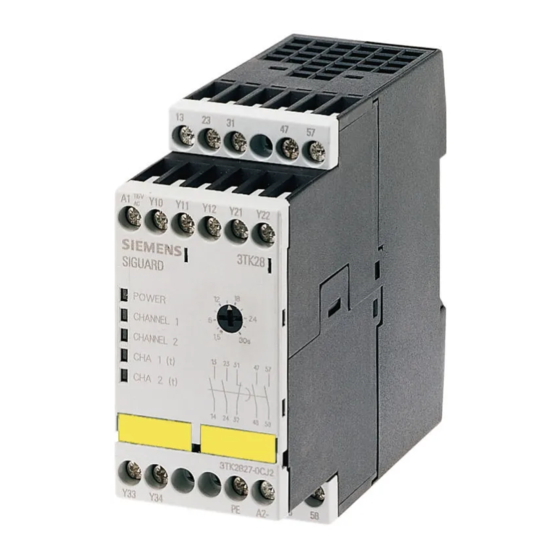
Page 84: Structure 3Tk2827/28
Description of the individual safety relays 3.6 3TK28 safety relays with relay enabling circuits 3.6.7.3 Structure 3TK2827/28 Front view Meaning ① Display LEDs ② Removable terminal blocks ③ Time setting ④ Labels 3.6.7.4 Terminal assignment Terminal Description Y10; Y11 Channel 1, (1-channel) Y11;... -
Page 85: Display Of The Operating State
Description of the individual safety relays 3.6 3TK28 safety relays with relay enabling circuits 3.6.7.5 Display of the operating state The operating state and functioning of the device are indicated by five LEDs: ● POWER ● CHANNEL 1 ● CHANNEL 2 ●... -
Page 86: State Diagrams 3Tk2827 / 3Tk2828
Description of the individual safety relays 3.6 3TK28 safety relays with relay enabling circuits 3.6.7.6 State diagrams 3TK2827 / 3TK2828 Figure 3-31 State diagram 3TK2827 (monitored start) Figure 3-32 State diagram 3TK2828 (Autostart) 3TK28 safety relays Manual, 07/2016, NEB926157502000/RS-AB/003... -
Page 87: Technical Data 3Tk2827 / 3Tk2828
Description of the individual safety relays 3.6 3TK28 safety relays with relay enabling circuits 3.6.7.7 Technical data 3TK2827 / 3TK2828 Technical data 3TK2827 3TK2827-.A... 3TK2827-.B... EMC emitted interference EN 60947-5-1 Item designation according to DIN 40719 extendable after IEC 204-2 •... - Page 88 Description of the individual safety relays 3.6 3TK28 safety relays with relay enabling circuits 3TK2827-.A... 3TK2827-.B... Design of the electrical connection jumper socket Switching capacity current — at AC-15 at 24 V • of the NO contacts of the relay outputs •...
- Page 89 Description of the individual safety relays 3.6 3TK28 safety relays with relay enabling circuits 3TK2827-.A... 3TK2827-.B... Product function automatic start • rotation speed monitoring • laser scanner monitoring • light grid monitoring • light barrier monitoring • magnetic switch monitoring Normally closed contact-Normally •...
- Page 90 Description of the individual safety relays 3.6 3TK28 safety relays with relay enabling circuits Technical data 3TK2828 3TK2828-.A... 3TK2828-.B... EMC emitted interference EN 60947-5-1 Item designation according to DIN 40719 extendable after IEC 204-2 • according to IEC 750 according to DIN EN 61346-2 •...
- Page 91 Description of the individual safety relays 3.6 3TK28 safety relays with relay enabling circuits 3TK2828-.A... 3TK2828-.B... Design of the electrical connection jumper socket Switching capacity current — at AC-15 at 24 V • of the NO contacts of the relay outputs •...
- Page 92 Description of the individual safety relays 3.6 3TK28 safety relays with relay enabling circuits 3TK2828-.A... 3TK2828-.B... Product function automatic start • rotation speed monitoring • laser scanner monitoring • light grid monitoring • light barrier monitoring • magnetic switch monitoring Normally closed contact- •...
-
Page 93: Connection Examples 3Tk2827 / 3Tk2828
Description of the individual safety relays 3.6 3TK28 safety relays with relay enabling circuits 3.6.7.8 Connection examples 3TK2827 / 3TK2828 Figure 3-33 Monitored start (1-channel) Figure 3-34 Monitored start (2-channel) 3TK28 safety relays Manual, 07/2016, NEB926157502000/RS-AB/003... - Page 94 Description of the individual safety relays 3.6 3TK28 safety relays with relay enabling circuits Figure 3-35 Autostart (1-channel) Figure 3-36 Autostart (2-channel) 3TK28 safety relays Manual, 07/2016, NEB926157502000/RS-AB/003...
- Page 95 Description of the individual safety relays 3.6 3TK28 safety relays with relay enabling circuits Figure 3-37 Grounding Note It is not necessary to connect the PE terminal for the device to function. For this reason, we recommend that you do not wire this terminal.
-
Page 96: 3Tk2830 Expansion Unit
Applications Applications of 3TK2830 expansion unit The 3TK2830 is used to expand the enabling circuits. You can use it together with all 3TK28 basic units. The maximum achievable performance level PL / Cat. in accordance with DIN EN ISO 13849-1, or SILCL in accordance with IEC 62061 is equivalent to the performance level PL / Cat. -
Page 97: Structure 3Tk2830
Description of the individual safety relays 3.6 3TK28 safety relays with relay enabling circuits 3.6.8.3 Structure 3TK2830 Front view Meaning ① Display LEDs ② Removable terminal blocks ③ Labels 3.6.8.4 Terminal assignment Terminal Description 13 - 14 Enabling circuit 1, (NO) -
Page 98: Display Of The Operating State
Description of the individual safety relays 3.6 3TK28 safety relays with relay enabling circuits 3.6.8.5 Display of the operating state The operating state and functioning of the device are indicated by two LEDs: ● CHANNEL 1 ● CHANNEL 2 Operating states of 3TK2830... -
Page 99: Technical Data 3Tk2830
Description of the individual safety relays 3.6 3TK28 safety relays with relay enabling circuits 3.6.8.7 Technical data 3TK2830 3TK2830-.A... 3TK2830-.C... EMC emitted interference EN 60947-5-1 Item designation according to DIN 40719 extendable after IEC 204-2 according • to IEC 750 according to DIN EN 61346-2 •... - Page 100 Description of the individual safety relays 3.6 3TK28 safety relays with relay enabling circuits 3TK2830-.A... 3TK2830-.C... Design of the electrical connection jumper socket Switching capacity current — at AC-15 at 24 V • of the NO contacts of the relay outputs •...
- Page 101 Description of the individual safety relays 3.6 3TK28 safety relays with relay enabling circuits 3TK2830-.A... 3TK2830-.C... Product function automatic start • rotation speed monitoring • laser scanner monitoring • light grid monitoring • light barrier monitoring • magnetic switch monitoring Normally closed contact-Normally •...
-
Page 102: Connection Examples 3Tk2830
Description of the individual safety relays 3.6 3TK28 safety relays with relay enabling circuits 3.6.8.8 Connection examples 3TK2830 Figure 3-39 EMERGENCY STOP Figure 3-40 EMERGENCY STOP with time delay 3TK28 safety relays Manual, 07/2016, NEB926157502000/RS-AB/003... -
Page 103: 3Tk2834 Two-Hand Control Device
Description of the individual safety relays 3.6 3TK28 safety relays with relay enabling circuits 3.6.9 3TK2834 two-hand control device 3.6.9.1 Applications Applications of the 3TK2834 two-hand control device The 3TK2834 two-hand control device is suitable for installation in controllers for the following presses: ●... -
Page 104: Structure 3Tk2834
Description of the individual safety relays 3.6 3TK28 safety relays with relay enabling circuits 3.6.9.3 Structure 3TK2834 Front view Meaning ① Display LEDs ② Removable terminal blocks ③ Labels 3.6.9.4 Terminal assignment Terminal Description 13; 14 Enabling circuit 1, (NO) 23;... -
Page 105: Display Of The Operating State
Description of the individual safety relays 3.6 3TK28 safety relays with relay enabling circuits 3.6.9.5 Display of the operating state The operating state and functioning of the device are indicated by five LEDs: ● POWER ● S 1 ON ● S 2 ON ●... -
Page 106: Technical Data 3Tk2834
Description of the individual safety relays 3.6 3TK28 safety relays with relay enabling circuits 3.6.9.6 Technical data 3TK2834 3TK2834-.A... 3TK2834-.B... EMC emitted interference EN 60947-5-1 Item designation according to DIN 40719 extendable after IEC 204-2 • according to IEC 750 according to DIN EN 61346-2 •... - Page 107 Description of the individual safety relays 3.6 3TK28 safety relays with relay enabling circuits 3TK2834-.A... 3TK2834-.B... Design of the electrical connection jumper socket Breaking capacity current at AC-15 at 24 V — Switching capacity current of the NO contacts of the relay...
- Page 108 Description of the individual safety relays 3.6 3TK28 safety relays with relay enabling circuits 3TK2834-.A... 3TK2834-.B... Product function automatic start • rotation speed monitoring • laser scanner monitoring • light grid monitoring • light barrier monitoring • magnetic switch monitoring Normally closed contact- •...
-
Page 109: Connection Example
Description of the individual safety relays 3.6 3TK28 safety relays with relay enabling circuits 3.6.9.7 Connection example Figure 3-41 Two-hand 3TK28 safety relays Manual, 07/2016, NEB926157502000/RS-AB/003... -
Page 110: 3Tk28 Safety Relays With Solid-State Enabling Circuits
Description of the individual safety relays 3.7 3TK28 safety relays with solid-state enabling circuits 3TK28 safety relays with solid-state enabling circuits 3.7.1 3TK2840 safety relay 3.7.1.1 Applications Applications of the 3TK2840 safety relay You can use the 3TK2840 safety relay in EMERGENCY STOP devices according to DIN EN / IEC 60947-5-5 and in safety circuits according to DIN EN / IEC 60204-1, e.g. -
Page 111: Structure 3Tk2840
Description of the individual safety relays 3.7 3TK28 safety relays with solid-state enabling circuits 3.7.1.3 Structure 3TK2840 Front view Meaning ① Display LEDs ② Removable terminal blocks ③ Labels 3.7.1.4 Terminal assignment Terminal Description Y11; Y12 Channel 1, EMERGENCY STOP or position switch Y21;... -
Page 112: Display Of The Operating State
Description of the individual safety relays 3.7 3TK28 safety relays with solid-state enabling circuits 3.7.1.5 Display of the operating state The operating state and functioning of the device are indicated by three LEDs: ● POWER ● RUN ● FAULT Operating states of 3TK2840... -
Page 113: State Diagrams 3Tk2840
Description of the individual safety relays 3.7 3TK28 safety relays with solid-state enabling circuits 3.7.1.6 State diagrams 3TK2840 Figure 3-42 State diagram 3TK2840 autostart Figure 3-43 State diagram 3TK2840 monitored start 3TK28 safety relays Manual, 07/2016, NEB926157502000/RS-AB/003... -
Page 114: Technical Data 3Tk2840
Description of the individual safety relays 3.7 3TK28 safety relays with solid-state enabling circuits 3.7.1.7 Technical data 3TK2840 3TK2840-1B... 3TK2840-2B... EMC emitted interference EN 60947-5-1, EN 61000-6-2, EN 61000-6-4 Item designation according to DIN 40719 extendable after • IEC 204-2 according to IEC 750 according to DIN EN 61346-2 •... - Page 115 Description of the individual safety relays 3.7 3TK28 safety relays with solid-state enabling circuits 3TK2840-1B... 3TK2840-2B... Design of the input cascading-input/functional switching • feedback input • start input • Design of the electrical connection jumper socket Switching capacity current of semiconductor outputs...
-
Page 116: Connection Examples 3Tk2840
Description of the individual safety relays 3.7 3TK28 safety relays with solid-state enabling circuits 3.7.1.8 Connection examples 3TK2840 Figure 3-44 Autostart (2-channel) Figure 3-45 Monitored start (2-channel) 3TK28 safety relays Manual, 07/2016, NEB926157502000/RS-AB/003... - Page 117 Description of the individual safety relays 3.7 3TK28 safety relays with solid-state enabling circuits Figure 3-46 Autostart (1-channel) Figure 3-47 Monitored start (1-channel) 3TK28 safety relays Manual, 07/2016, NEB926157502000/RS-AB/003...
-
Page 118: 3Tk2841 Safety Relay
Description of the individual safety relays 3.7 3TK28 safety relays with solid-state enabling circuits 3.7.2 3TK2841 safety relay 3.7.2.1 Applications Applications of the 3TK2841 safety relay You can use the 3TK2841 safety relay in EMERGENCY STOP devices according to DIN EN / IEC 60947-5-5 and in safety circuits according to DIN EN / IEC 60204-1, e.g. with... -
Page 119: Structure 3Tk2841
Description of the individual safety relays 3.7 3TK28 safety relays with solid-state enabling circuits 3.7.2.3 Structure 3TK2841 Front view Meaning ① Display LEDs ② Removable terminal blocks ③ Labels 3.7.2.4 Terminal assignment Terminal Description Y11; Y12 Channel 1, EMERGENCY STOP or position switch Y21;... -
Page 120: Display Of The Operating State
Description of the individual safety relays 3.7 3TK28 safety relays with solid-state enabling circuits 3.7.2.5 Display of the operating state The operating state and functioning of the device are indicated by three LEDs: ● POWER ● RUN ● FAULT Operating states of 3TK2841... -
Page 121: State Diagrams 3Tk2841
Description of the individual safety relays 3.7 3TK28 safety relays with solid-state enabling circuits 3.7.2.6 State diagrams 3TK2841 Figure 3-48 State diagram 3TK2841 autostart Figure 3-49 State diagram 3TK2841 monitored start 3TK28 safety relays Manual, 07/2016, NEB926157502000/RS-AB/003... -
Page 122: Technical Data 3Tk2841
Description of the individual safety relays 3.7 3TK28 safety relays with solid-state enabling circuits 3.7.2.7 Technical data 3TK2841 3TK2841-1B... 3TK2841-2B... EMC emitted interference IEC 60947-5-1, IEC 60000-4-3, IEC 60000-4-5, IEC 60000-4-6 Item designation according to DIN 40719 extendable after IEC 204-2 •... - Page 123 Description of the individual safety relays 3.7 3TK28 safety relays with solid-state enabling circuits 3TK2841-1B... 3TK2841-2B... Design of the electrical connection jumper socket Switching capacity current of semiconductor outputs for enabling circuit for DC-13 at 24 V Type of voltage of the controlled supply voltage...
-
Page 124: Connection Examples 3Tk2841
Description of the individual safety relays 3.7 3TK28 safety relays with solid-state enabling circuits 3.7.2.8 Connection examples 3TK2841 Figure 3-50 Autostart (2-channel) Figure 3-51 Monitored start (2-channel) 3TK28 safety relays Manual, 07/2016, NEB926157502000/RS-AB/003... - Page 125 Description of the individual safety relays 3.7 3TK28 safety relays with solid-state enabling circuits Figure 3-52 Autostart (2-channel) without cross-circuit detection Figure 3-53 Monitored start (1-channel) 3TK28 safety relays Manual, 07/2016, NEB926157502000/RS-AB/003...
- Page 126 Description of the individual safety relays 3.7 3TK28 safety relays with solid-state enabling circuits Figure 3-54 Safety shutdown mat Figure 3-55 Cascading 3TK28 safety relays Manual, 07/2016, NEB926157502000/RS-AB/003...
-
Page 127: 3Tk2842 Safety Relay
Description of the individual safety relays 3.7 3TK28 safety relays with solid-state enabling circuits 3.7.3 3TK2842 safety relay 3.7.3.1 Applications Applications of the 3TK2842 safety relay You can use the 3TK2842 safety relay in EMERGENCY STOP devices according to DIN EN / IEC 60947-5-5 and in safety circuits according to DIN EN / IEC 60204-1, e.g. with... -
Page 128: Structure 3Tk2842
Description of the individual safety relays 3.7 3TK28 safety relays with solid-state enabling circuits 3.7.3.3 Structure 3TK2842 Front view Meaning ① Display LEDs ② Removable terminal blocks ③ Time setting ④ Labels 3.7.3.4 Terminal assignment Terminal Description Y11; Y12 Channel 1, EMERGENCY STOP or position switch Y21;... -
Page 129: Display Of The Operating State
Description of the individual safety relays 3.7 3TK28 safety relays with solid-state enabling circuits 3.7.3.5 Display of the operating state The operating state and functioning of the device are indicated by three LEDs: ● POWER ● RUN ● FAULT Operating states of 3TK2842... -
Page 130: State Diagrams 3Tk2842
Description of the individual safety relays 3.7 3TK28 safety relays with solid-state enabling circuits 3.7.3.6 State diagrams 3TK2842 Figure 3-56 State diagram 3TK2842 autostart Figure 3-57 State diagram 3TK2842 monitored start 3TK28 safety relays Manual, 07/2016, NEB926157502000/RS-AB/003... -
Page 131: Technical Data 3Tk2842
Description of the individual safety relays 3.7 3TK28 safety relays with solid-state enabling circuits 3.7.3.7 Technical data 3TK2842 3TK2842-1B... 3TK2842-2B... EMC emitted interference IEC 60947-5-1, IEC 60000-4-3, IEC 60000-4-5, IEC 60000-4-6 Item designation according to DIN 40719 extendable after IEC 204-2 •... - Page 132 Description of the individual safety relays 3.7 3TK28 safety relays with solid-state enabling circuits 3TK2842-1B... 3TK2842-2B... Design of the input cascading-input/functional switching • feedback input • start input • Design of the electrical connection jumper socket Switching capacity current of semiconductor outputs for...
-
Page 133: Connection Examples 3Tk2842
Description of the individual safety relays 3.7 3TK28 safety relays with solid-state enabling circuits 3.7.3.8 Connection examples 3TK2842 ① Converter Figure 3-58 Protective door monitoring, autostart (2-channel) ① Converter Figure 3-59 EMERGENCY STOP, monitored start (2-channel) 3TK28 safety relays Manual, 07/2016, NEB926157502000/RS-AB/003... - Page 134 Description of the individual safety relays 3.7 3TK28 safety relays with solid-state enabling circuits ① Converter Figure 3-60 EMERGENCY STOP, monitored start (1-channel) ① Frequency converter without safety function Figure 3-61 Light array monitoring, (2-channel) without cross-circuit detection 3TK28 safety relays...
- Page 135 Description of the individual safety relays 3.7 3TK28 safety relays with solid-state enabling circuits ① Converter Figure 3-62 Safety shutdown mat, autostart (2-channel) ① Converter Figure 3-63 Cascading, EMERGENCY STOP + protective door monitoring, (2-channel) 3TK28 safety relays Manual, 07/2016, NEB926157502000/RS-AB/003...
-
Page 136: 3Tk28 Safety Relays With Contactor Relay Enabling Circuits
Description of the individual safety relays 3.8 3TK28 safety relays with contactor relay enabling circuits 3TK28 safety relays with contactor relay enabling circuits 3.8.1 3TK2805 / 3TK2806 safety relays 3.8.1.1 Applications The 3TK2805 / 3TK2806 contactor safety combinations are used in EMERGENCY STOP circuits and in circuits for monitoring protective equipment, such as safety guards. -
Page 137: Structure 3Tk2805/06
Description of the individual safety relays 3.8 3TK28 safety relays with contactor relay enabling circuits 3.8.1.3 Structure 3TK2805/06 Front view Meaning ① Display LEDs ② Terminal blocks ③ Labels 3.8.1.4 Terminal assignment Terminal Description X1 ... X6 Control connections 13 - 14... -
Page 138: Display Of The Operating States
Description of the individual safety relays 3.8 3TK28 safety relays with contactor relay enabling circuits 3.8.1.5 Display of the operating states Operating states of 3TK2805/06 "POWER" indicates that the device is energized. "CHANNEL 1" and "CHANNEL 2" light up if the ON button has been operated and the contacts of the EMERGENCY STOP button or the position switch are closed. -
Page 139: Technical Specifications 3Tk2805/ 3Tk2806
Description of the individual safety relays 3.8 3TK28 safety relays with contactor relay enabling circuits 3.8.1.7 Technical specifications 3TK2805/ 3TK2806 Ambient temperature °C -55 ... +80 during storage • -25 ... +55 during operation • Classification Type A Rated control supply voltage 24 V AC/DC;... -
Page 140: Connection Examples 3Tk2805/ 3Tk2806
Description of the individual safety relays 3.8 3TK28 safety relays with contactor relay enabling circuits 3.8.1.8 Connection examples 3TK2805/ 3TK2806 Connection examples 3TK2805 Figure 3-65 Monitored start; EMERGENCY STOP (2-channel) 3TK28 safety relays Manual, 07/2016, NEB926157502000/RS-AB/003... - Page 141 Description of the individual safety relays 3.8 3TK28 safety relays with contactor relay enabling circuits Connection examples 3TK2806 Figure 3-66 Autostart; protective door (2-channel) Figure 3-67 Autostart; protective door (1-channel) 3TK28 safety relays Manual, 07/2016, NEB926157502000/RS-AB/003...
-
Page 142: 3Tk2850 / 3Tk2851 / 3Tk2852 Safety Relay
Description of the individual safety relays 3.8 3TK28 safety relays with contactor relay enabling circuits 3.8.2 3TK2850 / 3TK2851 / 3TK2852 safety relay 3.8.2.1 Applications Applications of the 3TK285 safety combination You can use the 3TK285 safety combination in EMERGENCY STOP devices according to DIN EN / IEC 60947-5-5 and in safety circuits according to DIN EN / IEC 60204-1, e.g. -
Page 143: Structure 3Tk285
Description of the individual safety relays 3.8 3TK28 safety relays with contactor relay enabling circuits 3.8.2.3 Structure 3TK285 Front view Meaning ① Removable terminal block ② Display LEDs ③ Terminal blocks ④ Labels 3TK28 safety relays Manual, 07/2016, NEB926157502000/RS-AB/003... -
Page 144: Terminal Assignment
Description of the individual safety relays 3.8 3TK28 safety relays with contactor relay enabling circuits 3.8.2.4 Terminal assignment Terminal Description Y11; Y12 Channel 1, EMERGENCY STOP or position switch Y21; Y22 Channel 2, EMERGENCY STOP or position switch Parameterization "single-channel sensor connection"... -
Page 145: Display Of The Operating State
Description of the individual safety relays 3.8 3TK28 safety relays with contactor relay enabling circuits 3.8.2.5 Display of the operating state The operating state and functioning of the device are indicated by three LEDs: ● POWER ● RUN ● FAULT... -
Page 146: State Diagrams 3Tk2850 / 3Tk2851 / 3Tk2852
Description of the individual safety relays 3.8 3TK28 safety relays with contactor relay enabling circuits 3.8.2.6 State diagrams 3TK2850 / 3TK2851 / 3TK2852 For contact units, see Chapter: Terminal assignment (Page 144) Figure 3-69 State diagram 3TK2850 / 3TK2851 / 3TK2852 autostart... -
Page 147: Technical Data 3Tk2850 / 3Tk2851 / 3Tk2852
Description of the individual safety relays 3.8 3TK28 safety relays with contactor relay enabling circuits 3.8.2.7 Technical data 3TK2850 / 3TK2851 / 3TK2852 Technical data 3TK2850 3TK2850-.A... 3TK2850-.B... EMC emitted interference IEC 60947-5-1, IEC 60000-4-3, IEC 60000-4-5, IEC 60000-4-6 Item designation according to DIN 40719 extendable after IEC 204-2 •... - Page 148 Description of the individual safety relays 3.8 3TK28 safety relays with contactor relay enabling circuits 3TK2850-.A... 3TK2850-.B... Design of the electrical connection jumper socket Switching capacity current — at AC-15 at 24 V • of the NO contacts of the relay outputs •...
- Page 149 Description of the individual safety relays 3.8 3TK28 safety relays with contactor relay enabling circuits 3TK2850-.A... 3TK2850-.B... Product function automatic start • rotation speed monitoring • laser scanner monitoring • light grid monitoring • light barrier monitoring • magnetic switch monitoring Normally closed contact- •...
- Page 150 Description of the individual safety relays 3.8 3TK28 safety relays with contactor relay enabling circuits Technical data 3TK2851 3TK2851-.A... 3TK2851-.B... EMC emitted interference IEC 60947-5-1, IEC 60000-4-3, IEC 60000-4-5, IEC 60000-4-6 Item designation according to DIN 40719 extendable after IEC 204-2 •...
- Page 151 Description of the individual safety relays 3.8 3TK28 safety relays with contactor relay enabling circuits 3TK2851-.A... 3TK2851-.B... Design of the electrical connection jumper socket Switching capacity current — at AC-15 at 24 V • of the NO contacts of the relay outputs •...
- Page 152 Description of the individual safety relays 3.8 3TK28 safety relays with contactor relay enabling circuits 3TK2851-.A... 3TK2851-.B... Product function automatic start • rotation speed monitoring • laser scanner monitoring • light grid monitoring • light barrier monitoring • magnetic switch monitoring Normally closed contact- •...
- Page 153 Description of the individual safety relays 3.8 3TK28 safety relays with contactor relay enabling circuits Technical data 3TK2852 3TK2852-.A... 3TK2852-.B... EMC emitted interference IEC 60947-5-1, IEC 60000-4-3, IEC 60000-4-5, IEC 60000-4-6 Item designation according to DIN 40719 extendable after IEC 204-2 •...
- Page 154 Description of the individual safety relays 3.8 3TK28 safety relays with contactor relay enabling circuits 3TK2852-.A... 3TK2852-.B... Design of the electrical connection jumper socket Switching capacity current — at AC-15 at 24 V • of the NO contacts of the relay outputs •...
- Page 155 Description of the individual safety relays 3.8 3TK28 safety relays with contactor relay enabling circuits 3TK2852-.A... 3TK2852-.B... Product function automatic start • rotation speed monitoring • laser scanner monitoring • light grid monitoring • light barrier monitoring • magnetic switch monitoring Normally closed contact- •...
-
Page 156: Connection Examples 3Tk2850 / 3Tk2851 / 3Tk2852
Description of the individual safety relays 3.8 3TK28 safety relays with contactor relay enabling circuits 3.8.2.8 Connection examples 3TK2850 / 3TK2851 / 3TK2852 For contact units, see Chapter: Terminal assignment (Page 144) Figure 3-71 Autostart (2-channel) Figure 3-72 Autostart (1-channel) - Page 157 Description of the individual safety relays 3.8 3TK28 safety relays with contactor relay enabling circuits Figure 3-73 Monitored start (2-channel) Figure 3-74 Monitored start (1-channel) 3TK28 safety relays Manual, 07/2016, NEB926157502000/RS-AB/003...
-
Page 158: 3Tk2853 Safety Relay
Description of the individual safety relays 3.8 3TK28 safety relays with contactor relay enabling circuits 3.8.3 3TK2853 safety relay 3.8.3.1 Applications Applications of the 3TK2853 safety combination You can use the 3TK2853 safety combination in EMERGENCY STOP devices according to DIN EN / IEC 60947-5-5 and in safety circuits according to DIN EN / IEC 60204-1, e.g. -
Page 159: Structure 3Tk2853
Description of the individual safety relays 3.8 3TK28 safety relays with contactor relay enabling circuits 3.8.3.3 Structure 3TK2853 Front view Meaning ① Removable terminal block ② Display LEDs ③ Terminal blocks ④ Labels 3TK28 safety relays Manual, 07/2016, NEB926157502000/RS-AB/003... -
Page 160: Terminal Assignment
Description of the individual safety relays 3.8 3TK28 safety relays with contactor relay enabling circuits 3.8.3.4 Terminal assignment Terminal Description Y11; Y12 Channel 1, EMERGENCY STOP or position switch Y21; Y22 Channel 2, EMERGENCY STOP or position switch with / without cross-circuit detection Parameterization "single-channel sensor connection"... -
Page 161: Display Of The Operating State
Description of the individual safety relays 3.8 3TK28 safety relays with contactor relay enabling circuits 3.8.3.5 Display of the operating state The operating state and functioning of the device are indicated by three LEDs: ● POWER ● RUN ● FAULT... -
Page 162: State Diagrams 3Tk2853
Description of the individual safety relays 3.8 3TK28 safety relays with contactor relay enabling circuits 3.8.3.6 State diagrams 3TK2853 For contact units, see Chapter: Terminal assignment (Page 160) Figure 3-76 State diagram 3TK2853 autostart Figure 3-77 State diagram 3TK2853 monitored start... -
Page 163: Technical Data 3Tk2853
Description of the individual safety relays 3.8 3TK28 safety relays with contactor relay enabling circuits 3.8.3.7 Technical data 3TK2853 3TK2853-2B... 3TK2853-1B... EMC emitted interference IEC 60947-5-1, IEC 60000-4-3, IEC 60000-4-5, IEC 60000-4-6 Item designation according to DIN 40719 extendable after IEC 204-2 •... - Page 164 Description of the individual safety relays 3.8 3TK28 safety relays with contactor relay enabling circuits 3TK2853-2B... 3TK2853-1B... Number of outputs as contact-affected switching element as NO contact safety-related as contact-affected switching element as NC contact for • reporting function instantaneous switching as contact-affected switching element as NO contact •...
- Page 165 Description of the individual safety relays 3.8 3TK28 safety relays with contactor relay enabling circuits 3TK2853-2B... 3TK2853-1B... Control supply voltage 1 for DC final rated value for DC rated value • Operating range factor control supply voltage rated value of the magnet coil at 50 Hz •...
-
Page 166: Connection Examples 3Tk2853
Description of the individual safety relays 3.8 3TK28 safety relays with contactor relay enabling circuits 3.8.3.8 Connection examples 3TK2853 For contact units, see Chapter: Terminal assignment (Page 160) Figure 3-78 Autostart (2-channel) 3TK28 safety relays Manual, 07/2016, NEB926157502000/RS-AB/003... - Page 167 Description of the individual safety relays 3.8 3TK28 safety relays with contactor relay enabling circuits Figure 3-79 Autostart (1-channel) Figure 3-80 Monitored start (2-channel) 3TK28 safety relays Manual, 07/2016, NEB926157502000/RS-AB/003...
- Page 168 Description of the individual safety relays 3.8 3TK28 safety relays with contactor relay enabling circuits Figure 3-81 Monitored start (1-channel) Figure 3-82 Light array monitoring (2-channel) without cross-circuit detection 3TK28 safety relays Manual, 07/2016, NEB926157502000/RS-AB/003...
- Page 169 Description of the individual safety relays 3.8 3TK28 safety relays with contactor relay enabling circuits Figure 3-83 Cascading 3TK28 safety relays Manual, 07/2016, NEB926157502000/RS-AB/003...
- Page 170 Description of the individual safety relays 3.8 3TK28 safety relays with contactor relay enabling circuits Figure 3-84 without functional operation Figure 3-85 with isolated contact, functionally operated Figure 3-86 with non-isolated contact, functionally operated 3TK28 safety relays Manual, 07/2016, NEB926157502000/RS-AB/003...
-
Page 171: 3Tk2856 / 3Tk2857 Safety Relays
3.8.4.1 Applications Applications of 3TK2856/57 expansion units You can use the 3TK2856/57 expansion units in conjunction with all 3TK28/3RA7 basic units. It is used to expand the enabling circuits. The maximum achievable performance level PL / Cat. in accordance with DIN EN ISO 13849-1, or SILCL in accordance with IEC 62061 is equivalent to the PL / Cat. -
Page 172: Structure 3Tk2856/57
Description of the individual safety relays 3.8 3TK28 safety relays with contactor relay enabling circuits 3.8.4.3 Structure 3TK2856/57 Front view Meaning ① Removable terminal block ② Display LEDs ③ Terminal blocks ④ Labels 3TK28 safety relays Manual, 07/2016, NEB926157502000/RS-AB/003... -
Page 173: Terminal Assignment
Description of the individual safety relays 3.8 3TK28 safety relays with contactor relay enabling circuits 3.8.4.4 Terminal assignment Terminal Description Cascade input Safe solid-state output (24V DC / 1A) Power supply for external switches Input for functional switching 13; 14... -
Page 174: Display Of The Operating State
Description of the individual safety relays 3.8 3TK28 safety relays with contactor relay enabling circuits 3.8.4.5 Display of the operating state The operating state and functioning of the device are indicated by three LEDs: ● POWER ● RUN ● FAULT... -
Page 175: State Diagrams 3Tk2856 / 3Tk2857
Description of the individual safety relays 3.8 3TK28 safety relays with contactor relay enabling circuits 3.8.4.6 State diagrams 3TK2856 / 3TK2857 For contact units, see Chapter: Terminal assignment (Page 173) Figure 3-88 State diagram 3TK2856 Figure 3-89 State diagram 3TK2857... -
Page 176: Technical Data 3Tk2856 / 3Tk2857
Description of the individual safety relays 3.8 3TK28 safety relays with contactor relay enabling circuits 3.8.4.7 Technical data 3TK2856 / 3TK2857 3TK2856-.B... 3TK2857-.B... EMC emitted interference IEC 60947-5-1, IEC 60000-4-3, IEC 60000-4-5, IEC 60000-4-6 Item designation according to DIN 40719 extendable after IEC 204-2 •... - Page 177 Description of the individual safety relays 3.8 3TK28 safety relays with contactor relay enabling circuits 3TK2856-.B... 3TK2857-.B... Number of outputs as contact-affected switching element as NO contact safety-related as contact-affected switching element as NC contact for • reporting function instantaneous switching as contact-affected switching element as NO contact •...
- Page 178 Description of the individual safety relays 3.8 3TK28 safety relays with contactor relay enabling circuits 3TK2856-.B... 3TK2857-.B... Control supply voltage 1 for DC final rated value for DC rated value • Operating range factor control supply voltage rated value of the magnet coil at 50 Hz •...
-
Page 179: Connection Examples 3Tk2856 / 3Tk2857
Description of the individual safety relays 3.8 3TK28 safety relays with contactor relay enabling circuits 3.8.4.8 Connection examples 3TK2856 / 3TK2857 For contact units, see Chapter: Terminal assignment (Page 173) Figure 3-90 3TK2823 expanded with 3TK2856/57 Figure 3-91 3TK2841 expanded with 3TK2856/57... - Page 180 Description of the individual safety relays 3.8 3TK28 safety relays with contactor relay enabling circuits Figure 3-92 3TK2853 expanded with 3TK2856/57 Figure 3-93 without functional operation 3TK28 safety relays Manual, 07/2016, NEB926157502000/RS-AB/003...
- Page 181 Description of the individual safety relays 3.8 3TK28 safety relays with contactor relay enabling circuits Figure 3-94 with isolated contact, functionally operated Figure 3-95 with non-isolated contact, functionally operated 3TK28 safety relays Manual, 07/2016, NEB926157502000/RS-AB/003...
- Page 182 Description of the individual safety relays 3.8 3TK28 safety relays with contactor relay enabling circuits 3TK28 safety relays Manual, 07/2016, NEB926157502000/RS-AB/003...
-
Page 183: Mounting
Mounting Warning notices Warning notices before installation, wiring, and commissioning WARNING Hazardous voltage! Can cause electric shock and burns. Turn off and lock out all power supplying this device before working on this device. 3TK28 safety relays Manual, 07/2016, NEB926157502000/RS-AB/003... -
Page 184: Mounting The Device On A Din Rail
For installation of the 3TK2820, see Section: Mounting the device on a DIN rail (Page 36) Step Operating instruction Figure Hang the back of the device onto the upper edge of the DIN rail Press the lower half of the device against the DIN rail until the device engages 3TK28 safety relays Manual, 07/2016, NEB926157502000/RS-AB/003... -
Page 185: Mounting The Device On A Level Surface
● Two properly executed drill holes with thread or plug on the level surface For details of the distances between the drilled holes, please refer to the relevant dimension drawings in the chapter "Dimension drawings 3TK28 (Page 195)". ● Two screws with a maximum thread diameter of 4.8 mm ●... -
Page 186: Disassembling The Device
Pull the device down until the lower half can be pulled away from the DIN rail. Pull the lower half of the device away from the DIN rail. Lift the device from the upper edge of the DIN rail. 3TK28 safety relays Manual, 07/2016, NEB926157502000/RS-AB/003... - Page 187 Disassembling the device from a level surface Step Operating instruction Figure Hold the device firmly. Unscrew the cap screws. Lift the device from the level surface. Remove the securing brackets from the device. See also Disassembling the device (Page 37) 3TK28 safety relays Manual, 07/2016, NEB926157502000/RS-AB/003...
- Page 188 Mounting 4.4 Disassembling the device 3TK28 safety relays Manual, 07/2016, NEB926157502000/RS-AB/003...
-
Page 189: Connection
1 x 0.5 … 2.5 mm 2 x 0.25 … 1.5 mm 2 x 0.5 … 1.5 mm Flexible cable Not allowed Maximum number of cables x cable cross-section: 2 x 0.25 … 1.5 mm 3TK28 safety relays Manual, 07/2016, NEB926157502000/RS-AB/003... -
Page 190: Connecting Terminal Blocks
Hold the cable in the screw-type terminal. Tighten the screw of the terminal in which the cable is inserted. Pull on the cable to ensure it is screwed tight. 3TK28 safety relays Manual, 07/2016, NEB926157502000/RS-AB/003... - Page 191 Insert the cable into the oval opening as far as it will go. Hold the cable in the spring-loaded terminal. Remove the screwdriver. Pull on the cable to ensure it is tight. See also Connecting terminal blocks (Page 39) 3TK28 safety relays Manual, 07/2016, NEB926157502000/RS-AB/003...
-
Page 192: Disconnecting
Insert a flat-head screwdriver between the clip ① of the terminal block and the front panel ② Pull the terminal block out to the front Lift the terminal block out of the mechanically ③ coded guiderail of the device 3TK28 safety relays Manual, 07/2016, NEB926157502000/RS-AB/003... - Page 193 Insert the flat-head screwdriver into the square opening of the spring-loaded terminal until it engages. Please observe a 10° horizontal angular deviation of the screwdriver to the oval opening. Remove the cable from the oval opening. Remove the screwdriver. 3TK28 safety relays Manual, 07/2016, NEB926157502000/RS-AB/003...
-
Page 194: Plugging In Terminal Blocks
Insert the removable terminal block into the ① mechanically coded guiderail of the device Slide the removable terminal block back until it audibly engages. Check that the clip of the removable terminal ② block closes flush with the front panel 3TK28 safety relays Manual, 07/2016, NEB926157502000/RS-AB/003... -
Page 195: Dimension Drawings
Dimension drawings Dimension drawings 3TK28 All dimensions in mm Figure 6-1 3TK2810/25/26/27/28/34/45 screw-type Figure 6-2 3TK2810/25/26/27/28/34/45 spring-loaded 3TK28 safety relays Manual, 07/2016, NEB926157502000/RS-AB/003... - Page 196 Dimension drawings 6.1 Dimension drawings 3TK28 Figure 6-3 3TK2820 3TK2820-1... 103,6 3TK2820-2... 111,2 ≥ 5 ≥ 5 ≥ 5 3TK28 safety relays Manual, 07/2016, NEB926157502000/RS-AB/003...
- Page 197 Dimension drawings 6.1 Dimension drawings 3TK28 Figure 6-4 3TK2821/22/23/24/30 screw-type Figure 6-5 3TK2821/22/23/24/30 spring-loaded 3TK28 safety relays Manual, 07/2016, NEB926157502000/RS-AB/003...
- Page 198 Dimension drawings 6.1 Dimension drawings 3TK28 Figure 6-6 3TK2840/41/42 screw-type Figure 6-7 3TK2840/41/42 spring-loaded 3TK28 safety relays Manual, 07/2016, NEB926157502000/RS-AB/003...
- Page 199 Dimension drawings 6.1 Dimension drawings 3TK28 Figure 6-8 3TK2850/51 screw-type Figure 6-9 3TK2850/51 spring-loaded 3TK28 safety relays Manual, 07/2016, NEB926157502000/RS-AB/003...
- Page 200 Dimension drawings 6.1 Dimension drawings 3TK28 Figure 6-10 3TK2852 screw-type Figure 6-11 3TK2852 spring-loaded 3TK28 safety relays Manual, 07/2016, NEB926157502000/RS-AB/003...
- Page 201 Dimension drawings 6.1 Dimension drawings 3TK28 Figure 6-12 3TK2853 screw-type Figure 6-13 3TK2853 spring-loaded 3TK28 safety relays Manual, 07/2016, NEB926157502000/RS-AB/003...
- Page 202 Dimension drawings 6.1 Dimension drawings 3TK28 Figure 6-14 3TK2856 screw-type Figure 6-15 3TK2856 spring-loaded 3TK28 safety relays Manual, 07/2016, NEB926157502000/RS-AB/003...
- Page 203 Dimension drawings 6.1 Dimension drawings 3TK28 Figure 6-16 3TK2857 screw-type Figure 6-17 3TK2857 spring-loaded 3TK28 safety relays Manual, 07/2016, NEB926157502000/RS-AB/003...
- Page 204 Dimension drawings 6.1 Dimension drawings 3TK28 3TK28 safety relays Manual, 07/2016, NEB926157502000/RS-AB/003...
-
Page 205: Accessories
Accessories Accessories for 3TK28 The following accessories are available for the 3TK28 devices. Designation Article number Suitable for: Device identification labels 3RT1900-1SB20 3TK28 20 mm x 7 mm, pastel turquoise Labels 3RT1900-1SB60 3TK28 19 mm x 6 mm, pastel turquoise... - Page 206 Accessories 3TK28 safety relays Manual, 07/2016, NEB926157502000/RS-AB/003...