
Related Manuals for Bosch PM1-LISM6


Summary of Contents for Bosch PM1-LISM6
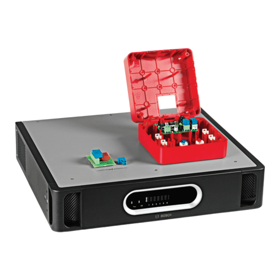
- Page 1 Loudspeakers Line Isolator System PM1-LISM6, PM1-LISS, PM1-LISD Installation and Operation Manual...
-
Page 3: Table Of Contents
Connect and test loudspeaker loop Configuration Master Unit settings 7.1.1 Voltage/ground selection 7.1.2 DIP switch settings Isolator Board settings Operation Master Unit (front panel) Master Unit (rear view) Commissioning Walk Test Bosch Security Systems B.V. Installation and Operation Manual 2014.03 | V1.1 |... - Page 4 Check the connectors and grounding 10.3 Perform a Walk Test Technical data 11.1 Master Unit 11.2 Isolator Board 11.3 End of line resistor 11.4 DC Blocking Board 11.5 Approvals 11.6 Compliance 2014.03 | V1.1 | Installation and Operation Manual Bosch Security Systems B.V.
-
Page 5: Safety
Electrical and Electronic Equipment Directive). To dispose of old electrical or electronic devices, you should use the return and collection systems put in place in the country concerned. Bosch Security Systems B.V. Installation and Operation Manual 2014.03 | V1.1 |... -
Page 6: About This Manual
For information on getting permission for reprints and excerpts, contact Bosch Security Systems B.V.. The content and illustrations are subject to change without prior notice. -
Page 7: Document History
Section 4.2.4, minor update. – Section 7.1.2, minor update. – Section 7.2, resistor value changed. – Section 11.1, minor update. – Section 11.2, minor update. – Section 11.5, minor update. Bosch Security Systems B.V. Installation and Operation Manual 2014.03 | V1.1 |... -
Page 8: Terminology Used In This Manual
Loudspeaker Line Referred to in this manual as “Master Unit” - main product of the Isolator System Master Loudspeakers Line Isolator System. (PM1-LISM6) 2014.03 | V1.1 | Installation and Operation Manual Bosch Security Systems B.V. - Page 9 Test mode for checking the loop by feeding the power and signal from one side of the loop only. Zone An area where the same signal is broadcast that can be separately addressed by the public address system. Bosch Security Systems B.V. Installation and Operation Manual 2014.03 | V1.1 |...
-
Page 10: System Overview
Jumper settings are provided to set the permissible loudspeaker power level (10, 36, 100 watt, or 10 watt with 20 kHz pilot tone filter), and other supervision settings. 2014.03 | V1.1 | Installation and Operation Manual Bosch Security Systems B.V. - Page 11 These functions can be configured with jumper settings. The Isolator Board can be mounted inside the included IP30 housing or in Bosch loudspeakers that have mounting provisions for loudspeaker or line supervision. A test button and LED indicator on the Isolator Board are used to check if the Isolator Board and loudspeaker cable (including polarity) are correctly connected.
-
Page 12: System Compatibility
(LBB4440/00, LBB4441/00, LBB4442/00, and LBB4443/00). The Loudspeakers Line Isolator System can be used in EN54-16 certified public address systems that need to comply to evacuation standards. 2014.03 | V1.1 | Installation and Operation Manual Bosch Security Systems B.V. -
Page 13: System Description
One or more loudspeakers are connected in a segment or segments. In this case a DC Blocking Board must be connected to each loudspeaker (maximum 20 watt loudspeaker load). See Installation option 3: Loudspeakers connected between Isolator Boards, page Bosch Security Systems B.V. Installation and Operation Manual 2014.03 | V1.1 |... -
Page 14: System Behavior
Short circuit inside a loudspeaker (after a – The system does not detect a loop fault. DC Blocking Board) – Loss of audio in the affected speaker. 2014.03 | V1.1 | Installation and Operation Manual Bosch Security Systems B.V. - Page 15 – After resolution of the fault, the fault recovery time is < 100 seconds. Bosch Security Systems B.V. Installation and Operation Manual 2014.03 | V1.1 |...
-
Page 16: Planning
DC Blocking Board Set of connectors System Prerequisites Make sure: – You have downloaded the latest version of the documentation from the Bosch website: www.boschsecurity.com – You have the manufacturer approved materials to install this equipment. – There is a mains power outlet of sufficient rating close to the intended location of the product(s). -
Page 17: General System Requirements
The maximum cable length is 1000 m (3281 ft) per loop. The public address system is a 100 volt constant voltage system (e.g. Bosch Plena, Bosch Praesideo). The power consumption of the loudspeakers is between 0 and 100 watts. -
Page 18: Praesideo System Requirements
If a PRS-4B125 amplifier is used, a DC Blocking Board or a capacitor and 33 ohm > 3 watt resistor must be used between the tap-off of the Isolator Board and the connected loudspeaker. 2014.03 | V1.1 | Installation and Operation Manual Bosch Security Systems B.V. -
Page 19: Loudspeaker/System Cable Requirements
When using installation option 1 or 2, with a 100 watt permissible load setting on the Isolator Board, a DC blocking capacitor of at least 22 µF must be used. The maximum permissible load on a DC Blocking Board is 20 watts. Bosch Security Systems B.V. Installation and Operation Manual 2014.03 | V1.1 |... -
Page 20: Installation Options
DC Blocking Board. An overload on the tap-off of the DC Blocking Board will not lead to a fault indication. See Installation option 3: Loudspeakers connected between Isolator Boards, page 25. 2014.03 | V1.1 | Installation and Operation Manual Bosch Security Systems B.V. -
Page 21: Installation Option 1: One Isolator Board For Each Loudspeaker
Short circuit in the main loop – No loss of audio. Short circuit in the tap-off – Not applicable for this installation option. Short circuits are handled as overloads. Bosch Security Systems B.V. Installation and Operation Manual 2014.03 | V1.1 |... - Page 22 Two or more faults on the main – Loss of audio between faults including the affected loop and/or tap-off tap-offs. – Audio artifacts may be present between Isolator Boards with the tap-off faults. 2014.03 | V1.1 | Installation and Operation Manual Bosch Security Systems B.V.
-
Page 23: Installation Option 2: Branch Of Loudspeakers Connected To An Isolator Board
The tap-off can be monitored for: – short circuits. – open circuits. – See Isolator Board settings, page 43. Loudspeaker – Loudspeaker connected to the DC Blocking Board tap-off connection. Bosch Security Systems B.V. Installation and Operation Manual 2014.03 | V1.1 |... - Page 24 Two or more faults on the main – Loss of audio between faults including affected tap- loop and/or tap-off. offs. – Audio artifacts may be present between Isolator Boards with the tap-off faults. 2014.03 | V1.1 | Installation and Operation Manual Bosch Security Systems B.V.
-
Page 25: Installation Option 3: Loudspeakers Connected Between Isolator Boards
DC blocking capacitor must be used instead – see Installation, page 28. The following table shows how the audio is affected in the system if installation option 3 is chosen: Bosch Security Systems B.V. Installation and Operation Manual 2014.03 | V1.1 |... - Page 26 DC Blocking Board affected DC Blocking Board tap-offs. tap-off – Audio artifacts may be present in segments that are isolated. See also – Configuration, page 41 – Installation, page 28 2014.03 | V1.1 | Installation and Operation Manual Bosch Security Systems B.V.
-
Page 27: Combining Installation Options
Isolator Board at a distance. – Whether or not a branch should be monitored for open circuits depends on local standards. See also – Configuration, page 41 Bosch Security Systems B.V. Installation and Operation Manual 2014.03 | V1.1 |... -
Page 28: Installation
Depending on the installation setup and type of loudspeaker, either an Isolator Board, DC Blocking Board, or DC blocking capacitor must be used. See Installation options, page 20. 2014.03 | V1.1 | Installation and Operation Manual Bosch Security Systems B.V. -
Page 29: Install Master Unit In 19-Inch Rack
Install an Isolator Board or DC Blocking Board in a housing Notice! Each Isolator Board is supplied with an IP30 rated housing. Alternatively the Isolator Board can be mounted in selected Bosch loudspeakers using the mounting provisions. Refer to the appropriate loudspeaker manual. Open the supplied housing. -
Page 30: Install An Isolator Board Or Dc Blocking Board In A Loudspeaker
(X2) of the last DC Blocking Board in the branch. Refer to DC Blocking Board, page 38. See also – Installation option 2: Branch of loudspeakers connected to an Isolator Board, page 23 2014.03 | V1.1 | Installation and Operation Manual Bosch Security Systems B.V. -
Page 31: Connections Indicators And Controls
For information on the preferred cable type and length that can be used with the Loudspeakers Line Isolator System, refer to: - System Prerequisites, page 16. - Technical data, page 54. Bosch Security Systems B.V. Installation and Operation Manual 2014.03 | V1.1 |... -
Page 32: Master Unit
Grounded Floating Caution Battery 24 / 48 V 4.5 A Max Risk of electric shock. Do not open Non-isolated input Avis Risque de choc electrique. Ne pas ouvrir 2014.03 | V1.1 | Installation and Operation Manual Bosch Security Systems B.V. - Page 33 This indication is active in Walk Test mode. This indicator lights up when the last segment is connected in reverse polarity. – See Master Unit indicators Master Unit (rear view), page 47. Bosch Security Systems B.V. Installation and Operation Manual 2014.03 | V1.1 |...
- Page 34 (chassis). – See Praesideo system requirements, page 18 and the Praesideo Installation and User Instructions. Power on/off – AC mains power switch. 2014.03 | V1.1 | Installation and Operation Manual Bosch Security Systems B.V.
- Page 35 Connections indicators and controls | en No. Item Description Mains inlet – AC mains input socket 115/230 VAC. Type plate – Plate containing information on product type and serial number. Bosch Security Systems B.V. Installation and Operation Manual 2014.03 | V1.1 |...
-
Page 36: Isolator Board
The board is powered correctly and the test button is pressed. Tap-off power 10 – Tap-off overload threshold is 10 watts, including a 20 kHz watts + Pilot tone pilot tone attenuation filter. filter (X7) 2014.03 | V1.1 | Installation and Operation Manual Bosch Security Systems B.V. - Page 37 – Tap-off connection to loudspeaker(s) X3+ – Tap-off connection to loudspeaker(s) X3- Warning! If there is a short/overload on the Isolator Board, the power resistors can get hot. Bosch Security Systems B.V. Installation and Operation Manual 2014.03 | V1.1 |...
-
Page 38: Dc Blocking Board
(X3) 100 volt – 2-pin removable screw connector (pin designation from left to loudspeaker tap-off right): connection – Tap-off connection to loudspeaker(s) X3+ – Tap-off connection to loudspeaker(s) X3- 2014.03 | V1.1 | Installation and Operation Manual Bosch Security Systems B.V. -
Page 39: Connect And Test Loudspeaker Loop
During installation, the Master Unit will correctly display a fault in the loop until the loop has been installed correctly. When the entire loop has been installed correctly, the fault LED will switch off within the fault recovery time. Bosch Security Systems B.V. Installation and Operation Manual 2014.03 | V1.1 |... - Page 40 After rectifying the problem, recheck the system. Set the Walk Test mode to off. See also – Installation options, page 20 2014.03 | V1.1 | Installation and Operation Manual Bosch Security Systems B.V.
-
Page 41: Configuration
Note: If no loop is enabled, all indications on the front of the Master Unit are off, including the mains and backup indication. Bosch Security Systems B.V. Installation and Operation Manual 2014.03 | V1.1 |... - Page 42 Battery – Backup fault reporting deactivated (LED supervision (default) and fault relay). – Backup fault reporting activated (LED and fault relay). See also – Master Unit, page 32 2014.03 | V1.1 | Installation and Operation Manual Bosch Security Systems B.V.
-
Page 43: Isolator Board Settings
2-pin jumper (X5) Maximum 36 W – This setting determines permissible load the overload detection level. Use this jumper setting if the loudspeaker load is between 10 watts and 36 watts. Bosch Security Systems B.V. Installation and Operation Manual 2014.03 | V1.1 |... - Page 44 3. 3-pin jumper Tap-off short – Can be used for (X401) circuit detection installation option 2. OFF (default) – Must be used for installation option 1 and 2014.03 | V1.1 | Installation and Operation Manual Bosch Security Systems B.V.
-
Page 45: Operation
– Backup power is present. – The Master Unit has no mains power and backup power is below 18 volts. – The battery supervision is set to OFF. Bosch Security Systems B.V. Installation and Operation Manual 2014.03 | V1.1 |... - Page 46 Maximum initialization time = 10 seconds after start up. – Loudspeaker loop initialization finished. – Loop is disabled. Walk Test mode Yellow – Walk Test is enabled. – Walk Test is disabled. 2014.03 | V1.1 | Installation and Operation Manual Bosch Security Systems B.V.
-
Page 47: Master Unit (Rear View)
– All segments are connected correctly, if Loop OK LED (3) is on. – Open circuit in the loop. – Loop is disabled. Note: This indication is immediate. Bosch Security Systems B.V. Installation and Operation Manual 2014.03 | V1.1 |... -
Page 48: Commissioning
Check the loop OK LED (3) on the rear panel of the Master Unit. If the loop OK LED is on, the connection is correct. Set the Walk Test mode to off. For problem solving during the Walk Test, refer to Troubleshooting, page 49. 2014.03 | V1.1 | Installation and Operation Manual Bosch Security Systems B.V. -
Page 49: Troubleshooting
PA system is turned off. – Check if the PA system is turned on. PA system not connected. – Check loudspeaker connections from the PA system to the Master Unit. Bosch Security Systems B.V. Installation and Operation Manual 2014.03 | V1.1 |... - Page 50 DC Blocking Board series with the or a 33 ohm resistor and loudspeaker. decoupling capacitor are used in series with the loudspeaker. 2014.03 | V1.1 | Installation and Operation Manual Bosch Security Systems B.V.
- Page 51 Isolator Board. – Check with known good loudspeaker. – Use a DC Blocking Board or a 33 ohm resistor and a decoupling capacitor in series with the loudspeaker. Bosch Security Systems B.V. Installation and Operation Manual 2014.03 | V1.1 |...
- Page 52 – Check connections and the first and last fault, settings at the first including tap-offs. The system defective location. will retry the loop every 15 to 35 seconds. 2014.03 | V1.1 | Installation and Operation Manual Bosch Security Systems B.V.
-
Page 53: Maintenance
Make sure all screw terminals and ground (PE) connections are fully tightened. 10.3 Perform a Walk Test Regularly perform a Walk Test, according to local regulation or contractual obligations. See Walk Test, page 48. Bosch Security Systems B.V. Installation and Operation Manual 2014.03 | V1.1 |... -
Page 54: Technical Data
500 W Frequency range 50 Hz – 20 kHz Max. sum blocking capacitance Max. sum blocking capacitance per loop 4700 µF Max sum blocking capacitance per tap-off 220 µF 2014.03 | V1.1 | Installation and Operation Manual Bosch Security Systems B.V. - Page 55 ≤ 10 Ω detected on primary output and return Fault isolation time ≤ 4 s (50 Isolator Boards or less per loop) Ground short < 50 kohm Figure 11.1: Battery power consumption 24 Vdc Bosch Security Systems B.V. Installation and Operation Manual 2014.03 | V1.1 |...
- Page 56 (+23 ºF to +131 ºF) Storage temperature -20 ºC to +70 ºC (-4 ºF to +158 ºF) Relative humidity 15% to 90% Air pressure 600 to 1100 hPa 2014.03 | V1.1 | Installation and Operation Manual Bosch Security Systems B.V.
-
Page 57: Isolator Board
(-4 ºF to +158 ºF) Relative humidity 15% to 90% Air pressure 600 to 1100 hPa 11.3 End of line resistor Electrical End of line resistor 47 kohm, > 0.5 W resistor Bosch Security Systems B.V. Installation and Operation Manual 2014.03 | V1.1 |... -
Page 58: Dc Blocking Board
EN 55103‑2, and EN 50130‑4 Maritime acc. to EN 60945 Evacuation acc. to EN 54‑16 11.6 Compliance Compliant for use as described in NEN2575, VDE0833, and BS5839 Evacuation acc. to EN 60849 2014.03 | V1.1 | Installation and Operation Manual Bosch Security Systems B.V. - Page 60 Bosch Security Systems B.V. Torenallee 49 5617 BA Eindhoven The Netherlands www.boschsecurity.com © Bosch Security Systems B.V., 2014...