Table of Contents
Advertisement
Quick Links
Advertisement
Table of Contents

Related Manuals for Beko CSM 63320 DSL


Summary of Contents for Beko CSM 63320 DSL
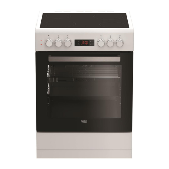
- Page 1 BARBAROS FS GOOD TIMER OVEN SERVICE MANUAL (4 ceran)
-
Page 2: Table Of Contents
1.COVER 2.INDEX 1. COVER 2.INDEX 1.COVER ............................2 3. SAFETY WARNING .......................... 4 3.1 G ............................4 ENERAL AFETY 3.2. S ........................4 AFETY FOR ONFİGURATİONS 3.3 I ........................5 NFORMATİONS FOR ONSUMER 4. TECHNICAL SPECIFICATIONS ......................6 5. PRODUCT ASSEMBLY/ ASSEMBLY RULES/ SETTINGS ............... 7 5.2 U .......................... - Page 3 10.2 L ............................38 AULT 10.2.1 Furnace is working but the oven does not illuminate ............... 38 10.2.2 Oven does not work,oven lamp does not light, ................. 39 10.3 T ..........................40 ERMOSTAT AULT 10.3.1 Furnace runs continuosly,the thermostat is not tripped............40 12.
-
Page 4: Safety Warning
3. SAFETY WARNING This section contains safety instructions that will help protect from risk of personal injury or property damage. Throughout this service manual the following symbols are used. Important information or useful hints about usage. Warning for hazardous situations with regard to life and property. Warning for electric shock. -
Page 5: Informations For Consumer
3.3 Informations for Consumer Product may be hot during the usage. Do not touch with hot parts ,inside the oven,heating components etc. .When the product is working it is hot so do not put combustable materials near the product. ... -
Page 6: Technical Specifications
4. TECHNICAL SPECIFICATIONS Please e-library of product specific technical specifications of the product by going under or see manusoft. -
Page 7: Product Assembly/ Assembly Rules/ Settings
5. PRODUCT ASSEMBLY/ ASSEMBLY RULES/ SETTINGS 5.1 Product Transportation To carry or move the product, do not use door or handle of the product. Door, handle or hinges can be harmed. Product should be carried by two person for safety of the product and ergonomics When the product is being carried or the product is being put to the ground, do not put it keenly, do not drag it and do... -
Page 8: Unpacking Product
5.2 Unpacking Product To consider product changing in the mounting process, please do not harm package, product and the product package when extracting. Extract package with a knife without harming top and bottom carton. Take the top carton. Take lathes on the product’s front and behind sides, like shown in below. -
Page 9: Controlling The Setup Place And Energy Sources
Take stripers which are left and right side of the products. Symbols on the package of the products and meaning of them; Do not carry Carry the product Carry with Preserve the product in this way by Do not step on Fragile barrow in from damp... - Page 10 • It can be used with cabinets on either side but in order to have a minimum distance of 400mm above hotplate level allow a side clearance of 65mm between the appliance and any wall, partition or tall cupboard. • It can also be used in a free standing position.
- Page 11 The appliance corresponds to device class 1, i.e. it may be placed with the rear and one side to kitchen walls, kitchen furniture or equipment of any size. The kitchen furniture or equipment on the other side may only be of the same size or smaller. Any kitchen furniture next to the appliance must be heat-resistant (100 °C min.).
-
Page 12: Control Of The Electrical Installation
5.3.2 Control of the electrical installation The following values for the control of electrical installation products with the product should be considered. Wattmeter used for control installations. Wattmeter Install product plug wattmetre. wattmeter insert the plug. Set the thermostat degree max. -
Page 13: Electrical Connection
Bring to the location you want to measure the commutator. Check that show the location of the few volts. 5.4 Electrical connection Before starting any work on the electrical installation, disconnect the product from the mains supply. Connect the product to a grounded outlet/line protected by a fuse of suitable capacity as stated in the "Technical specifications"... -
Page 14: Setting Foot Oven
Connection must comply with national regulations. The mains supply data must correspond to the data specified on the type label of the product.Open the front door to see the type label. Setting Foot Oven Goods stands on the plastic feet which is mounted 4 screw. -
Page 15: Use Of Products
6.USE OF PRODUCTS 6.1 Time settings Plug in the power cord and turn on the device fuse. The language setting of the clock setting before you need to do. NOTE: Each value you set, it is automatically saved when you exit the current menu. NOTE: Before using the oven, adjust the time 1 Setting key 2 Key lock icon... -
Page 16: Changing The Time Of Day
"+" Or "-" key to set the time of day by touching. After you adjust the time, touch or wait 4 seconds. symbol disappears and the clock is set. After the hour is set, by setting the thermostat knob to the desired location and function buttons;... - Page 17 Activate the symbol touching. '-' And '+' button to set the time of day with. After the clock setting, touch or wait 4 seconds.
-
Page 18: Brightness Adjustment
6.1.3 Brightness Adjustment 1 Setting key 2 Key lock icon 4 Alarm sound symbol 5 Economic mode symbol 6 Up button 7 Down button 8 time zone symbol 9 Alarm symbol 10 Cooking end time symbol 11 Cooking time symbol 12 Program key 11 Cooking time symbol 12 Program key... -
Page 19: Making The Oven Using The Clock And Cooking Times
6.1.4 Making the oven Using the clock and cooking times; 1 Setting key 2 Key lock icon 4 Alarm sound symbol 5 Economic mode symbol 6 Up button 7 Down button 8 time zone symbol 9 Alarm symbol 10 Cooking end time symbol 11 Cooking time symbol 12 Program key 11 Cooking time symbol... - Page 20 Tap on the screen until the symbol for the cooking time. Set the cooking time using the buttons. »Continuous time zone symbol and the symbol will appear on the screen after the cooking time is set. »Cooking begins when the cooking time countdown and time zone display will illuminate all parts of the symbol.
- Page 21 Touch the symbol on the screen until the end of cooking time. »After the cooking end time is set, together with the symbol and the symbol and time zone symbol will appear on the screen constantly. Symbol will disappear as soon as the cooking starts. Put in the oven dish.
-
Page 22: Enabling Key Lock
6.1.5 Enabling Key Lock Using the key lock feature, you can prevent the interference in the oven. Touch until the symbol on the screen. »The display shows" OFF "appears. activate the key lock button. »Display after key lock is set to" On "appears and remains a symbol of burns”... - Page 23 Touch until the symbol on the screen. NOTE: The maximum alarm time can be 23 hours and 59 minutes. Keys set the alarm time. Symbol remains lit after you set the alarm time and alarm time appears on the display. The symbol starts to flash and beep sounds after the alarm time is completed.
-
Page 24: Economy Mode (Eco)
"00:00" touch up was indicated. NOTE: The display shows the alarm time. If the alarm time is set at the same time and cooking time is displayed with a short period of time. To change the alarm tone Touch until the symbol on the screen. . -
Page 25: Deactivating Economic Mode
Enable economic mode by tapping the button. Screen after the economic mode is set to "On" appears and eco remain illuminated. Deactivating economic mode Tap on the screen until the eco symbol. The display shows "Off" appears. Touch to disable the economic mode. After the economic mode is disabled on the screen to "Off"... -
Page 26: By Products/Products Labels Used
7.BY PRODUCTS/PRODUCTS LABELS USED 7.1 PeripheralAccessories Oven Tray Used for pastries, frozen foods and big roasts. Cake Tray Used for pastries such as cookies and biscuits. Wire Grid Used for roasting and for placing the food to be baked, roasted or cooked in casserole dishes to the desired rack. -
Page 27: Tags And Descriptions Used In The Product
7.2 Tags and Descriptions used in the product 7.2.1 Type the label Given information on the product nameplate label on the product gas. Sticker on the location; According to the type of product, or the product can be seen in the front door or the rear wall of the lower lid is opened. - Page 28 Barcode label location; Product packaging is pasted on cardboard.
-
Page 29: Energy Label
7.3.3 Energy Label; Product energy label product energy class, the label shows the volume of the product. Energy Label lacatıon; Energy label products are in a group of periodicals. -
Page 30: Genarel Working Principle
8. GENAREL WORKING PRINCIPLE Oven functions work normally, walkable oven cooking mode. In this mode, the plug is inserted into the oven starts for the first time. Normal operation mode, the following functions are working. Statıc Statıc + fan Multi (3D) Pizza Grid+fan Grid... - Page 31 Top and bottom heating Top and bottom heating are in operation. Food is heated simultaneously from the top and bottom. For example, it is suitable for cakes, pastries, or cakes and casseroles in baking moulds. Cook with one tray only. Bottom heating Only bottom heating is in operation.
-
Page 32: Component Of List / Component Working Principles
9. COMPONENT OF LIST / COMPONENT WORKING PRINCIPLES 9.1 Components Technical Data Components Power Lower resistance 1200 W Turbo resistance 1800 W Upper resistance / statıc 1100 W Gril resistance 2200 W Gril + upper resistance (1100+1100) 2200 W Turbo motor 22-26 W Lamp 15-25 W... - Page 33 Clemens Connects to the wires in the mains cord and the oven element. Distributed to the cable clamp components inside the oven. Turbo Motor Turbo and multifunctional oven is defrosting works alone. Turbo working positions with resistance, heat resistance turbo fan properly into the oven via the corporate network. Oven Lamp Depending on the control button or a separate button commutator and the furnace is controlled with the help illuminate the inside of the chassis.
- Page 34 Commutator Electric, turbo and multifunctional ovens, heaters, hotplate, oven lamp, fan motor, chicken roasting in the oven, such as engine components, optionally allows you to run. Is dependent on the control button works with their movements. Switchboards are available at various locations. Turbo and electric oven electric thermostat is connected to the rear of the commutator.
- Page 35 Bi-Metal Any wrong operation of the oven, but with bi-metal type thermal circuit breaker protected. Bi- metal type thermal circuit breaker Pyro bakery ovens, furnaces external frame in the left rear upper tarafındadır.Fırın a temperature between 350-400 ° C. When the phase conductor feeding separates.
- Page 36 Hotplate Converting electrical energy into heat energy to heat the pot. There are anti-overheating thermostat on Hot Plate. This will prevent damage to the glass furnace thermostat by preventing excessive radiation.
-
Page 37: Flow Fault / Fault Detection Diagrams
10. FLOW FAULT / FAULT DETECTION DIAGRAMS 10.1.Resistance Faults 10.1.1 Resistance does not work;the food is not cooked... -
Page 38: Lamp Fault
10.2 Lamp Fault 10.2.1 Furnace is working but the oven does not illuminate... -
Page 39: Oven Does Not Work,Oven Lamp Does Not Light
10.2.2 Oven does not work,oven lamp does not light,... -
Page 40: Termostat Fault
10.3 Termostat Fault 10.3.1 Furnace runs continuosly,the thermostat is not tripped. - Page 41 11.COMPONENTS CONTROL Current and power drawn by components on the product with the instrument called a multimeter measured. The current drawn by the components on the product and the power is measured with a multimeter name given instrument. For the measurement of resistance Turbo example; Multimeter to measure resistance is brought into position to measure the resistance of the resistor Turbo.
- Page 42 The work of the look of a resistance value in the multimeter display shows that in the case. a resistance value in a secure, avometer resistance is seen. resistance value does not appear damaged.
-
Page 43: Component Assembly / Demontaj Used Equipment
12. COMPONENT ASSEMBLY / DEMONTAJ USED EQUIPMENT Cordless Screwdriver Cape Crow Nippers... -
Page 44: Component Assembly / Di̇sassembly
13. COMPONENT ASSEMBLY / DİSASSEMBLY NOTE: The following components disassembly operations in reverse order.Component Apply installations. Replacement Glass Top Cover -OPTIONAL To remove the glass cover, first remove the top cover The right of the valve cover and remove it hinges on the left. Taken over by removing the top cover. - Page 45 Remove the nut with the help of 18 key located under the cooktop to remove the provision glass top door hinge. Then remove the provision hinges on the cooktop, replace it with a new one. 45 | EN...
-
Page 46: Replacement Of The Upper Flammable
Replacement of The Upper Flammable Firstly remove Top glass lid. Remove the screws of burner plate fixing sheet that are placed on burner plate screwdriver. 46 | EN... - Page 47 Grounding cable is connected to the upper flammable glass. Pull the cable. 47 | EN...
-
Page 48: Replacement Of The Electrical Flammable
Replacement of the electrical flammable oven top view Firstly remove Top glass lid. Remove the screws of burner plate fixing sheet that are placed on burner plate screwdriver. Hold the bottom of the burner plate, remove the ground wire from the socket. 48 | EN... - Page 49 Begin gently lift it up from the rear tray and pushing forward the panel located on the burner plate recover from two sets of quotation marks. 49 | EN...
-
Page 50: Replacement Of The Ceran Flammable
Replacement of the ceran flammable Remove flammable cable sockets with the help of pliers. Flammable mounting elements are connected by a glass top. 50 | EN... -
Page 51: Replacement The Control Panel
Remove the assembly elements with a screwdriver. Replace with ceran flammable. Replacement the control panel Pull out all the buttons on the dashboard. Remove the upper flammable table. The control panel located on the right and on the left side of the star-tipped screwdriver and unscrew the 2 screws. - Page 52 Open the front door of the oven. The control panel is located under the right and left Unscrew the two screws. 52 | EN...
- Page 53 Behind the dashboard clock (clock models), all cables that are connected to the socket grabbed Switches remove. Taps that are installed on your switch gently pull it toward you. 53 | EN...
-
Page 54: Replacement The Good Timer
Replacement the Good Timer The control panel located on the right and on the left side of the star-tipped screwdriver and unscrew the 2 screws. Unplug tımer cable connections. 54 | EN... - Page 55 55 | EN...
-
Page 56: Chaninig The Knob
Chaninig The Knob; Replacement of the Comutator Unscrew the two scews that connect Control panel. Unplug the comutator connectios. 56 | EN... -
Page 57: Replacement Of The Termostat
Replacement of the Termostat Unscrew the two scews that connect Control panel. Unplug the termostat connectios. 57 | EN... -
Page 58: Replacement Of The Signal Lamp
Replacement of the signal lamp Firstly remove the burner plate. Depends on the signal lamp socket, plug socket, remove the signal lamp behind the dashboard. Sticking Pull the plug and replace the signal lamp 58 | EN... -
Page 59: Replacement The Oven Door
Replacement the oven door Open oven door. 0pen clips which are located left/right side of the door by pushing them. 59 | EN... -
Page 60: Hangi̇ng The Removable Glass Cover 3
Changing the removable glass cover 3 Remove the top decor, located on the lid first. Pull yourself to remove the front door inner glass. 60 | EN... - Page 61 After removing the screws pull as seen in the picture below. 61 | EN...
-
Page 62: Replacement Of The Handle (One Glass Door)
Replacement of the handle (One glass door) First disassemble the oven door. Use an alien key sited 2 to remove the handle screws placed two sides ot the handle. Remove the handle by pulling away trom the oven door. 62 | EN... -
Page 63: Replacement Of The Handle (2 And More Glazed Doors)
Replacement of the handle (2 and more glazed doors) Remove the front cover for this operation. Then; given the inner glass door in the front cover and 2 screws holding the handle with a screwdriver remove. Replace the handle when removing screws loose. 63 | EN... -
Page 64: Replacement The Door Hinge
Replacement the door hinge Initially, this is necessary to remove the side walls. After removing the front cover hinges on the side by 2 Remove the screws with a screwdriver. Pull the hinge slot. Replacement the bottom drawer Pull and remove the drawer. Remove the screws that are on the right and left side to take the inner part of the drawer. - Page 65 Remove the screws that are on the bottom sheet and top sheet. Plastic Drawer Rail Fixing 65 | EN...
- Page 66 Remove the screws that are on the plastic drawer. Pay attention to when attaching the sheet snap it. 66 | EN...
-
Page 67: Replacement Of The Thermostat Bulb
Replacement of the thermostat bulb Thermostat bulb is placed on the right top ot the rear wall ot the cavity To reach thermostat bulb,upper and rear cover sheets should be demounted unscrew the screw ot bulb support sheet. Pull the sheet away trom the cavity. Pull the bulb away trom the support sheet.Replace the bulb with new one and do operations ot demounting in reverse order to assemble the new bulb. - Page 68 View ot the bulbin oven cavity can be seen in the picture. 68 | EN...
-
Page 69: Replacement Of The Bi-Metal Thermostat
Replacement of the bi-metal thermostat First remove the thermostat knob and disassambie the control panel.Unbend the panel pin and demount the thermostat plastic pin trom the control panel.Turn comutator plastic clockwise direction to remove the group trom the panel. Replacement of the Door seal Remove door seals from the hales which are on the cavity. -
Page 70: Replacement Of The Ring Heater And Fan Protector Sheet
Replacement of the ring heater and Fan Protector Sheet Remove ring heater connections. Unscrew grill protector sheet Unscrew 2 screw that connects ring heater to cavity. 70 | EN... - Page 71 Take the ring heater from the cavity plug in the new heater according to electrical instructions. 71 | EN...
-
Page 72: Replacement Of The Fan Blade
Replacement of the Fan Blade Unscrew the nut on the fon with nippers. Replacement of the fan motor Firstly remove the back wall and fon protector; 72 | TR... - Page 73 Unplug fan motor’s connections. Unscrew the nut on the fon with nippers. 73 | EN...
- Page 74 Unscrew three screws that connect fan motor to cavity. Plug the new motor according to electrical instructions 74 | EN...
-
Page 75: Replacement Of The Grill Heater
Replacement of the grill heater Firstly remove top and back wall of the oven; Unplug the heater connectios. Unscrew the two scews that connect heater to cavity. Open the oven door and unscrew the screws that connect heater to top wall. 75 | EN... - Page 76 Remove the grill heater that swings freely. Replace the heater with the new one according to electrical instructions. Before you the lower ground floor of this process of sheet removal and the opening of the relevant portion of glass wool is required. Resistance to ground connecting sheet is attached with 2 screws.
-
Page 77: Replacement Of The Thermostat Bulb
Replace the idle opening clips resistance. Replacement of the Thermostat Bulb Thermostat bulb is placed on the right top of the rear wall of the cavity.To reach thermostat bulb,upper and rear cover sheets should be demounted unscrew the screw of bulb support sheet. -
Page 78: Replacement Of The Oven Lamp
Replacement of the oven lamp Rotate the illumination glass counterclockwise to replace just the lamp. Replace the lamp with the new one. 78 | EN... -
Page 79: Replacement Of The Oven Lamp Square
Replacement of the oven lamp square Before doing this operation, its need to remove the wire racks of oven and electrical connections of lamb. 79 | EN... - Page 80 Remove the space where the glass into the frame by pulling Insert the cables before inserting the glass again, and then make sure that the glass is seated on the slot snaps nails. 80 | EN...
-
Page 81: Replacement Of The Glass Wool
Replacement of the Glass Wool For this operation must remove the first side walls and the rear housing Disconnect the frame wire around the wire wrapped with glass wool. Glass wool loose change with a new one. 81 | EN... -
Page 82: Replacement Of The Sides Rock
Replacement of the Sides Rock Remove side rocks from the cavity by saving balts. Replacement of the side rock screw Rotate the side rack screw mounted on the side Wall counterclockwise and replace with the new one. 82 | EN... -
Page 83: Replacement Of The Back Wall
Replacement of the Back Wall Unscrew the back wall. 83 | EN... -
Page 84: Replacement Of The Terminal Box
Replacement of the Terminal Box With the help of a screwdriver open the terminal cover. Remove the screws and attach the new cable terminal. 84 | EN... -
Page 85: Replacement Of The Side Wall
Replacement of the Side Wall Before replacing the top cover side wall of the oven, cook top, rear enclosure and control panel disassembly is required. On the back, the side wall of the product with the help of tip screwdriver remove the screws. - Page 86 Before you leave the range of 30 degrees from the rear of the side wall of the oven ling upwards at the rear of the side wall of the furnace and disconnect the front of the upright nails. 86 | EN...
-
Page 87: Replacement Of The Oven Si̇de Wall Decors Sheet
Replacement of the oven side wall decors sheet Side wall of the oven must be dismantled before beginning this operation. The side of the side wall decor plate with the help of tip screwdriver remove the screws. 87 | EN... - Page 88 The tabs on the side wall on the side of the side wall decor wall plate.Disconnect remove the upward direction 88 | EN...
-
Page 89: Exploded View
13. EXPLODED VIEW Product exploded pictures are available by e-library or manusoft. 89 | EN... -
Page 90: Service Part List
14.SERVICE PART LIST Product service parts list can be accessed from the e-library or manusoft. 90 | EN... - Page 91 Envelope IV 91 | EN...