Table of Contents
Advertisement
Advertisement
Table of Contents

Related Manuals for Haier AB072MRERA


Summary of Contents for Haier AB072MRERA
- Page 1 MRV INDOOR UNITS Service Manual SYJS-09-2017 REV.A Edition: 2017-09...
-
Page 3: Table Of Contents
CONTENTS 1. Products Lineup ........................1 2. 4-Way Cassette Type Indoor Unit ................... 4 2.1 Features ..........................4 2.2 Specification .........................5 2.3 Dimension ..........................13 2.4 Piping diagram ........................16 2.5 Wiring diagram ........................17 2.6 Electric characteristics .......................19 2.7 Air velocity and temperature distribution ................20 2.8 Sound pressure level ......................24 2.9 Installation ..........................25 3. - Page 4 5.8 Sound pressure level .......................107 5.9 Installation ........................108 6. One Way Cassette Type Indoor Unit .................. 119 6.1 Features ...........................119 6.2 Specification ........................120 6.3 Dimension ........................124 6.4 Piping diagram .........................125 6.5 Wiring diagram .........................126 6.6 Electric characteristics .....................127 6.7 Air velocity and temperature distribution ................128 6.8 Sound pressure level .......................130 6.9 Installation ........................131 7.
- Page 5 9.8 Sound pressure level .......................219 9.9 Installation ........................221 10. Low ESP Duct Type Indoor Unit ..................234 10.1 Features .........................234 10.2 Specification ........................236 10.3 Dimension ........................240 10.4 Piping diagram .......................241 10.5 Wiring diagram .......................242 10.6 Electric characteristics ....................243 10.7 Air flow and static pressure curves.................244 10.8 Sound pressure level .....................247 10.9 Installation ........................248 11.
- Page 6 13.8 Noise level........................323 13.9 Installation ........................324 14. Medium ESP Duct Type Indoor Unit (AD*MNERA) ............336 14.1 Features .........................336 14.2 Specification ........................337 14.3 Dimension ........................339 14.4 Piping diagram .......................340 14.5 Wiring diagram .......................341 14.6 Electric characteristics ....................342 14.7 Air flow static pressure curves..................343 14.8 Sound pressure level .....................344 14.9 Installation ........................345 15.
- Page 7 17.7 Air flow and static pressure curves.................442 17.8 Sound pressure level .....................443 17.9 Installation ........................444 18. Built-in Floor Standing Type Indoor Unit ................455 18.1 Features .........................455 18.2 Specification ........................456 18.3 Dimension ........................460 18.4 Piping diagram .......................461 18.5 Wiring diagram .......................462 18.6 Electric characteristics ....................463 18.7 Air flow and static pressure curves.................464 18.8 Noise level........................465...
- Page 8 21.7 Air velocity and temperature distribution ................530 21.8 Sound pressure level .....................532 21.9 Installation ........................533 22. HRV ..........................550 22.1 Product introduction .......................550 22.2 Function description .......................551 22.3 Operation principle ......................552 22.4 Features .........................553 22.5 Specification ........................559 22.6 Dimension ........................561 22.7 Wiring diagram .......................562 22.8 Installation ........................563 23.
-
Page 9: Products Lineup
1. Products Lineup 4-WAY CASSETTE TYPE/PB-700lB ROUND-WAY SMART AIR FLOW CASSETTE/ PB- AB052MCERA 950KC AB072MCERA AB072MRERA AB092MCERA AB092MRERA AB122MCERA AB122MRERA AB162MCERA AB162MRERA AB182MCERA(C) AB182MRERA 4-WAY CASSETTE TYPE/PB-950JB AB242MRERA AB282MRERA AB182MCERA AB242MCERA AB282MCERA AB302MRERA AB382MRERA AB302MCERA AB482MRERA AB382MCERA AB482MCERA AB602MRERA MINI 4-WAY CASSETTE TYPE/PB-620KB... - Page 10 MED ESP DUCT TYPE (80/120Pa) MED ESP DUCT TYPE (50/96Pa) AD182MZERA AD182MMERA AD242MZERA AD242MMERA AD282MZERA AD282MMERA AD302MNERA AD302MMERA AD382MNERA AD382MMERA AD482MNERA AD482MMERA MED ESP DUCT TYPE (50/100Pa) CONSTANT AIR VOLUME DUCT TYPE AD052MJERA AD072MQERA AD072MJERA AD092MQERA AD092MJERA AD122MQERA AD122MJERA AD152MQERA AD162MJERA AD182MQERA AD182MJERA...
- Page 11 CONSOLE EK HIGH WALL AS072MGERA AF072MAERA AS092MGERA AF092MAERA AS122MGERA AF122MAERA AS162MGERA AF182MAERA AS182MGERA AS242MGERA N HIGH WALL AS052MNERA AS052MFERA AS072MNERA AS072MFERA AS092MNERA AS092MFERA AS122MNERA AS122MFERA AS162MNERA AS162MFERA AS182MNERA AS182MFERA AS242MNERA AS242MFERA AS282MNERA AS302MNERA ERV0150ANN ERV0260ANN ERV0500ANN ERV0800ANN ERV1000ANN...
-
Page 12: Way Cassette Type Indoor Unit
2. 4-Way Cassette Type Indoor Unit 2.1 Features AB052MCERA Totally new appearance design AB072MCERA AB05-18 adopt the 700*700 panel with AB092MCERA 660*570 unit body. And AB18-48 use the AB122MCERA same panel, more easy installation and AB162MCERA design. Compact and unitary appearance AB182MCERA(C) to get perfect harmonized indoor decoration. -
Page 13: Specification
Power input Power output Capacitor μF 2μF /450v 2μF /450v 2μF /450v Speed (High/Middle/Low) 760/650/520 760/650/520 760/650/520 Brand Haier Haier Haier Indoor fan Type Centrifugal Centrifugal Centrifugal Quantity a. Number of rows b. Tube pitch (a)×row pitch (b) 21*13.3 21*13.3 21*13.3... - Page 14 MODEL AB052MCERA AB072MCERA AB092MCERA Cabinet coating type Galvanized Galvanized Galvanized Cabinet salt spray test Cabinet Hour duration Control box IP class IP20 IP20 IP20 Sheet metal thickness Drain pan material Construction Drain pan insulation Drain pump option Standard 700mm Standard 700mm Standard 700mm Branch outlet option Material...
- Page 15 Power input Power output Capacitor μF 2μF /450v 2μF /450v 2μF /450v Speed (High/Middle/Low) 760/650/520 760/650/520 760/650/520 Brand Haier Haier Haier Indoor fan Type Centrifugal Centrifugal Centrifugal Quantity a. Number of rows b. Tube pitch (a)×row pitch (b) 21*13.3 21*13.3 21*13.3...
- Page 16 MODEL AB122MCERA AB162MCERA AB182MCERA(C) Cabinet coating type Galvanized Galvanized Galvanized Cabinet salt spray test Cabinet Hour duration Control box IP class IP20 IP20 IP20 Sheet metal thickness Drain pan material Construction Drain pan insulation Drain pump option Standard 700mm Standard 700mm Standard 700mm Branch outlet option Material...
- Page 17 Power input Power output Capacitor μF 3μF /450v 3μF /450v 3μF /450v Speed (High/Middle/Low) 710/620/520 710/620/520 710/620/520 Brand Haier Haier Haier Indoor fan Type Centrifugal Centrifugal Centrifugal Quantity a. Number of rows b. Tube pitch (a)×row pitch (b) 21*13.3 21*13.3 21*13.3...
- Page 18 MODEL AB182MCERA AB242MCERA AB282MCERA Cabinet coating type Galvanized Galvanized Galvanized Cabinet salt spray test Cabinet Hour duration Control box IP class IP20 IP20 IP20 Sheet metal thickness Drain pan material Construction Drain pan insulation Drain pump option Standard 700mm Standard 700mm Standard 700mm Branch outlet option Material...
- Page 19 Power input Power output Capacitor μF 8μF /450v 8μF /450v 8μF /450v Speed (High/Middle/Low) 675/610/530 675/610/530 675/610/530 Brand Haier Haier Haier Indoor fan Type Centrifugal Centrifugal Centrifugal Quantity a. Number of rows b. Tube pitch (a)×row pitch (b) 21*13.3 21*13.3 21*13.3...
- Page 20 MODEL AB302MCERA AB382MCERA AB482MCERA Cabinet coating type Galvanized Galvanized Galvanized Cabinet salt spray test Cabinet Hour duration Control box IP class IP20 IP20 IP20 Sheet metal thickness Drain pan material Construction Drain pan insulation Drain pump option Standard 700mm Standard 700mm Standard 700mm Branch outlet option Material...
-
Page 21: Dimension
2.3 Dimension AB052MCERA AB072MCERA AB092MCERA AB122MCERA AB162MCERA AB182MCERA (C) Decoration board 700 Less than100 Indoor units 570 Pipe connection diagram Connection drain pipe Connect fresh air inlet accessory Φ 100 (direct installation) Suspending bolt 4-M3.2reserved hole 4-M8-M10 170 176 350 210 Less than 40 Part name Connection port of gas pipe... - Page 22 AB182MCERA AB242MCERA AB282MCERA Decoration board 950 Gap between suspending rod 910 Less than100 Ceiling open680 Pipe connection diagram Connect drain pipe Suspending bolt 4-M10 Less than 35 Less than 35 Part name Connection port of gas pipe Connection of liquid pipe Wiring connection port of motor/pumping motor Observe plate for water pump Inlet grille...
- Page 23 AB302MCERA AB382MCERA AB482MCERA Part name Connection port of gas pipe Connection of liquid pipe Wiring connection port of motor/pumping motor Observe plate for water pump 4-M3.2 reserved hole Inlet grille Outlet grille Connect drain pipe Drain hose (accessory) Connect fresh air inlet accessory (direct installation) See from A side...
-
Page 24: Piping Diagram
2.4 Piping diagram... -
Page 25: Wiring Diagram
2.5 Wiring diagram... -
Page 27: Electric Characteristics
2.6 Electric characteristics Units Power supply Indoor fan motor Power input (w) Volt. Output Model Phase Voltage Cooling Heating range AB052MCERA 50/60 198~242 AB072MCERA 50/60 198~242 AB092MCERA 50/60 198~242 AB122MCERA 50/60 198~242 AB162MCERA 50/60 198~242 AB182MCERA(C) 50/60 198~242 AB182MCERA 50/60 198~242 0.69 0.55... -
Page 28: Air Velocity And Temperature Distribution
2.7 Air velocity and temperature distribution AB052MCERA, AB072MCERA, AB092MCERA, AB122MCERA, AB162MCERA, AB182MCERA(C) a. Cooling / Air velocity distribution Cooling Blowy angle: 40 Air velocity distribution 2.7m 1.5m/s 1.5m/s 1.0m/s 1.0m/s 0.5m/s 0.5m/s b. Cooling / Temperature distribution Cooling Blowy angle: 40 Temperature distribution 2.7m... - Page 29 c. Heating / Air velocity distribution Heating Blowy angle: 70 Air velocity distribution 2.7m 1.5m/s 1.5m/s 1.0m/s 1.0m/s 0.5m/s 0.5m/s d. Heating / Temperature distribution Heating Blowy angle: 70 Temperature distribution 2.7m 27℃ 27 ℃ 25 ℃ 25℃ 22 ℃ 22℃...
- Page 30 AB182, 242, 282, 302, 382, 482MCERA a. Cooling / Air velocity distribution Cooling Blowy angle: 40 Air velocity distribution 2.7m 1.5m/s 1.5m/s 1.0m/s 1.0m/s 0.5m/s 0.5m/s b. Cooling / Temperature distribution Cooling Blowy angle: 40 Temperature distribution 2.7m...
- Page 31 c. Heating / Air velocity distribution Heating Blowy angle: 70 Air velocity distribution 2.7m 1.5m/s 1.5m/s 1.0m/s 1.0m/s 0.5m/s 0.5m/s d. Heating / Temperature distribution Heating Blowy angle: 70 Temper ature distribution 2.7m 27℃ 27℃ 25℃ 25 ℃ 22℃ 22 ℃...
-
Page 32: Sound Pressure Level
2.8 Sound pressure level 1) Testing illustrate: 2) Testing condition: a: Unit running in the normal condition b: Test in the semi-anechoic chamber c: Noise level varies from the actual factors such as room structure, etc. AB162MCERA AB182MCERA(C) AB052-122MCERA AB182MCERA Limit of Limit of Limit of... -
Page 33: Installation
2.9 Installation 2.9.1 Installation procedures The standard attached accessories of the units of this series refer to the packing list; prepare other accessories according to the requirements of the local installation point of our company. Indoor units should be installed in places with the environment of even circulation of cool and warm blows. The following places should be avoided. - Page 34 2. Location relationship among ceiling hole, unit and suspender AB052-162MCERA AB182MCERA(C) Model AB182-282MCERA 680 840 890 950 AB182-282MCERA The size of ceiling hole with can be up to 910mm, but the overlapping part of ceiling and decorated board should be kept above 20mm. AB302-482MCERA Note: Before suspending the indoor unit, select the installation location according to the piping and wiring in the ceiling,...
- Page 35 3. Ceiling hole & reinforcement ■ Cut and take the ceiling according to the size of indoor unit. ■ After cutting an appropriate hole, reinforce the cutting area on the foundation of indoor unit, and append the rim to the ceiling to secure its foundation. In order to prevent the ceiling from vibrating, it is vital to reinforce the ceiling foundation and ensure the original levelness of the ceiling.
- Page 36 Installing the panel board on the body of indoor unit: Panel fixing hole ■ Limits when mounting the panel: mount the panel as shown in the figure. Incorrect direction may cause air leakage, and meanwhile the swinging and receiving displays can't be connected. ■...
- Page 37 Pipe materials & heat insulation materials Hard PVC tube VP As to prevent condensation, heat insulating Piping Material 31.5mm (inner bore) treatment should be performed. The heat insulating treatment for piping should be Vesicant polythene Heat Insulating Material done respectively. thickness: over 7mm Hose The attached hoses can be used to adjust the eccentricity and angle of the hard PVC tube.
- Page 38 Pipe length & height difference Please refer to the attached manual of outdoor units. Tubing materials & specifications Model AB052-092MCERA AB122-182MCERA AB242-482MCERA Gas pipe Φ9.52 Φ12.7 Φ15.88 Tubing Size (mm) Liquid pipe Φ6.35 Φ6.35 Φ9.52 Tubing Material Phosphor deoxy bronze seamless pipe (TP2) for air conditioner Refrigerant recharge amount Add the refrigerant according to the installation instruction of outdoor unit.
- Page 39 2.9.2 Electrical wiring WARNING ■ Electrical construction should be made with specific mains circuit by the qualified personnel according to the installation instruction. Electric shock and fire may be caused if the capacity of power supply is not sufficient. ■ During arranging the wiring layout, specified cables should be used as the mains line, which accords with the local regulations on wiring.
- Page 40 Signal Wiring Drawing Outdoor 1 Outdoor 2 Outdoor 3 Indoor 1 Indoor 2 Indoor 3 Indoor 4 Indoor 5 Wired controller Indoor 6 Indoor 7 Indoor 8 Indoor 9 Indoor 10 Wired Wired Wired Wired controller controller controller controller Wired controller Indoor 11 Indoor 12...
- Page 41 The combination of multiple indoor units can be controlled by wired controller or remote controller. ※ Switching mode of wired control master unit/ wired control slave unit/ remote control types can be used for switching over ※ Setting mode Wired control master unit Wired control slave unit Remote control Socket/dip...
- Page 42 2.9.3 Test run Before test run ■ Before switching it on, test the supply terminal tier (L, N terminals) and grounding points with 500V megaohm meter and check if the resistance is above 1MΩ. It can't be operated if it is below 1MΩ. ■...
-
Page 43: Round-Way Smart Air Flow Cassette Type Indoor Unit
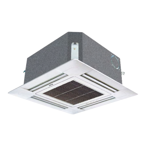
3. Round-way Smart Air Flow Cassette Type Indoor Unit 3.1 Features AB072MRERA AB092MRERA AB122MRERA AB162MRERA AB182MRERA AB242MRERA AB282MRERA AB302MRERA AB382MRERA AB482MRERA AB602MRERA ■ Unique round-way air outlet, no blind spot ■ Innovative 4 independent air flow control ■ 6 adjustable louver positions, 1296 air flow combinations ■... -
Page 44: Specification
3.2 Specification Model AB072MRERA AB092MRERA AB122MRERA Power supply V-Ph-Hz 1/220~230/50/60 1/220~230/50/60 1/220~230/50/60 Capacity kBtu/h 12.3 Capacity Cooling Power input Current 0.15 0.15 0.15 Capacity kBtu/h 10.9 13.6 Capacity Power input Heating Current 0.15 0.15 0.15 Heating capacity at low temp. - Page 45 Model AB072MRERA AB092MRERA AB122MRERA Cabinet coating Galvanized Galvanized Galvanized type Cabinet salt spray Cabinet Hour test duration Control box IP class IP40 IP40 IP40 Sheet metal thickness Drain pan material Construction Drain pan insulation Drain pump option Standard 1200mm Standard 1200mm...
- Page 46 IP40 IP40 IP40 Indoor motor Power input Power output Capacitor μF Speed (High/ 300-600 300-600 300-750 Middle/Low) Brand Haier Haier Haier Indoor fan Type Centrifugal Centrifugal Centrifugal Quantity Number of rows Tube pitch (a) x row 21*13.3 21*13.3 21*13.3 pitch (b) Fin spacing 1.45...
- Page 47 Model AB162MRERA AB182MRERA AB242MRERA Cabinet coating Galvanized Galvanized Galvanized type Cabinet salt spray Cabinet Hour test duration Control box IP class IP40 IP40 IP40 Sheet metal thickness Drain pan material Construction Drain pan insulation Drain pump option Standard 1200mm Standard 1200mm Standard 1200mm Branch outlet option Material...
- Page 48 IP40 IP40 IP40 Indoor motor Power input Power output Capacitor μF Speed (High/ 300-750 350-850 350-850 Middle/Low) Brand Haier Haier Haier Indoor fan Type Centrifugal Centrifugal Centrifugal Quantity Number of rows Tube pitch (a) x row 21*13.3 21*13.3 21*13.3 pitch (b) Fin spacing 1.45...
- Page 49 Model AB282MRERA AB302MRERA AB382MRERA Cabinet coating Galvanized Galvanized Galvanized type Cabinet salt spray Cabinet Hour test duration Control box IP class IP40 IP40 IP40 Sheet metal thickness Drain pan material Construction Drain pan insulation Drain pump option Standard 1200mm Standard 1200mm Standard 1200mm Branch outlet option Material...
- Page 50 IP class IP40 IP40 Indoor motor Power input Power output Capacitor μF Speed (High/ 350-850 400-850 Middle/Low) Brand Haier Haier Indoor fan Type Centrifugal Centrifugal Quantity Number of rows Tube pitch (a) x row 21*13.3 21*13.3 pitch (b) Fin spacing 1.45...
- Page 51 Model AB482MRERA AB602MRERA Cabinet coating Galvanized Galvanized type Cabinet salt spray Cabinet Hour test duration Control box IP class IP40 IP40 Sheet metal thickness Drain pan material Construction Drain pan insulation Drain pump option standard 1200mm standard 1200mm Branch outlet option Material Hot zinc plate Hot zinc plate...
-
Page 52: Dimension
3.3 Dimension... -
Page 53: Piping Diagram
3.4 Piping diagram... -
Page 54: Wiring Diagram
3.5 Wiring diagram... -
Page 55: Electric Characteristics
3.6 Electric characteristics Units Power supply Indoor fan motor Power input (w) Volt. Output Model Phase Voltage Cooling Heating range AB072MRERA 50/60 198~242 0.39 1.24 0.31 AB092MRERA 50/60 198~242 0.39 1.24 0.31 AB122MRERA 50/60 198~242 0.39 1.24 0.31 AB162MRERA 50/60 198~242 0.39... -
Page 56: Air Flow And Fan Speed Curve
3.7 Air flow and fan speed curve Air flow (m AB072-182MRERA AB242-282MRERA AB302-382MRERA AB482-602MRERA 1. Strong speed 2. High speed 3. Medium speed 4. Low speed 5. Quiet... -
Page 57: Sound Pressure Level
3.8 Sound pressure level 1) Testing illustrate: 2) Testing condition: a: Unit running in the normal condition b: Test in the semi-anechoic chamber c: Noise level varies from the actual factors such as room structure, etc. AB242-282MRERA AB072-182MRERA Limit of Limit of audible audible... -
Page 58: Installation
3.9 Installation 3.9.1 Safety ■ If the air conditioner is transferred to a new user, this manual shall be transferred to the user, together with the conditioner. ■ Before installation, be sure to read Safety Considerations in this manual for proper installation. ■... - Page 59 ■ This appliance can be used by children aged from 8 years and above and persons with reduced physical, sensory or mental capabilities or lack of experience and knowledge if they have been given supervision or instruction concerning use of the appliance in a safe way and understand the hazards involved. Children shall not play with the appliance.
- Page 60 3.9.2 Maintenance ATTENTION ■ Repair can only be performed by professional personnel. ■ Before touching the connection line, all power supplies should be switched off. Only after switching off the power supply can the operator clean the air conditioner as to avoid electric shock or injury. ■...
- Page 61 Installing air cleaner and air inlet grid: 1. Mounting the gauze: opposite to the ways of dismantling the gauze (as shown in Fig. 3 above). lock device 2. Mounting the air inlet grid: as shown in the right figure, nip the lock port locks on the grid as directed by arrows, put the side with the locks...
- Page 62 3.9.3 Fault checkup Please check the following when consigning repair service: Symptoms Reasons Water flow sound can be heard when starting operation, during operation or immediately after stopping operation. When it starts to work for 2-3 Water flow sound minutes, the sound may become louder, which is the flowing sound of refrigerant or the draining sound of condensed water.
- Page 63 3.9.4 Installation procedures The standard attached accessories of the units of this series refer to the packing list; prepare other accessories according to the requirements of the local installation point of our company. Indoor units should be installed in places with the environment of even circulation of cool and warm blows. The following places should be avoided.
- Page 64 2. Location Relationship Among Ceiling Hole, Unit and Hoisting Studs 765 (spacing of hanging screw) 850 (indoor unit) 890 (ceiling opening) 950 (trim panel) Hanger bracket Model AB072~182MRERA AB242~282MRERA AB302~382MRERA AB482~602MRERA Trim panel Ceiling Distance between indoor Distance between indoor unit unit and ceiling ≤...
- Page 65 4. Hoisting Stud Installation ■ To support the weight of the unit, use barb bolts in the situation with the ceiling. In the situation with the new ceiling, use inlaid bolts, embedded bolts or other parts provided on site. Before proceeding the installation, adjust the gap between the bolts and the ceiling.
- Page 66 Installation Refrigerant pipe Housing (1) Confirming the position of unit hanger Indoor unit Please confirm the installation position of the hanger Drain pipe for indoor unit is about 130mm above the ceiling. For details, please refer to the Instructions for Installation and Maintenance of indoor unit.
- Page 67 8) Installing the air-inlet grille. If the elevation level of the indoor unit and drain pipe Install the air-inlet grille with the steps opposite to that are not affected, you can adjust the height of the for removing. indoor unit through the corner pore on the trim panel. For reference Please keep the unit horizontal in the process of The method for removing angle trim panels when the...
- Page 68 Piping Materials & Heat Insulating Materials Piping Hard PVC tube VP31.5mm As to prevent condensation, heat insulating treatment should be material (inner bore) performed. The heat insulating treatment for piping should be done Heat insulating Vesicant polythene thickness: respectively. material over 7mm Hose The attached hoses can be used to adjust the eccentricity and angle of the hard PVC tube.
- Page 69 Tubing Permissible Length & Height Difference Please refer to the attached manual of outdoor units. Tubing Materials & Specifications Please refer to the attached manual of outdoor units. Model AB072~092MRERA AB122~182MRERA AB242~602MRERA Gas pipe Ø9.52 Ø12.7 Ø15.88 Tubing size (mm) Liquid pipe Ø6.35 Ø6.35...
- Page 70 Connecting 1. Connecting circular terminals The connecting method of circular terminal is shown in the Fig. Take off the screw, connect it to the terminal tier after heading it through the ring at the end of the lead and then tighten it. Connecting circular terminals...
- Page 71 3.9.5 Electrical wiring WARNING ■ Electrical construction should be made with specific mains circuit by the qualified personnel according to the installation instruction. Electric shock and fire may be caused if the capacity of power supply is not sufficient. ■ During arranging the wiring layout, specified cables should be used as the mains line, which accords with the local regulations on wiring.
- Page 72 Signal Wiring Drawing Outdoor units are of parallel connection via three lines with polarity. The master unit, central control and all indoor units are of parallel connection via two lines without polarity. There are three connecting ways between wired controller and indoor units: A.
- Page 73 The wiring for the power line of indoor unit, the wiring between indoor and outdoor units as well as the wiring between indoor units: Cross sectional Items Rated Rated current of residual area of signal Line Cross Length current of circuit breaker (A) Total section...
- Page 74 3.9.6 Test run Before Test Run ■ Before switching it on, test the supply terminal tier (L, N terminals) and grounding points with 500V megaohm meter and check if the resistance is above 1MΩ. It can't be operated if it is below 1MΩ. ■...
-
Page 75: Mini 4-Way Cassette Type Indoor Unit
4. MINI 4-way cassette type indoor unit 4.1 Features • Compact design • New panel design 620*620mm • Low sound level... -
Page 76: Specification
Type Insulation Class INDOOR IP Class IP40 IP40 IP40 MOTOR Power Input Power output Capacitor μF Speed (High/Middle/Low) Brand Haier Haier Haier INDOOR Type Centrifugal Centrifugal Centrifugal Quantity a. Number of rows b. Tube pitch(a)x row pitch(b) 21*13.3 21*13.3 21*13.3 c. - Page 77 Model AB052MCERA(M) AB072MCERA(M) AB092MCERA(M) Sheet Metal Thickness Drain Pan Material Construction Drain Pan Insulation Drain Pump Option Standard 1200mm Standard 1200mm Standard 1200mm Branch Outlet Option Material Hot zinc plate Hot zinc plate Hot zinc plate Indoor Wall Thickness Double or Single Skin Single Single Single...
- Page 78 Type Insulation Class INDOOR IP Class IP40 IP40 IP40 MOTOR Power Input Power output Capacitor μF Speed (High/Middle/Low) Brand Haier Haier Haier INDOOR Type Centrifugal Centrifugal Centrifugal Quantity a. Number of rows b. Tube pitch(a)x row pitch(b) 21*13.3 21*13.3 21*13.3 c.
- Page 79 Model AB122MCERA(M) AB162MCERA(M) AB182MCERA(M) Sheet Metal Thickness Drain Pan Material Construction Drain Pan Insulation Drain Pump Option Standard 1200mm Standard 1200mm Standard 1200mm Branch Outlet Option Material Hot zinc plate Hot zinc plate Hot zinc plate Indoor Wall Thickness Double or Single Skin Single Single Single...
-
Page 80: Dimension
4.3 Dimension Decoration board620 Indoor units570 Less than100 ⑦ Pipe connection diagram Connect drain pipe *At least 1500 ⑥ ⑤ Space needed for ④ installation Suspending *At least 1500 bolt 4-M8~M10 *Electric box *Electric box maintenance window 600×600 *At least 1500 *At least 1500 ③... -
Page 81: Piping Diagram
4.4 Piping diagram... -
Page 82: Wiring Diagram
4.5 Wiring diagram... -
Page 83: Electric Characteristics
4.6 Electric characteristics Units Power supply Indoor fan motor Power input (w) Volt. Output Model Phase Voltage Cooling Heating range AB052MCERA(M) 50/60 198~242 0.325 1.04 0.26 AB072MCERA(M) 50/60 198~242 0.325 1.04 0.26 AB092MCERA(M) 50/60 198~242 0.325 1.04 0.26 AB122MCERA(M) 50/60 198~242 0.325 1.04... -
Page 84: Air Velocity And Temperature Distribution
4.7 Air velocity and temperature distribution a. Cooling / Air velocity distribution Cooling Blowy angle: 40 Air velocity distribution 2.7m 1.5m/s 1.5m/s 1.0m/s 1.0m/s 0.5m/s 0.5m/s b. Cooling / Temperature distribution Cooling Blowy angle: 40 Temperature distribution 2.7m... - Page 85 c. Heating / Air velocity distribution Heating Blowy angle: 70 Air velocity distribution 2.7m 1.5m/s 1.5m/s 1.0m/s 1.0m/s 0.5m/s 0.5m/s d. Heating / Temperature distribution Heating Blowy angle: 70 Temperature distribution 2.7m 27℃ 27 ℃ 25 ℃ 25℃ 22 ℃ 22℃...
-
Page 86: Sound Pressure Level
Sound pressure level 1) Testing illustrate: 2) Testing condition: a: Unit running in the normal condition b: Test in the semi-anechoic chamber c: Noise level varies from the actual factors, such as room structure, etc. AB052-092MCERA(M) AB122-182MCERA(M) Limit of Limit of audible audible continuous... -
Page 87: Installation
4.9 Installation 4.9.1Parts and functions Indoor unit Wind deflector Electrical cabinet (Regulate wind direction with remote controller) Inlet grid Air cleaner (In inlet grid) - Page 88 4.9.2 Safety ■ If the air conditioner is transferred to a new user, this manual shall be transferred to the user, together with the conditioner. ■ Before installation, be sure to read Safety Considerations in this manual for proper installation. ■...
- Page 89 CAUTION ■ The air conditioner should be effectively grounded. Electric shocks may occur if the air conditioner is ungrounded or inappropriately grounded. The wire for earthing shouldn't be connected to the connections on the gas pipe, water pipe, lightning rod or telephone. ■...
- Page 90 4.9.3 Maintenance Attention ■ Repair can only be performed by professional personnel. ■ Before touching the connection line, all power supplies should be switched off. Only after switching off the power supply can the operator clean the air conditioner as to avoid electric shock or injury. ■...
- Page 91 Installing air cleaner and air inlet grid: 1. Mounting the gauze: opposite to the ways of dismantling the gauze lock device (as shown in Fig. 3 above). lock port 2. Mounting the air inlet grid: as shown in the right figure, nip the locks on the grid as directed by arrows, put the side with the lock locks device into the lock port, and then put the side with locks into the...
- Page 92 4.9.4 Fault checkup Please check the following when consigning repair service: Symptoms Reasons Water flow sound can be heard when starting operation, during operation or immediately after stopping operation. When it starts to work for 2-3 minutes, Water flow sound the sound may become louder, which is the flowing sound of refrigerant or the draining sound of condensed water.
- Page 93 4.9.5 Installation procedures The standard attached accessories of the units of this series refer to the packing list; prepare other accessories according to the requirements of the local installation point of our company. Indoor units should be installed in places with the environment of even circulation of cool and warm blows. The following places should be avoided.
- Page 94 2. Location Relationship among Ceiling Hole, Unit and Hoisting Studs Gap between studs 535mm Indoor unit 570mm The ceiling and decorated board overlapping part should be more than 25mm decorated board ceiling Note: Before suspending the indoor unit, select the installation location according to the piping and wiring in the ceiling, and determine the lead direction of the piping.
- Page 95 4. Hoisting Stud Installation ■ To support the weight of the unit, use barb bolts in the situation with the ceiling. In the situation with the new ceiling, use inlaid bolts, embedded bolts or other parts provided on site. Before installation, adjust the gap between the bolts and the ceiling.
- Page 96 Installing the decorated board on the body of indoor unit: Receiving window for remote control The lamp will not flash when wired controller is used ■ Limits when mounting the board: mount the board as shown in the figure. Incorrect direction may cause air leakage, and meanwhile the swinging and receiving displays can't be connected.
- Page 97 Attention ■ For proper drainage, the drainpipes should be connected according to the installation manual. Heat preservation should be performed as to prevent condensing. Improper connections may cause the water leakage. Requirements: ■ The drainpipe of the indoor unit should be heat-insulated. ■...
- Page 98 Lifting Drainpipe hose hose clamp The drainpipe can be lifted 360mm. When the down gradient of the drainpipe can't be ensured, after upright lifting, the drainpipe is in the down slope. heat insulating attached heat material insulating material horniness pvc pipe Confirming Drainage The drainage should be confirmed during the test run to make sure that there is leakage at the connection.
- Page 99 Connecting Procedures of Refrigerant Tubing Proceed the flare tube connecting operation to connect all the refrigerant tubes. ■ Dual wrenches must be used in the connection of indoor unit tubing. ■ Mounting torque refers to the right table Outer Diameter of Tubing Mounting Torque Increase mounting Torque (mm)
- Page 100 4.9.6 Electrical wiring WARNING ■ Electrical construction should be made with specific mains circuit by the qualified personnel according to the installation instruction. Electric shock and fire may be caused if the capacity of power supply is not sufficient. ■ During arranging the wiring layout, specified cables should be used as the mains line, which accords with the local regulations on wiring.
- Page 101 Signal Wiring Drawing Outdoor units are of parallel connection via three lines with polarity. The master unit, central control and all indoor units are of parallel connection via two lines without polarity. There are three connecting ways between wired controller and indoor units: A.
- Page 102 The wiring for the power line of indoor unit, the wiring between indoor and outdoor units as well as the wiring between indoor units: Cross sectional Items Rated Rated current of residual area of signal Line Cross Length current of circuit breaker (A) Total section...
-
Page 103: Way Cassette Type Indoor Unit
5. 2-Way Cassette Type Indoor Unit 5.1 Features AB072MBERA AB092MBERA AB122MBERA AB162MBERA AB182MBERA Compact design: only 220mm height 15mm 220mm Ceiling Built in high head drain pump 220mm Ceiling antifouling design Unique antifouling design Two way air flow Quite operation 5 models ranging from 2.2kW to 5.6kW... -
Page 104: Specification
Power input Power output Capacitor μF 3μF /450v 3μF /450v 3μF /450v Speed (High/Middle/Low) 670/530/440 670/530/440 670/530/440 Brand Haier Haier Haier Indoor fan Type Centrifugal Centrifugal Centrifugal Quantity a. Number of rows b. Tube pitch (a)×row pitch (b) 22x19.04 22×19.04 22×19.04... - Page 105 MODEL AB072MBERA AB092MBERA AB122MBERA Cabinet coating type Cabinet salt spray test Cabinet Hour duration Control box IP class IP20 IP20 IP20 Sheet metal thickness Drain pan material Construction Drain pan insulation Drain pump option Standard 700mm Standard 700mm Standard 700mm Branch outlet option Material Indoor wall...
- Page 106 IP20 IP20 Power input Power output Capacitor μF 3μF /450v 3μF /450v Speed (High/Middle/Low) 670/530/440 670/530/440 Brand Haier Haier Indoor fan Type Centrifugal Centrifugal Quantity a. Number of rows b. Tube pitch (a)×row pitch (b) 21×13.2 21×13.2 c. Fin spacing Indoor coil d.
- Page 107 MODEL AB162MBERA AB182MBERA Cabinet coating type Cabinet salt spray test Cabinet Hour duration Control box IP class IP20 IP20 Sheet metal thickness Drain pan material Construction Drain pan insulation Drain pump option Standard 700mm Standard 700mm Branch outlet option Material Indoor wall Thickness Double or single skin...
-
Page 108: Dimension
5.3 Dimension Ceiling 1015 Code Name Hanging bolt distance 885 Hanging bolt Pothook Fresh air entrance Exhaust outlet : 4 Control box Liquid pipe connect hole Gas pipe connect hole Drain pipe connect hole Panel center Natural drain Power line entrance 297~325 Drain pipe max. -
Page 109: Piping Diagram
5.4 Piping diagram Liquid pipe Gas pipe Filter Filter Indoor heat exchanger... -
Page 110: Wiring Diagram
5.5 Wiring diagram... -
Page 112: Electric Characteristics
5.6 Electric characteristics Unit Power supply Indoor fan motor Power input (W) Volt. Output Model Phase Voltage Cooling Heating range AB072MBERA 50/60 198~242 AB092MBERA 50/60 198~242 AB122MBERA 50/60 198~242 AB162MBERA 50/60 198~242 AB182MBERA 50/60 198~242 Symbols: MCA: Min. circuit amps (A) MFA: Max. -
Page 113: Air Velocity And Temperature Distribution
5.7 Air velocity and temperature distribution a. Cooling / Air velocity distribution Cooling Blowy angle: 40 Air Velocity distribution 2.7m 1.5m/s 1.5m/s 1.0m/s 1.0m/s 0.5m/s 0.5m/s b. Cooling / Temperature distribution Cooling Blowy angle: 40 Temperature distribution 2.7m... - Page 114 c. Heating / Air velocity distribution Heating Blowy angle: 70 Air velocity distribution 2.7m 1.5m/s 1.5m/s 1.0m/s 1.0m/s 0.5m/s 0.5m/s d. Heating / Temperature distribution Heating Blowy angle: 70 Temperature distribution 2.7m...
-
Page 115: Sound Pressure Level
5.8 Sound pressure level 1) Testing illustrate: 2) Testing condition: a: Unit running in the normal condition b: Test in the semi-anechoic chamber c: Noise level varies from the actual factors such as room structure, etc. AB07/09/122MBERA AB16/182MBERA 1000 2000 4000 8000 1000... -
Page 116: Installation
5.9 Installation 5.9.1 Installation procedures Before installation Make correct operation according to the manual when installation. Please confirm the below information: ■ If operation plan has been discussed ■ Model, power supply specs ■ Pipe, wire, and the other parts ■... - Page 117 Suspension installation Suspend the bolt with 4 M10 or W3/8. Fasten the bolt to make every bolt bear the load of 50kg. The suspension bolt should be about 95mm extending outward of ceiling. When the ceiling exists already 1. Open a hole on the ceiling, and set the dimension appropriate for the installation. 2.
- Page 118 Model AB072-182MBERA 1015 Model AB072-182MBERA Refrigerant pipe Please refer to accompanied manual to know refrigerant pipe plumbing. Gas side and liquid side should take measure of heat insulation. Inspect if gas leaks, joints heat insulation materials have to be used to connect refrigerant piping extender mouth, then, use strap to tie two parts.
- Page 119 Drainage pipe ■ Install attached flexible hose to adjust when installing panel. Bending or dragging intentionally will lead to leakage. ■ Insert attached drainage flexible hose into fine mouth end of drainage, and then fix it with pipe clamp. ■ Bind VP-25 joint (purchase in local place) to drainage flexible hose (Rigid PVC terminal) before suspending, then, bind VP-25 to this joint.
- Page 120 VP25 joint (purchase in local place) ■ Do not lay drain pipe at the place that can cause peculiar smell gas. ■ Do not put drain pipe directly into sewer that can cause harmful gas. In case of gravity drainage ■...
- Page 121 Installation of pane Bolt used should be close to panel Air supply outlet is easy to be damaged, please pay attention to it when working. 1. Use drawing block to confirm the height of unit and size of ceiling. Remove it before installing panel, as well as air return panel.
- Page 122 Connecting Procedures of Refrigerant Tubing Proceed the flare tube connecting operation to connect all the refrigerant tubes. ■ Dual wrenches must be used in the Outer diameter Mounting Increase mounting connection of indoor unit tubing. of tubing (mm) torque (N.m) torque (N.m) ■...
- Page 123 ATTENTION ■ Only copper wire can be used. Breaker for electric leakage should be provided, or electric shock may occur. ■ The wiring of the mains line is of Y type. The power plug L should be connected to the live wire and plug N connected to null wire while should be connected to the ground wire.
- Page 124 Signal Wiring Drawing Outdoor units are of parallel connection via three lines with polarity. The master unit, central control and all indoor units are of parallel connection via two lines without polarity. There are three connecting ways between wired controller and indoor units: A.
- Page 125 The combination of multiple indoor units can be controlled by wired controller or remote controller. ※ Switching mode of Wired control master unit/ Wired control slave unit/ remote control types can be used for switching over ※ Setting mode Wired control master unit Wired control slave unit Remote control Socket/dip switch...
- Page 126 5.9.3 Test run Before Test Run ■ Before switching it on, test the supply terminal tier (L, N terminals) and grounding points with 500V megaohm meter and check if the resistance is above 1MΩ. It can't be operated if it is below 1MΩ. ■...
-
Page 127: One Way Cassette Type Indoor Unit
6. One Way Cassette Type Indoor Unit 6.1 Features ■ DC fan motor, higher efficiency ■ Only 185mm thickness, allowing more flexible design ■ Low sound level, high comfort ■ Built-in high lift drain pump. ■ No need of maintenance port, convenient and artistic... -
Page 128: Specification
Specification MODEL AB052MAERA AB072MAERA Power supply Ph-V-Hz 1/220-230/50/60 1/220-230/50/60 Capacity kBtu/h Capacity Cooling Power input Current Capacity kBtu/h Capacity Heating Power input Current Heating capacity at low temp. Operating current Brand Broad Ocean Broad Ocean Model ZWK465B500015 ZWK465B500015 Type Insulation class Indoor motor IP class IP20... - Page 129 MODEL AB052MAERA AB072MAERA Cabinet coating type Galvanized Galvanized Cabinet salt spray test Cabinet Hour duration Control box IP class IP40 IP40 Sheet metal thickness Drain pan material Construction Drain pan insulation UL-V0 UL-V0 Drain pump option Standard 1200mm Standard 1200mm Branch outlet option Material Indoor wall...
- Page 130 MODEL AB092MAERA AB122MAERA Power supply Ph-V-Hz 1/220-230/50/60 1/220-230/50/60 Capacity kBtu/h 12.3 Capacity Cooling Power input Current 0.11 Capacity kBtu/h 10.9 13.6 Capacity Heating Power input Current 0.11 Heating capacity at low temp. Operating current 0.11 Brand Broad Ocean Broad Ocean Model ZWK465B500015 ZWK465B500015...
- Page 131 MODEL AB092MAERA AB122MAERA Cabinet coating type Galvanized Galvanized Cabinet salt spray test Cabinet Hour duration Control box IP class IP40 IP40 Sheet metal thickness Drain pan material Construction Drain pan insulation UL-V0 UL-V0 Drain pump option Standard 1200mm Standard 1200mm Branch outlet option Material Indoor wall...
-
Page 132: Dimension
Dimension Installation space At least 100 Air return,electrical box At least 100 At least 100 Air outlet ⑤ ⑥ At least 1500 There shall be no ※when inlet grill is closed, obstacles in front of the the least reserved space is air outlet, such as 300mm droplight, screen, etc... -
Page 133: Piping Diagram
Piping diagram Indoor heat exchanger Gas pipe ( Flared joint ) Liquid pipe ( Flared joint ) Filter Filter... -
Page 134: Wiring Diagram
Wiring diagram... -
Page 135: Electric Characteristics
Electric characteristics Units Power supply Indoor fan motor Power input (w) Volt. Output Model Phase Voltage Cooling Heating range AB052MAERA 50/60 198~242 0.088 0.28 0.07 AB072MAERA 50/60 198~242 0.088 0.28 0.07 AB092MAERA 50/60 198~242 0.088 0.28 0.07 AB122MAERA 50/60 198~242 0.088 0.28 0.07... -
Page 136: Air Velocity And Temperature Distribution
Air velocity and temperature distribution a.Cooling / Air velocity distribution Cooling Blowy angle:40 Air velocity distribution 2.7m 1.5m/s 1.0m/s 0.5m/s b.Cooling / Temperature distribution Cooling Blowy angle:40 Temperature distribution 2.7m... - Page 137 c.Heating / Air velocity distribution Heating Blowy angle:70 Air velocity distribution 2.7m 1.5m/s 1.0m/s 0.5m/s d.Heating / Temperature distribution Heating Blowy angle:70 Temperature distribution 2.7m...
-
Page 138: Sound Pressure Level
Sound pressure level 1) Testing illustrate: 2) Testing condition: a: Unit running in the normal condition b: Test in the semi-anechoic chamber c: Noise level varies from the actual factors, such as room structure, etc. AB052-092MAERA AB122MAERA NC-60 NC-60 NC-50 NC-50 NC-40 NC-40... -
Page 139: Installation
Installation 6.9.1 Parts and functions Indoor unit Drain pipe Liquid inlet pipe Injection nozzle Gas return pipe Air-out guide plate (using the wind direction adjusting key of remote controller to adjust air- out direction) Receive window and function indicator of remote controller (used for remote control models) Electrical box assy(in... - Page 140 ■ Haier is not responsible for any personnel damage or equipment damage caused by improper installation, improper commissioning, unnecessary maintenance and the wrong operation which violates the instructions in this manual or industry specifications and standards.
- Page 141 CAUTION ■ The drainpipe should be properly mounted according to this manual as to ensure the smooth drainage. In addition, heat preservation should be taken to avoid condensation. Improper drainpipe mounting might cause water leakage, which will get the articles at home wet. ■...
- Page 142 Notices during Operation ■ Do not put flammable spray close to the air conditioner. Don't inject flammable spray towards the air conditioner, which may cause fire. ■ Close the window to avoid outdoor air getting in. Curtains or window shutters can beput down to avoid the sunshine.
- Page 143 6.9.3 Maintenance Attention ■ Repair can only be performed by professional personnel. ■ Before touching the connection line, all power supplies should be switched off. Only after switching off the power supply can the operator clean the air conditioner as to avoid electric shock or injury. ■...
- Page 144 Install the air cleaner & Inlet guide plate 1.Install the air cleaner: The method is contrary to the method of removing the dust screen. 2.Install the Inlet guide plate: As shown below, the rack on the return air guide plate is inserted into the gear box. The hole of gear wheel box Rack Cleaning the air outlet port and the shell...
- Page 145 6.9.4 Fault checkup Please check the following when consigning repair service: Symptoms Reasons Water flow sound can be heard when starting operation, during operation or immediately after stopping operation. When it starts to Water flow sound work for 2-3 minutes, the sound may become louder, which is the flowing sound of refrigerant or the draining sound of condensed water.
- Page 146 6.9.5 Installation procedures Before installation • Do not throw away the included parts before installation. • Determine the handling route from the unit to the installation location • Before moving the unit to the installation position, do not remove the packaging, had to remove the packaging, with a soft material or protective plate with a rope to lift the unit, so as not to damage the unit or wipe scratches.
- Page 147 2. Location Relationship among Ceiling Hole, Unit and Hoisting Studs Ceiling opening center Four hanging screw center 874 (indoor unit) 913 (spacing of hanging screw) 1025 (ceiling opening) (trim panel) 1050 Note: Before suspending the indoor unit, select the installation location according to the piping and wiring in the ceiling, and determine the lead direction of the piping.
- Page 148 Ceiling Suspending Situation with New Ceiling (1) Install the indoor unit temporarily: attach the hoisting foot to hoisting stud. Make sure that nuts and washers should be used at two ends of the foot to secure the foot. (2) For the size of the ceiling hole, please refer to the schematic drawing at the previous page. <After finishing the installation of the ceiling>...
- Page 149 ■ Install the two claws into the snap and secure with the screws. (Screw hole position as shown, hidden parts have been hidden). snap claws Decorative panels of the line ■ Connect the connector on the right side of the trim panel to the stepped motor wire (10-pin) ■...
- Page 150 Drainpipes Requirements: ■ The drainpipe of the indoor unit should be heat-insulated. ■ Heat insulation should be treated for the connection with the indoor unit. Improper heat insulation may cause condensing. ■ The drainpipe with the down gradient of over 1/100 can't be in the S shape, or abnormal sound can be caused. ■...
- Page 151 Heat Insulating Treatment: hose hose clamp ■ Wrap the connection between the clamp and the root segment of the indoor unit without any gap with heat insulating materials as shown in the drawing heat insulating attached heat material insulating material horniness pvc pipe Lifting Drainpipe The drainpipe can be lifted 450mm.
- Page 152 Refrigerant Filling Amount Add the refrigerant according to the installation instruction of outdoor unit. The addition of R410A refrigerant must be performed with a measure gage to ensure the specified amount while compressor failure can be caused by filling too much or little refrigerant. Connecting Procedures of Refrigerant Tubing Proceed the flare tube connecting operation to connect all the refrigerant tubes.
- Page 153 6.9.6 Electrical wiring WARNING ■ Electrical construction should be made with specific mains circuit by the qualified personnel according to the installation instruction. Electric shock and fire may be caused if the capacity of power supply is not sufficient. ■ During arranging the wiring layout, specified cables should be used as the mains line, which accords with the local regulations on wiring.
- Page 154 4.Electronic control box connection operation method First, remove the screw of the fixed electric control box, pull out the electric control box, and then remove the electric control box cover fixing screw, take off the electric control box cover (both hands press and hold the button at the same time). Signal line through the machine through the hole, and then through the electronic control box hole into the box body, pay attention to the separation of strength.
- Page 155 Signal Wiring Drawing (This machine) (AC machine) (AC machine) (DC machine) Outdoor units are of parallel connection via three lines with polarity. The main unit, central control and all indoor units are of parallel connection via two lines without polarity. There are three connecting ways between line control and indoor units: A.
- Page 156 The wiring for the power line of indoor unit, the wiring between indoor and outdoor units as well as the wiring between indoor units: Cross Sectional Items Rated current of residual Rated Area of Signal Line Cross Circuit Breaker(A) Length Current of Total Section...
-
Page 157: Convertible Type Indoor Unit
7. Convertible Type Indoor Unit 7.1 Features AC092MCERA AC282MFERA AC122MCERA AC302MFERA AC162MCERA AC382MFERA AC182MCERA AC482MFERA AC242MCERA Ultra thin unit, only thick 199mm The convertible unit adopts a double drain pan design. The unit body of AV09-24 is only thick 199mm. Slim, elegant and beautiful, supply more decoration to indoor. -
Page 158: Specification
Power input Power output Capacitor μF 2μF /450v 2μF /450v 2μF /450v Speed (High/Middle/Low) 1110/1005/745 1110/1005/745 1110/1005/745 Brand Haier Haier Haier Indoor fan Type Centrifugal Centrifugal Centrifugal Quantity a. Number of rows b. Tube pitch (a)×row pitch (b) 21×13.3 25×21.65 25×21.65... - Page 159 MODEL AC092MCERA AC122MCERA AC162MCERA Cabinet coating type Plastic Plastic Plastic Cabinet salt spray test Cabinet Hour duration Control box IP class IP20 IP20 IP20 Sheet metal thickness Drain pan material Construction Drain pan insulation Drain pump option Branch outlet option Material Plastic Plastic...
- Page 160 Power input Power output Capacitor μF 2μF /450v 2μF /450v 5μF /450v Speed (High/Middle/Low) 1110/1005/745 1110/1005/745 1120/1040/900/820 Brand Haier Haier Haier Indoor fan Type Centrifugal Centrifugal Centrifugal Quantity a. Number of rows b. Tube pitch (a)×row pitch (b) 25×21.65 25×21.65 21×13.3...
- Page 161 MODEL AC182MCERA AC242MCERA AC282MFERA Cabinet coating type Plastic Plastic Plastic Cabinet salt spray test Cabinet Hour duration Control box IP class IP20 IP20 IP20 Sheet metal thickness Drain pan material Construction Drain pan insulation Drain pump option Branch outlet option Material Plastic Plastic...
- Page 162 Power input Power output Capacitor μF 5μF /450v 5μF /450v 5μF /450v Speed (High/Middle/Low) 1120/1040/900/820 1395/1245/1090/980 1395/1245/1090/980 Brand Haier Haier Haier Indoor fan Type Centrifugal Centrifugal Centrifugal Quantity a. Number of rows b. Tube pitch (a)×row pitch (b) 21×13.3 21×13.3...
- Page 163 MODEL AC302MFERA AC382MFERA AC482MFERA Cabinet coating type Plastic Plastic Plastic Cabinet salt spray test Cabinet Hour duration Control box IP class IP20 IP20 IP20 Sheet metal thickness Drain pan material Construction Drain pan insulation Drain pump option Branch outlet option Material Plastic Plastic...
-
Page 164: Dimension
7.3 Dimension AC092-242MCERA... - Page 165 AC282-482MFERA...
-
Page 166: Piping Diagram
7.4 Piping diagram Liquid pipe Gas pipe Filter Filter Indoor heat exchanger... -
Page 167: Wiring Diagram
7.5 Wiring diagram 3 2 1 3 2 1... -
Page 168: Electric Characteristics
7.6 Electric characteristics Units Power supply Indoor fan motor Power input (W) Volt. Output Model Phase Voltage Cooling Heating range AC092MCERA 50/60 198~242 0.64 2.04 0.51 AC122MCERA 50/60 198~242 0.64 2.04 0.51 AC162MCERA 50/60 198~242 0.64 2.04 0.51 AC182MCERA 50/60 198~242 0.64 2.04... -
Page 169: Air Velocity And Temperature Distribution
7.7 Air velocity and temperature distribution A) On the floor a. Cooling / Air velocity distribution Coolin g Blowy angle: 25 Air velocity distribution 2.4m 0.5m/s 1.0m/s 1.5m/s 5.5m b. Cooling / Temperature distribution Coolin g Blowy angle: 25 Temperature distribution 2.4m 27 ℃... - Page 170 c. Heating / Air velocity distribution Heating Blowy angle: 5 Air velocity distribution 2.4m 0.5m/s 1.0m/s 1.5m/s 5.5m d. Heating / Temperature distribution Heating Blowy angle: 5 Temperature distribution 2.4m ℃ ℃ ℃ 5.5m...
- Page 171 B) Ceiling a. Cooling / Air velocity distribution Cooling Blowy angle: 25 Air velocity distribution 2.4m 1.5m/s 1.0m/s 0.5m/s 5.5m b. Cooling / Temperature distribution Cooling Blowy angle: 25 Temperature distribution 2.4m 22℃ 25℃ 27℃ 5.5m...
- Page 172 c. Heating / Air velocity distribution Heating Blowy angle: 65 Air velocity distribution 2.4m 1.5m/s 1.0m/s 0.5m/s 5.5 m d. Heating / Temperature distribution Heating Blowy angle: 65 Temperature distribution 2.4m 27℃ 25℃ 22℃ 5.5 m...
-
Page 173: Sound Pressure Level
7.8 Sound pressure level (1) Testing illustrate: (2) Testing condition: a. Unit running in the nominal condition b. Test in the semi-anechoic chamber c. Noise level varies from the actual factors such as room structure, etc. (3) Octave band level: AC09~242MCERA AC28~302MFERA Limit of... -
Page 174: Installation
7.9 Installation 7.9.1 Installation procedures Please contact Haier local center if any problem or request. Standard installation tools are recommended according to installation requirements. For information about standard model series accessories, see packing list; other necessary parts to be installed shall be prepared by users as required by installation service network stations. - Page 175 3. Floor Type Installation ① Fix four rubber feet to the bottom of the unit with *4×16 bolts and Φ12 spacers (applicable to floor type units only). ② According to figure on the right, choose a certain direction to lead out drain pipe;...
- Page 176 CAUTION: Drain pipe leading-out direction shown with figure below. Attention to distance from the unit to the obstacles (as shown with figure). 4. Ceiling Installation Model AC092-242MCERA Over 30cm Over 30cm Over 2cm AC282-482MFERA Over 80cm Over 150cm Over 10cm Ceiling Installation ①...
- Page 177 Model AC282-482MFERA ② Installing Hang Bolt Use M10 hanger bolt (prepared on the site) featuring 60mm hole depth, clearance fixed according to size proposed in the air conditioner external view; install according to different building structure specifications to guard against safety faults;...
- Page 178 ④ Air Conditioner Installation Diagram Insert hexagon bolt into slot. Screw tight hexagon bolt to fix air Hanger bolt is 40mm below ceiling. conditioner. CAUTION: Drain pipe shall be positioned high inside and low outside. Leveling is forbidden after air conditioner is According to requirements on the site, drain installed;...
- Page 179 ATTENTION ■ For normal drainage, the water drainage piping should be connected according to the installation manual. Heat insulation should be performed to avoid condensation. Improper pipe connection may cause water going into the machine. Requirements: ■ Heat insulating treatment should be made for the water drainpipes of the indoor units. ■...
- Page 180 Pipe Length & Height Difference Please refer to the attached manual of outdoor units. AC242MCERA Model AC092MCERA AC122-182MCERA AC28~482MFERA Gas pipe Φ9.52 Φ12.7 Φ15.88 Pipe Size (mm) Liquid pipe Φ6.35 Φ6.35 Φ9.52 Pipe Phosphor deoxy bronze seamless pipe (TP2) for air conditioner Material Refrigerant Recharge Amount Add the refrigerant according to the installation instruction of outdoor unit.
- Page 181 7.9.2 Electrical wiring WARNING ■ Electrical construction should be made with specific mains circuit by the qualified personnel according to the installation instruction. Electric shock and fire may be caused if the capacity of power supply is not sufficient. ■ During arranging the wiring layout, specified cables should be used as the mains line, which accords with the local regulations on wiring.
- Page 182 Signal Wiring Drawing Outdoor units are of parallel connection via three lines with polarity. The master unit, central control and all indoor units are of parallel connection via two lines without polarity. There are three connecting ways between wired controller and indoor units: A.
- Page 183 The combination of multiple indoor units can be controlled by wired controller or remote controller. ※ Switching mode of Wired control master unit/ Wired control slave unit/ remote control types can be used for switching over ※ Setting mode Wired control master unit Wired control slave unit Remote control Socket/dip...
- Page 184 7.9.3 Test run Before Test Run ■ Before switching it on, test the supply terminal tier (L, N terminals) and grounding points with 500V megaohm meter and check if the resistance is above 1MΩ. It can't be operated if it is below 1MΩ. ■...
-
Page 185: Slim Duct Type Indoor Unit
8. Slim Duct Type Indoor Unit 8.1 Features AD052MSERA AD072MSERA AD092MSERA AD122MSERA AD162MSERA AD182MSERA AD242MSERA 1.185mm height ultra thin design and 420mm depth 2. Built in drain pump 3. Ultra low noise: realize 21dB (A) operation noise 4. Rear air return 5. -
Page 186: Specification
Power Input Power output 15.5/14 25/23 Capacitor μF 1.5/1.2μF 1.5/3.0μF Speed (High/Middle/Low) 670/580/500 950/765/600 Brand Haier Haier Indoor fan Type centrifugal centrifugal Quantity a. Number of rows b. Tube pitch (a)×row pitch (b) 21*13.3 21*13.3 c. Fin spacing Indoor coil d. - Page 187 MODEL AD052MSERA AD072MSERA Cabinet coating type Galvanized Galvanized Cabinet salt spray test Cabinet Hour duration Control box IP class IP20 IP20 Sheet metal thickness Drain pan material Construction Drain pan insulation Drain pump option Standard 600mm Standard 600mm Branch outlet option Material Hot zinc plate Hot zinc plate...
- Page 188 Power Input Power output 25/23 25/23 Capacitor μF 1.5/3.0μF 1.5/3.0μF Speed (High/Middle/Low) 950/765/600 950/765/600 Brand Haier Haier Indoor fan Type centrifugal Centrifugal Quantity a. Number of rows b. Tube pitch (a)×row pitch (b) 21*13.3 21*13.3 c. Fin spacing Indoor coil d.
- Page 189 MODEL AD092MSERA AD122MSERA Cabinet coating type Galvanized Galvanized Cabinet salt spray test Cabinet Hour duration Control box IP class IP20 IP20 Sheet metal thickness Drain pan material Construction Drain pan insulation Drain pump option Standard 600mm Standard 600mm Branch outlet option Material Hot zinc plate Hot zinc plate...
- Page 190 IP20 IP20 Power input Power output Capacitor μF 3.5μF 3.5μF 4.0μF Speed (High/Middle/Low) 1220/1060/950 1030/880/780 1210/1065/955 Brand Haier Haier Haier Indoor fan Type Centrifugal Centrifugal Centrifugal Quantity a. Number of rows b. Tube pitch (a)×row pitch (b) 21*13.3 21*13.3 21*13.3 c.
- Page 191 MODEL AD162MSERA AD182MSERA AD242MSERA Cabinet coating type Galvanized Galvanized Galvanized Cabinet salt spray test Cabinet Hour duration Control box IP class IP20 IP20 IP20 Sheet metal thickness Drain pan material Construction Drain pan insulation Drain pump option Standard 600mm Standard 600mm Standard 600mm Branch outlet option Material...
-
Page 192: Dimension
8.3 Dimension AD052-162MSERA Above 400 When air returns from rear Above 600 reserved space Above 100 Ceiling ⑤ 6×P100=600( evenly distributed) Less than 200 Suspending bolt4-M10 ① ③ ⑥ ④ ② ⑦ 4-M10 Suspending bolt 2×P260=520 (evenly distributed) 8-M10 Nut 8-M10 Gasket Zoom in section B When air returns from the bottom... - Page 193 AD182-242MSERA Above 400 When air returns Above 600 1170 from rear Reserved space Above 100 Ceiling 8×P115=920 (evenly distributed) ⑤ 1213 Less than 200 Suspending bolt4-M10 ① ③ ⑥ 4542 ② ⑦ 4-M10suspending bolt ④ 8-M10nut 8-M10gasket 1080 Zoom in 1090 section B 1100...
-
Page 194: Piping Diagram
8.4 Piping diagram Liquid pipe Gas pipe Filter Filter Indoor heat exchanger... -
Page 195: Wiring Diagram
8.5 Wiring diagram AD*MSERA PCB code: 0151800161 Gas pipe sensor TC1 Liquid pipe sensor TC2... - Page 196 AD*MSERA PCB code:0151800161C Float Switc h E EV L eft /Right U p/Down P M V Room Car d C N 35 C N 1 1 C N 1 0 C N 15 ACFA N Dehumidification CN1 3 CN1 6 sensor C N 1 1-1 LED 4...
-
Page 197: Electric Characteristics
8.6 Electric characteristics Units Power supply Indoor fan motor Power input (w) Model Phase FQY Voltage Volt range Output (W) Cooling Heating AD052MSERA 50/60 198-242 0.24 0.76 0.19 AD072MSERA 50/60 198-242 0.24 0.76 0.19 AD092MSERA 50/60 198-242 0.24 0.76 0.19 AD122MSERA 50/60 198-242... -
Page 198: Air Flow And Static Pressure Curves
8.7 Air flow and static pressure curves AD052MSERA air flow and static pressure curves Static pressure (Pa) AD07-092MSERA air flow and static pressure curves Static pressure (Pa) - Page 199 AD122MSERA air flow and static pressure curves Static pressure (Pa) AD162MSERA air flow and static pressure curves Static pressure (Pa) Static pressure (Pa)
- Page 200 AD182MSERA air flow and static pressure curves 1200 1000 Static pressure (Pa) AD242MSERA air flow and static pressure curves 1400 1200 1000 Static pressure (Pa)
-
Page 201: Sound Pressure Level
8.8 Sound pressure level Slim duct type running noise (1) Testing illustrate: The auxiliary air duct The auxiliary air duct Unit Outlet side Sound level meter Testing position just below the central of the unit Note: The length of the auxiliary air duct is 2m (2) Testing condition: a. - Page 202 AD122MSERA AD162MSERA Limit of Limit of audible audible continuous continuous noise noise 125 250 500 1000 2000 4000 8000 1000 2000 4000 8000 Octave band center frequency (HZ) Octave band center frequency (HZ) AD182MSERA AD242MSERA Limit of Limit of audible audible continuous continuous...
-
Page 203: Installation
8.9 Installation 8.9.1 Installation Procedures If you have any problem on product, contact the local Haier distribution center. Please use the standard tools according to the installation requirements. The standard attached accessories of the units of this series refer to the packing list; prepare other accessories according to the requirements of the local installation point of our company. - Page 204 AD052MSERA AD072MSERA AD092MSERA AD122MSERA AD162MSERA AD182MSERA AD242MSERA Air in Installation modes of Indoor unit This series of air conditioners can be arranged in two air return modes: 1. Backward air return (factory default); 2. Downward air return (can be adjusted on site. See the following figures.) Note: The downward air return mode would cause much more noise.
- Page 205 Installation of air-inlet grille The angle of air-inlet grille should be parallel with that of air inlet direction, otherwise it will cause more noise. As shown in the figure on the right. Installation of Duct Pipe of Indoor Units: 1. Installation of the air blowing pipe: Air return shutter Air return pipe Indoor unit With a square blast pipe, the bore shouldn't be less than...
- Page 206 Installation of drain hose Connection of indoor drain hose 1. Please use accessory drain hose to connect indoor unit's water outlet and PVC pipe and use snap rings to tighten them, as shown in the following figure: 2. Please use rigid PVC adhesive for connection of other pipes and ensure there is no leakage. 3.
- Page 207 Pipe Length & Height Difference AD072- AD122- AD242 Please refer to the attached manual of outdoor units. Model 092MSERA 182MSERA MSERA Tubing Materials & Specifications Tubing Gas pipe Ø9.52 Ø12.7 Ø15.88 Size Special tools for R410A should be used for cutting Liquid pipe Ø6.35 Ø6.35...
- Page 208 8.9.2 Electrical Wiring WARNING ■ Electrical construction should be made with specific mains circuit by the qualified personnel according to the installation instruction. Electric shock and fire may be caused if the capacity of power supply is not sufficient. ■ During arranging the wiring layout, specified cables should be used as the mains line, which accords with the local regulations on wiring.
- Page 209 Signal Wiring Drawing Outdoor 1 Outdoor 2 Outdoor 3 Control wire for wired controller with polarity Communication wire with polarity Indoor 1 Indoor 2 Indoor 3 Indoor 4 Indoor 5 Wired controller Indoor 6 Indoor 7 Indoor 8 Indoor 9 Indoor 10 Wired Wired...
- Page 210 The combination of multiple indoor units can be controlled by wired controller or remote controller. ※ Switching mode of Wired control master unit/ Wired control slave unit/ remote control types can be used for switching over ※ Setting mode Wired control master unit Wired control slave unit Remote control Socket/dip...
- Page 211 8.9.3 Test run Before Test Run Before switching it on, test the supply terminal tier (L, N terminals) and grounding points with 500V megaohm meter and check if the resistance is above 1MΩ. It can't be operated if it is below 1MΩ. Connect it to the power supply of outdoor units to energize the heating belt of the compressor.
-
Page 212: Dc Slim Duct Type Indoor Unit
9. DC Slim Duct Type Indoor Unit 9.1 Features AD052MSERA(D) AD072MSERA(D) AD092MSERA(D) AD122MSERA(D) AD162MSERA(D) AD182MSERA(D) AD242MSERA(D) 1.185mm height ultra thin design and 420mm depth 2. Built in drain pump 3. Ultra low noise: realize 21dB (A) operation noise 4. Rear air return 5. -
Page 213: Specification
Indoor motor IP class IP40 IP40 Power Input Power output Capacitor μF Speed (High/Middle/Low) 1250 1250 Brand Haier Haier Indoor fan Type centrifugal centrifugal Quantity a. Number of rows b. Tube pitch (a)×row pitch (b) 21*13.3 21*13.3 c. Fin spacing Indoor coil d. - Page 214 MODEL AD052MSERA(D) AD072MSERA(D) Cabinet coating type Galvanized Galvanized Cabinet salt spray test Cabinet Hour duration Control box IP class IP20 IP20 Sheet metal thickness Drain pan material Construction Drain pan insulation Drain pump option Standard 600mm Standard 600mm Branch outlet option Material Hot zinc plate Hot zinc plate...
- Page 215 Indoor motor IP class IP40 IP40 Power Input Power output Capacitor μF Speed (High/Middle/Low) 1250 1250 Brand Haier Haier Indoor fan Type centrifugal Centrifugal Quantity a. Number of rows b. Tube pitch (a)×row pitch (b) 21*13.3 21*13.3 c. Fin spacing Indoor coil d.
- Page 216 MODEL AD092MSERA(D) AD122MSERA(D) Cabinet coating type Galvanized Galvanized Cabinet salt spray test Cabinet Hour duration Control box IP class IP20 IP20 Sheet metal thickness Drain pan material Construction Drain pan insulation Drain pump option Standard 600mm Standard 600mm Branch outlet option Material Hot zinc plate Hot zinc plate...
- Page 217 IP class IP40 IP40 IP40 Power Input Power output Capacitor μF Speed (High/Middle/Low) 1250 1150 1150 Brand Haier Haier Haier Indoor fan Type Centrifugal Centrifugal Centrifugal Quantity a. Number of rows b. Tube pitch (a)×row pitch (b) 21*13.3 21*13.3 21*13.3 c.
- Page 218 MODEL AD162MSERA(D) AD182MSERA(D) AD242MSERA(D) Cabinet coating type Galvanized Galvanized Galvanized Cabinet salt spray test Cabinet Hour duration Control box IP class IP20 IP20 IP20 Sheet metal thickness Drain pan material Construction Drain pan insulation Drain pump option Standard 600mm Standard 600mm Standard 600mm Branch outlet option Material...
-
Page 219: Dimension
9.3 Dimension AD052-162MSERA(D) Above 400 When air returns from rear Above 600 reserved space Above 100 Ceiling ⑤ 6×P100=600( evenly distributed) Less than 200 Suspending bolt4-M10 ① ③ ⑥ ④ ② ⑦ 4-M10 Suspending bolt 2×P260=520 (evenly distributed) 8-M10 Nut 8-M10 Gasket Zoom in section B When air returns from the bottom... - Page 220 AD182-242MSERA(D) Above 400 When air returns Above 600 1170 from rear Reserved space Above 100 Ceiling 8×P115=920 (evenly distributed) ⑤ 1213 Less than 200 Suspending bolt4-M10 ① ③ ⑥ 4542 ② ⑦ 4-M10suspending bolt ④ 8-M10nut 8-M10gasket 1080 Zoom in 1090 section B 1100...
-
Page 221: Piping Diagram
9.4 Piping diagram Liquid pipe Gas pipe Filter Filter Indoor heat exchanger... -
Page 222: Wiring Diagram
9.5 Wiring diagram... -
Page 223: Electric Characteristics
9.6 Electric characteristics Units Power supply Indoor fan motor Power input (w) Model Phase FQY Voltage Volt range Output (W) Cooling Heating AD052MSERA(D) 50/60 198-242 0.24 0.76 0.19 AD072MSERA(D) 50/60 198-242 0.24 0.76 0.19 AD092MSERA(D) 50/60 198-242 0.24 0.76 0.19 AD122MSERA(D) 50/60 198-242... -
Page 224: Air Flow And Static Pressure Curves
9.7 Air flow and static pressure curves AD052MSERA(D) air flow and static pressure curves Static pressure (Pa) AD07-092MSERA(D) air flow and static pressure curves Static pressure (Pa) - Page 225 AD122MSERA(D) air flow and static pressure curves Static pressure (Pa) AD162MSERA(D) air flow and static pressure curves Static pressure (Pa) Static pressure (Pa)
- Page 226 AD182MSERA(D) air flow and static pressure curves 1200 1000 Static pressure (Pa) AD242MSERA(D) air flow and static pressure curves 1400 1200 1000 Static pressure (Pa)
-
Page 227: Sound Pressure Level
9.8 Sound pressure level Slim duct type running noise (1) Testing illustrate: The auxiliary air duct The auxiliary air duct Unit Outlet side Sound level meter Testing position just below the central of the unit Note: The length of the auxiliary air duct is 2m (2) Testing condition: a. - Page 228 AD162MSERA(D) AD122MSERA(D) Limit of Limit of audible audible continuous continuous noise noise 1000 2000 4000 8000 125 250 500 1000 2000 4000 8000 Octave band center frequency (HZ) Octave band center frequency (HZ) AD182MSERA(D) AD242MSERA(D) Limit of Limit of audible audible continuous continuous...
-
Page 229: Installation
9.9 Installation 7.9.1 Safety • This manual should always be accessible and close to this air condition equipment. • There are two types of indications, " WARNING" and " CAUTION" The indication preventing from death or heavy injury is listed as " WARNING". - Page 230 Attention • Do not put any heating apparatus • 3-minutes protection under the indoor units. The heat may To protect the unit, compressor can be cause distortion of the units. actuated with at least 3-minutes delay after stopping. • Pay attention to the ventilation to avoid •...
- Page 231 7.9.2 Maintenance Clean the air cleaner & air inlet grid. • Don't dismantle the air cleaner if not cleaning, or faults might be caused. • When the air conditioner operates in the environment with too much dust, clean the air conditioner more times (generally once every two weeks).
- Page 232 7.9.3 Fault Checkup Please check the following when consigning repair service: Symptoms Reasons Water flow sound can be heard when starting operation, during operation or immediately after stopping operation. When it starts to • Water flow sound work for 2-3 minutes, the sound may become louder, which is the flowing sound of refrigerant or the draining sound of condensed water.
- Page 233 AD052MSERA(D) AD072MSERA(D) AD092MSERA (D) AD122MSERA(D) AD162MSERA(D) AD182MSERA (D) AD242MSERA(D) Air in Installation modes of Indoor unit This series of air conditioners can be arranged in two air return modes: 1. backward air return (factory default); 2. downward air return (can be adjusted on site. See the following figures.) Note: the downward air return mode would increase noise 3-5dB(A).
- Page 234 8-Φ10 Washer Installation of air-inlet grille The angle of air-inlet grille should be parallel with that of air inlet direction, otherwise it will cause more noise. As Correct Wrong shown in the figure on the right. Air in Air in Installation of Duct Pipe of Indoor Units: 1.Installation of the air blowing pipe: With a square blast pipe, the bore shouldn't be less than...
- Page 235 Installation of drain hose Connection of indoor drain hose 1.Please use accessory drain hose to connect indoor unit's water outlet and PVC pipe and use snap rings to tighten them, as shown in the following figure: 2.Please use rigid PVC adhesive for connection of other pipes and ensure there is no leakage. 3.Drain hose must be wrapped up with insulation sleeve and tightened with strap to prevent air leaked in producing condensate.
- Page 236 7.9.4 Installation Procedures This manual cannot completely illustrate all the properties of the products you bought. Please contact the local Haier distribution center if you have any question or request. Please use the standard tools according to the installation requirements.
- Page 237 Pipe Length & Height Difference Please refer to the attached manual AD072~092 AD122~182 AD242 Model MSERA(D) MSERA(D) MSERA(D) of outdoor units. Gas pipe Ø9.52 Ø12.7 Ø15.88 Tubing Tubing Materials & Specifications Liquid Size(mm) Ø6.35 Ø6.35 Ø9.52 pipe Special tools for R410A should be Tubing Phosphor deoxy bronze seamless pipe (TP used for cutting and enlarging pipes.
- Page 238 7.9.5 Electrical wiring WARNING ■ Electrical construction should be made with specific mains circuit by the qualified personnel according to the installation instruction. Electric shock and fire may be caused if the capacity of power supply is not sufficient. ■ During arranging the wiring layout, specified cables should be used as the mains line, which accords with the local regulations on wiring.
- Page 239 Signal Wiring Drawing Outdoor units are of parallel connection via three lines with polarity. The master unit, central control and all indoor units are of parallel connection via two lines without polarity. There are three connecting ways between wired controller and indoor units: A.
- Page 240 Indoor power supply wiring & signal wiring between indoor and outdoor & signal wiring between indoors. Items Cross Sectional Rated Rated current of residual Area of Signal Line Cross Length Current of Circuit Breaker(A) Section Total Outdoor Indoor Overflow Ground Fault Interruptor(mA) Current of -indoor -indoor...
- Page 241 7.9.6 Test run Before Test Run • Before switching it on, test the supply terminal tier (L, N terminals) and grounding points with 500V megaohm meter and check if the resistance is above 1MΩ. It can't be operated if it is below 1MΩ. •...
-
Page 242: Low Esp Duct Type Indoor Unit
10. Low ESP Duct Type Indoor Unit 10.1 Features AD072MLERA AD092MLERA AD122MLERA AD162MLERA AD182MLERA AD242MLERA Super slim design, silent and static pressure switchover The compact appearance is perfect for the commercial space and the large building. Also it can be applicable for the house, which will be harmonious with indoor decor. 538mm AD072-122MLERA... - Page 243 1002mm AD162-242MLERA High efficiency filter is equipped at the air return side of the unit. Much purer air will be supplied to indoor. External Static Pressure can be switched by the terminal in the electric control box. Select between 0Pa and 20Pa. Low noise level: AD072MLERA AD092MLERA AD122MLERA AD162MLERA AD182MLERA AD242MLERA Noise level (dB(A))
-
Page 244: Specification
Power input Power output Capacitor μF 1.5μF /450v 1.5μF /450v 1.5μF /450v Speed (High/Middle/Low) 1110/970/865/780 1110/970/865/780 1050/950/850/750 Brand Haier Haier Haier Indoor fan Type Centrifugal Centrifugal Centrifugal Quantity a. Number of rows b. Tube pitch (a)×row pitch (b) 21*13.3 21*13.3... - Page 245 MODEL AD072MLERA AD092MLERA AD122MLERA Cabinet coating type Galvanized Galvanized Galvanized Cabinet salt spray test Cabinet Hour duration Control box IP class IP20 IP20 IP20 Sheet metal thickness Hot zinc Hot zinc Hot zinc Drain pan material plate+cushion plate+cushion plate+cushion Construction Drain pan insulation Drain pump option Optional KT-NP01 Optional KT-NP01 Optional KT-NP01...
- Page 246 Power input 78.5 Power output Capacitor μF 1.5μF /450v 3.5μF /450v 3.5μF /450v Speed (High/Middle/Low) 860/790/620/520 1080/920/680/530 1080/920/680/530 Brand Haier Haier Haier Indoor fan Type Centrifugal Centrifugal Centrifugal Quantity a. Number of rows b. Tube pitch (a)×row pitch (b) 21*13.3 21*13.3...
- Page 247 MODEL AD162MLERA AD182MLERA AD242MLERA Cabinet coating type Galvanized Galvanized Galvanized Cabinet salt spray test Cabinet Hour duration Control box IP class IP20 IP20 IP20 Sheet metal thickness Hot zinc Hot zinc Hot zinc Drain pan material plate+cushion plate+cushion plate+cushion Construction Drain pan insulation Drain pump option Optional KT-NP01 Optional KT-NP01 Optional KT-NP01...
-
Page 248: Dimension
10.3 Dimension Model AD072MLERA AD092MLERA AD122MLERA AD162MLERA AD182MLERA 1002 1105 AD242MLERA AD072MLERA AD092MLERA AD122MLERA Note: 2-row evaporator for AD072MLERA and AD092MLERA 3-row evaporator for AD0122MLERA AD162MLERA AD182MLERA AD242MLERA Note: 2-row evaporator for AD162MLERA 3-row evaporator for AD0182MLERA and AD242MLERA... -
Page 249: Piping Diagram
10.4 Piping diagram Liquid pipe Gas pipe Filter Filter Indoor heat exchanger... -
Page 250: Wiring Diagram
10.5 Wiring diagram 3 2 1 3 2 1... -
Page 251: Electric Characteristics
10.6 Electric characteristics Units Power supply Indoor fan motor Power input (w) Model Phase FQY Voltage Volt. range MCA MFA Output (W) FLA Cooling Heating AD072MLERA 50/60 198-242 0.31 0.25 AD092MLERA 50/60 198-242 0.31 0.25 AD122MLERA 50/60 198-242 0.44 0.35 AD162MLERA 50/60 198-242... -
Page 252: Air Flow And Static Pressure Curves
10.7 Air flow and static pressure curves AD072MLERA air flow and static pressure curves Static pressure (Pa) AD092MLERA air flow and static pressure curves AD092MLERA air flow and static pressure curves Static pressure (Pa) - Page 253 AD122MLERA air flow and static pressure curves Static pressure (Pa) AD162MLERA air flow and static pressure curves 1000 Static pressure (Pa)
- Page 254 AD182MLERA air flow and static pressure curves 1400 1300 1200 1100 1100 1000 1000 Static pressure (Pa) AD242MLERA air flow and static pressure curves AD242MLERA air flow and static pressure curves 1400 1300 1200 1100 1000 1000 Static pressure (Pa) Static pressure (Pa)
-
Page 255: Sound Pressure Level
10.8 Sound pressure level (1) Testing illustrate: (2) Testing condition: a: Unit running in the normal condition b: Test in the semi-anechoic chamber c: Noise level varies from the actual factors such as room structure, etc. (3) Octave band level: AD07-122MLERA AD16-182MLERA AD242MLERA... -
Page 256: Installation
10.9 Installation 10.9.1 Installation Procedures If you have any problem on product, contact the local Haier distribution center. Please use the standard tools according to the installation requirements. The standard attached accessories of the units of this series refer to the packing list; prepare other accessories according to the requirements of the local installation point of our company. - Page 257 AD072MLERA AD092MLERA AD122MLERA AD162MLERA AD182MLERA AD242MLERA Cautions for Installation 1. The indoor units of this series are low static pressure air conditioners. 2. The indoor units should be installed with an inspection hole for maintenance. Selection of fan rotated speed The fan is mounted with red down-lead end and red down-lead end.
- Page 258 ■ Concealed indoor units should be designed with air return plenum, as shown in Fig.2 & Fig.3. Zoom in for A Air outlet grid Ceiling supple Machine Air return plenum Machine Air return plenum Air return Air outlet pipe Air supply Air return No barrier within 1m ■...
- Page 259 ATTENTION ■ For normal drainage, the water drainage piping should be connected according to the installation manual. Heat insulation should be performed to avoid condensation. Improper pipe connection may cause water going into the machine. Requirements: ■ Heat insulating treatment should be made for the water drainpipes of the indoor units. ■...
- Page 260 Pipe Length & Height Difference Please refer to the attached manual of outdoor units. AD072- AD122- AD242 Model Tubing Materials & Specifications 092MLERA 182MLERA MLERA Gas pipe Φ9.52 Φ12.7 Φ15.88 Tubing Size Special tools for R410A should be used (mm) Liquid pipe Φ6.35 Φ6.35...
- Page 261 10.9.2 Electrical Wiring WARNING ■ Electrical construction should be made with specific mains circuit by the qualified personnel according to the installation instruction. Electric shock and fire may be caused if the capacity of power supply is not sufficient. ■ During arranging the wiring layout, specified cables should be used as the mains line, which accords with the local regulations on wiring.
- Page 262 Signal Wiring Drawing Outdoor 1 Outdoor 2 Outdoor 3 Control wire for wired controller with polarity Communication wire with polarity Indoor 1 Indoor 2 Indoor 3 Indoor 4 Indoor 5 Wired controller Indoor 6 Indoor 7 Indoor 8 Indoor 9 Indoor 10 Wired Wired...
- Page 263 The combination of multiple indoor units can be controlled by wired controller or remote controller. ※ Switching mode of Wired control master unit/ Wired control slave unit/ remote control types can be used for switching over ※ Setting mode Wired control master unit Wired control slave unit Remote control Socket/dip...
- Page 264 10.9.3 Test Run Before Test Run ■ Before switching it on, test the supply terminal tier (L, N terminals) and grounding points with 500V megaohm meter and check if the resistance is above 1MΩ. It can't be operated if it is below 1MΩ. ■...
-
Page 265: Medium Esp Duct Type Indoor Unit (Ad*Mmera)
11. Medium ESP Duct Type Indoor Unit (AD*MMERA) 11.1 Features AD182MMERA AD242MMERA AD282MMERA AD302MMERA AD382MMERA AD482MMERA Optional external static pressure The unit is built in the ceiling, space saving The duct unit has two kinds of static pressure: The duct unit is installed above the ceiling, just leaving Standard static pressure 0~50Pa and optional static the air outlet in the ceiling, which will not affect the pressure 50~96Pa. -
Page 266: Specification
Power input Power output Capacitor μF 8 μF /450v 8 μF /450v 8 μF /450v Speed (SH/H/M/L) 1000/940/880/840 1000/940/880/840 1000/940/880/840 Brand Haier Haier Haier Indoor fan Type Centrifugal Centrifugal Centrifugal Quantity a. Number of rows b. Tube pitch (a)×row pitch (b) 21*13.3... - Page 267 MODEL AD182MMERA AD242MMERA AD282MMERA Cabinet coating type Galvanized Galvanized Galvanized Cabinet salt spray test Cabinet Hour duration Control box IP class IP20 IP20 IP20 Sheet metal thickness Drain pan material Construction Drain pan insulation Drain pump option Standard 700mm Standard 700mm Standard 700mm Branch outlet option Material...
- Page 268 50/90 50/90 Power output 45/60 45/60 45/60 3.5μF/450v Capacitor μF 8 μF/450v 1060/1000/930/880 Speed (SH/H/M/L) 925/850/780/730 Brand Haier Haier Haier Indoor fan Type Centrifugal Centrifugal Centrifugal Quantity a. Number of rows b. Tube pitch (a)×row pitch (b) 21*13.3 21*13.3 21*13.3 c.
- Page 269 MODEL AD302MMERA AD382MMERA AD482MMERA Cabinet coating type Galvanized Galvanized Galvanized Cabinet salt spray test Cabinet Hour duration Control box IP class IP20 IP20 IP20 Sheet metal thickness Drain pan material Construction Drain pan insulation Drain pump option Standard 700mm Standard 700mm Standard 700mm Branch outlet option Material...
-
Page 270: Dimension
11.3 Dimension AD182MMERA AD242MMERA AD282MMERA... - Page 271 AD302MMERA AD382MMERA AD482MMERA...
-
Page 272: Piping Diagram
11.4 Piping diagram Liquid pipe Gas pipe Filter Filter Indoor heat exchanger... -
Page 273: Wiring Diagram
11.5 Wiring diagram AD*MMERA PCB code: 0151800113 Symbol Description Fan Motor Running Capacitor Transformer Ambient Temperature Sensor CN16 CN13 CN10 Gas Pipe Temperature Sensor Liquid Pipe Temperature Sensor LED3 LED4 LED7 Terminal block (Power) SW03 J1~J8 Terminal block (Control) Electronic Expansion Valve CN43 CN44 CN42... -
Page 274: Electric Characteristics
11.6 Electric characteristics Units Power supply Indoor fan motor Power input (w) Model Phase FQY Voltage Volt. range Output (W) Cooling Heating AD182MMERA 50/60 198-242 1.19 0.95 AD242MMERA 50/60 198-242 1.19 0.95 AD282MMERA 50/60 198-242 1.19 0.95 AD302MMERA 50/60 198-242 1.81 60/45 1.45... -
Page 275: Air Flow And Static Pressure Curves
11.7 Air flow and static pressure curves AD182MMERA air flow and static pressure curves 1500 1400 1300 1200 1200 1100 1000 Static pressure (Pa) AD242MMERA air flow and static pressure curves AD242MMERA air flow and static pressure curves 1500 1400 1300 1200 1200... - Page 276 AD282MMERA air flow and static pressure curves 1500 1400 1300 1200 1200 1100 1000 Static pressure (Pa) AD302MMERA air flow and static pressure curves 2100 2000 1900 1800 1800 1700 1600 1500 1400 1400 Static pressure (Pa)
- Page 277 AD382MMERA air flow and static pressure curves 2100 2000 1900 1800 1800 1700 1600 1500 1400 1400 Static pressure (Pa) AD482MMERA air flow and static pressure curves AD482MMERA air flow and static pressure curves 2400 2300 2200 2100 2000 2000 1900 1900 1800...
-
Page 278: Sound Pressure Level
11.8 Sound pressure level (1) Testing illustrate: Air outlet duct Air inlet (2) Testing condition: a: Unit running in the normal condition b: Test in the semi-anechoic chamber c: Noise level varies from the actual factors such as room structure, etc. (3) Octave band level: AD182~282MMERA AD302~382MMERA... -
Page 279: Installation
11.9 Installation 11.9.1 Installation Procedures The standard attached accessories of the units of this series refer to the packing; prepare other accessories according to the requirements of the local installation point of our company. 1. Before installation [before finishing the installation, don't throw away the attached parts required for the installation] ■... - Page 280 (2) If necessary, make a hole for installation and inspection on the ceiling. (used for the situation with a ceiling) ■ For the size of the inspection hole on the ceiling, please refer to the above drawing. ■ Before installation, finish all the preparations for all piping connected to indoor units (refrigerant, water drainage) and wiring (connection line of the wired control, connection line between indoor units and outdoor unit) so that they can be connected with indoor units after installation.
- Page 281 (b) Unless it is regulated to the level position, faults or errors might occur for the floater switch. Choice of Blowing Wind from Blower (when using the high performance filter) The blower is provided with a red terminal and a white terminal. The standard wind choice has been set before delivery.
- Page 282 Wash port Drainage hose Wash port Master unit Drainage hose Thread clip Binding S (accessory) (d) When the laid drain piping is used for multiple equipments, the public piping should be lower about 100mm than the wash ports of equipments, as shown in the figure.
- Page 283 For the choice and installation of air return port, air return conditioner pipe, air exhaust port and exhaust pipe, please consult service personnel of Haier company. Calculate the design chart and exterior static pressure, and select the exhaust Ceiling pipe with appropriate length and shapes.
- Page 284 7. Cautions in Installation of Air Return Pipe & Exhaust Pipe It is recommended to use the blast pipes, which can be anti-condensation and absorb sound. (purchased at local shops) Complete the installation of the blast pipes before fitting up the suspended ceiling.
- Page 285 Tubing Materials & Specifications Model AD182MMERA AD242-482MMERA Gas pipe Φ12.7 Φ15.88 Tubing Size (mm) Liquid pipe Φ6.35 Φ9.52 Tubing Phosphor deoxy bronze seamless pipe (TP2) for air conditioner Material Refrigerant Recharge Amount Add the refrigerant according to the installation instruction of outdoor unit. The addition of R410A refrigerant must be performed with a measure gage to ensure the specified amount or compressor failure can be caused by filling too much or little refrigerant.
- Page 286 11.9.2 Electrical Wiring WARNING ■ Electrical construction should be made with specific mains circuit by the qualified personnel according to the installation instruction. Electric shock and fire may be caused if the capacity of power supply is not sufficient. ■ During arranging the wiring layout, specified cables should be used as the mains line, which accords with the local regulations on wiring.
- Page 287 Signal Wiring Drawing Outdoor 1 Outdoor 2 Outdoor 3 Indoor 1 Indoor 2 Indoor 3 Indoor 4 Indoor 5 Wired controller Indoor 6 Indoor 7 Indoor 8 Indoor 9 Indoor 10 Wired Wired Wired Wired controller controller controller controller Wired controller Indoor 11 Indoor 12...
- Page 288 The combination of multiple indoor units can be controlled by wired controller or remote controller. ※ Switching mode of Wired control master unit/ Wired control slave unit/ remote control types can be used for switching over ※ Setting mode Wired control master unit Wired control slave unit Remote control Socket/dip...
- Page 289 11.9.3 Test Run Before Test Run Before switching it on, test the supply terminal tier (L, N terminals) and grounding points with 500V megaohm meter and check if the resistance is above 1MΩ. It can't be operated if it is below 1MΩ. Connect it to the power supply of outdoor units to energize the heating belt of the compressor.
-
Page 290: Medium Esp Duct Type Indoor Unit (Ad*Mjera)
12. Medium ESP Duct Type Indoor Unit (AD*MJERA) 12.1 Feature • 5-28K • Only 250mm thick • Built-in drain pump • 50/100Pa... -
Page 291: Specification
IP Class INDOOR MOTOR Power Input Power output Capacitor μF 790/760/630/520(50Hz) 790/760/630/520(50Hz) Speed (High/Middle/Low) 750/730/590/510(60Hz) 750/730/590/510(60Hz) Brand Haier Haier INDOOR Type Cross Cross Quantity a. Number of rows b. Tube pitch(a)x row pitch(b) 13.3 13.3 c. Fin spacing INDOOR d. Fin type (code) - Page 292 MODEL AD052MJERA AD072MJERA Cabinet Coating Type Galvanized Galvanized Cabinet Salt Spray Test Cabinet Hour Duration Control Box IP Class IP20 IP20 Sheet Metal Thickness Drain Pan Material Construction Drain Pan Insulation HF-1 HF-1 Drain Pump Option Branch Outlet Option Material Hot zinc plate Hot zinc plate Indoor Wall...
- Page 293 IP Class INDOOR MOTOR Power Input Power output Capacitor μF 790/760/630/520(50Hz) 790/760/630/520(50Hz) Speed (High/Middle/Low) 750/730/590/510(60Hz) 750/730/590/510(60Hz) Brand Haier Haier INDOOR Type Cross Cross Quantity a. Number of rows b. Tube pitch(a)x row pitch(b) 13.3 13.3 c. Fin spacing INDOOR d. Fin type (code)
- Page 294 MODEL AD092MJERA AD122MJERA Cabinet Coating Type Galvanized Galvanized Cabinet Salt Spray Test Cabinet Hour Duration Control Box IP Class IP20 IP20 Sheet Metal Thickness Drain Pan Material Construction Drain Pan Insulation HF-1 HF-1 Drain Pump Option Branch Outlet Option Material Hot zinc plate Hot zinc plate Indoor Wall...
- Page 295 IP Class INDOOR MOTOR Power Input Power output Capacitor μF 980/930/750/560(50Hz) 820/770/630/520(50Hz) Speed (High/Middle/Low) 1000/980/780/550(60Hz) 790/730/600/500(60Hz) Brand Haier Haier INDOOR Type Cross Cross Quantity a. Number of rows b. Tube pitch(a)x row pitch(b) 13.3 13.3 c. Fin spacing INDOOR d. Fin type (code)
- Page 296 MODEL AD162MJERA AD182MJERA Cabinet Coating Type Galvanized Galvanized Cabinet Salt Spray Test Cabinet Hour Duration Control Box IP Class IP20 IP20 Sheet Metal Thickness Drain Pan Material Construction Drain Pan Insulation HF-1 HF-1 Drain Pump Option Branch Outlet Option Material Hot zinc plate Hot zinc plate Indoor Wall...
- Page 297 IP Class INDOOR MOTOR Power Input Power output Capacitor μF 1020/970/770/600(50Hz) 1020/970/770/600(50Hz) Speed (High/Middle/Low) 980/910/710/550(60Hz) 980/910/710/550(60Hz) Brand Haier Haier INDOOR Type Cross Cross Quantity a. Number of rows b. Tube pitch(a)x row pitch(b) 13.3 13.3 c. Fin spacing INDOOR d. Fin type (code)
- Page 298 MODEL AD242MJERA AD282MJERA Cabinet Coating Type Galvanized Galvanized Cabinet Salt Spray Test Cabinet Hour Duration Control Box IP Class IP20 IP20 Sheet Metal Thickness Drain Pan Material Construction Drain Pan Insulation HF-1 HF-1 Drain Pump Option Branch Outlet Option Material Hot zinc plate Hot zinc plate Indoor Wall...
-
Page 299: Dimension
12.3 Dimension 12.3.1 AD05-162MJERA dimension... - Page 300 12.3.2 AD18-282MJERA dimension...
-
Page 301: Piping Diagram
12.4 Piping diagram Gas pipe Liquid pipe Filter Filter Indoor heat exchanger... -
Page 302: Wiring Diagram
12.5 Wiring diagram AD*MJERA PCB code:0151800161C Float Switc h E EV L eft /Right U p/Down P M V Room Car d C N 1 1 C N 35 C N 1 0 C N 15 ACFA N Dehumidification CN1 3 CN1 6 sensor C N 1 1-1... -
Page 303: Electric Characteristics
12.6 Electric characteristics Units Power supply Indoor fan motor Power input (W) Model Phase Voltage Volt. range Output (W) Cooling Heating AD052MJERA 50/60 198~242 0.64 2.56 0.51 AD072MJERA 50/60 198~242 0.64 2.56 0.51 AD092MJERA 50/60 198~242 0.64 2.56 0.51 AD122MJERA 50/60 198~242 0.64... -
Page 304: Airflow And Static Pressure Curves
12.7 Airflow and static pressure curves AD052/072/092/122MJERA air flow and static pressure curves Super high High Static pressure (Pa) AD162MJERA air flow and static pressure curves 1100 1000 Super high High Static pressure (Pa) - Page 305 AD182MJERA air flow and static pressure curves 1500 1300 1100 Super high High Static pressure (Pa) AD242/282MJERA air flow and static pressure curves 1900 1700 1500 1300 Super high 1100 High Static pressure (Pa)
-
Page 306: Sound Pressure Level
12.8 Sound pressure level (1) Testing illustrate: Air outlet duct Air return duct Unit Sound level meter Outlet side Testing position just below the central of the unit (2) Testing condition: a. Unit running in the standard condition b. Test in the semi-anechoic chamber c. -
Page 307: Installation
12.9 Installation 12.9.1 Parts and functions Indoor unit air duct soft connection air outlet port air inlet port 12.9.2 Safety ■ If the air conditioner is transferred to a new user, this manual shall be transferred to the user, together with the conditioner. - Page 308 WARNING ■ Please ask the special maintenance station for installation and repair. Water leakage, electric shocks or fire accidents might be caused from improper installation if you conduct the installation by your own. ■ The installation should be conducted properly according to this manual. Water leakage, electric shocks or fire accidents might be caused from improper installation.
- Page 309 12.9.3 Emergency running & Test operation Attention It is not allowed to put any heating 3-minute protection apparatus under the indoor units, for the To protect the unit, compressor can be heat may cause distortion of the units. actuated with at least 3-minute delay after stopping.
- Page 310 12.9.4 Maintenance * Only when the air cleaner is switched off and disconnected to the power supply can it be cleaned, or electric shock and injury may appear. Cleaning the air outlet port and the shell: Attention • Don’t use gasoline, benzene, diluents, polishing powder or liquid insecticide to clean them. •...
- Page 311 12.9.5 Fault checkup Please check the following when consigning repair service: Symptoms Reasons Water flow sound can be heard when starting operation, during operation or immediately after stopping operation. When it starts • Water flow sound to work for 2-3 minutes, the sound may become louder, which is the flowing sound of refrigerant or the draining sound of condensed water.
- Page 312 12.9.6 Installation procedures The standard attached accessories of the units of this series refer to the packing; prepare other accessories according to the requirements of the local installation point of our company. 1. Before installation [before finishing the installation, don’t throw away the attached parts required for the installation] •...
- Page 313 3. Preparation before Installation (1) Location relation between inspection hole on the ceiling and the unit Right and the hoisting studs (unit: mm). Size Model (mm) (mm) (mm) AD052-162MJERA AD182-282MJERA (2) If necessary, make a hole for installation and inspection on the ceiling. (used for the situation with a ceiling) •...
- Page 314 Choice of Blowing Wind from Blower (when using the high performance filter) The blower is provided with a red terminal, a white terminal and a blue terminal. The standard wind choice has been set before delivery. When the use of optional components, such as the high performance filter, causes the static pressure rising, change the connection of the connector mounted on the side of the control cabinet, as shown as follows.
- Page 315 Wash port Drainage hose Wash port Sealing washer [for insulation] Joint (purchased at local shop) (accessory) Main unit hard PVC tube (purchased at locals hop) Drainage hose Thread clip Binding Sealing washer [for insulation](accessory) (accessory) Sealing washer [for insulation](accessory) Ensure the biggest height difference (about 100mm) (d) When the laid drain piping is used for multiple equipments, the public piping should be lower about 100mm than the...
- Page 316 For the choice and installation of air return port, air return pipe, air exhaust port and exhaust pipe, please consult service personnel of Haier company. Calculate the design chart and exterior static pressure, and select the exhaust pipe with appropriate length and shapes.
- Page 317 7.Connection of return air duct (setting back air return opening when leaving factory) Remarks: In installation, you can select the lower air return or back air return by adjusting the location of air inlet frame. Air return from bottom will influence the unit noise, so we suggest use rear return installation. Size Model (mm)
- Page 318 9.Install outlet flange Install outlet flange basis the needs, the outlet flange is standard component, bolts are laid in accessories box. Ceiling Note: You can select not to connect with the flange. Instead of it, you can use the round plastic air outlet (purchased by user) 10.
- Page 319 Tubing Materials & Specifications Model AD052~182MJERA AD242~282MJERA Gas pipe φ12.7 φ15.88 Tubing Size (mm) Liquid pipe φ6.35 φ9.52 Tubing Material Phosphor deoxybronze seamless pipe (TP 2 ) for air conditioner Refrigerant Filling Amount Add the refrigerant according to the installation instruction of outdoor unit. The addition of R410A refrigerant must be performed with a measure gage to ensure the specified amount or compressor failure can be caused by filling too much or little refrigerant.
- Page 320 12.9.7 Electrical wiring WARNING • Electrical construction should be made with specific mains circuit by the qualified personnel according to the installation instruction. Electric shock and fire may be caused if the capacity of power supply is not sufficient. • During arranging the wiring layout, specified cables should be used as the mains line, which accords with the local regulations on wiring.
- Page 321 Signal Wiring Drawing Outdoor units are of parallel connection via three lines with polarity. The master unit, central control and all indoor units are of parallel connection via two lines without polarity. There are three connecting ways between wired controller and indoor units: A.
- Page 322 Cross sectional Items Rated Rated current of residual circuit area of signal line Cross Length current of breaker (A) Total section Indoor overflow Ground fault interrupter (mA) Outdoor current of -indoor breaker (A) Response time (S) -indoor (mm indoor units (A) <10 20 A, 30 mA, 0.1S or below ≥10 and <15...
-
Page 323: Medium Esp Duct Type Indoor Unit (Ad*Mzera)
13. Medium ESP Duct Type Indoor Unit (AD*MZERA) 13.1 Features AD182MZERA AD242MZERA AD282MZERA 1. New European exterior design, elegant. 2. Ultra-thin size, save ceiling space, leading European high top trend. 3. The duct thickness is only 270mm, beyond the high static pressure duct 300mm thickness of the bottom line. -
Page 324: Specification
Power input Power output Capacitor μF 8 μF /450v 8 μF /450v 8 μF /450v Speed (SH/H/M/L) 1000/940/880/840 1000/940/880/840 1000/940/880/840 Brand Haier Haier Haier Indoor fan Type Centrifugal Centrifugal Centrifugal Quantity a. Number of rows b. Tube pitch (a)×row pitch (b) 21*13.3... - Page 325 MODEL AD182MZERA AD242MZERA AD282MZERA Cabinet coating type Galvanized Galvanized Galvanized Cabinet salt spray test Cabinet Hour duration Control box IP class IP20 IP20 IP20 Sheet metal thickness Drain pan material Construction Drain pan insulation Drain pump option Standard 700mm Standard 700mm Standard 700mm Branch outlet option Material...
-
Page 326: Dimension
13.3 Dimension 1088... -
Page 327: Piping Diagram
13.4 Piping diagram... -
Page 328: Wiring Diagram
13.5 Wiring diagram AD182/242/282MZERA PCB code: 0151800113 Description Symbol Fan Motor Running Capacitor Transformer Ambient Temperature Sensor CN16 CN13 CN10 Gas Pipe Temperature Sensor Liquid Pipe Temperature Sensor LED3 LED4 LED7 Terminal block (Power) SW03 Terminal block (Control) J1~J8 Electronic Expansion Valve CN42 CN43 CN44... -
Page 329: Electric Characteristic
13.6 Electric characteristic Units Power supply Indoor fan motor Power input (w) Model Phase FQY Voltage Volt range MCA MFA Output (W) Cooling Heating AD182MZERA 50/60 198~242 AD242MZERA 50/60 198~242 AD282MZERA 50/60 198~242 Symbols: MCA: Min. circuit amps (A) MFA: Max. fuse amps of circuit breaker Output: Fan motor rated output (w) FLA: Full load amps (A) Note:... -
Page 330: Air Flow And Static Pressure Curves
13.7 Air flow and static pressure curves Air flow and static pressure curves 1600 1400 Super high 1200 High 1000 Static pressure (Pa) -
Page 331: Noise Level
13.8 Noise level (1) Testing illustrate: Air outlet duct Air return duct Unit Sound level meter Outlet side Testing position just below the central of the unit (2) Testing condition: a. Unit running in the standard condition b. Test in the semi-anechoic chamber c. -
Page 332: Installation
13.9 Installation 13.9.1 Installation Procedures The standard attached accessories of the units of this series refer to the packing; prepare other accessories according to the requirements of the local installation point of our company. 1. Before installation [before finishing the installation, don't throw away the attached parts required for the installation] ■... - Page 333 3. Preparation before Installation (1) Location relation between inspection hole on the ceiling and the unit and the hoisting studs (unit: mm). The installation distance with mark * can be adjusted due to the actual space (Max: 510mm Min: 370mm). Right (2) If necessary, make a hole for installation and inspection on the ceiling.
- Page 334 Choice of Blowing Wind from Blower (when using the high performance filter) The blower is provided with a red terminal and a white terminal. The standard wind choice has been set before delivery. When the use of optional components, such as the high performance filter, causes the static pressure rising, change the connection of the connector mounted on the side of the control cabinet, as shown as follows.
- Page 335 Wash port Drainage hose Wash port Master unit Drainage hose Thread clip Binding S (accessory) (d) When the laid drain piping is used for multiple equipments, the public piping should be lower about 100mm than the wash ports of equipments, as shown in the figure.
- Page 336 For the choice and installation of air return port, conditioner air return pipe, air exhaust port and exhaust pipe, please consult service personnel of Haier company. Calculate Ceiling the design chart and exterior static surface pressure, and select the exhaust pipe with appropriate length and shapes.
- Page 337 7. Connection of return air duct (setting back air return opening when leaving factory) Remarks: In installation you can select the lower air return or back air return by adjusting the location of air inlet frame. 8. Concatenation means of exchanging flesh air (1) Cut away the nummular component of (2) Install the nummular air pipe (air pipe can be lateral board...
- Page 338 9. lnstall outlet flange Install outlet flange basis on the needs, the outlet flange is a standard component, bolts are laid in accessories box. Note: You can select not to connect with the flange. Instead of it you can use the round plastic air outlet (purchased by user).
- Page 339 Tubing Materials & Specifications Model AD182MZERA AD242/282MZERA Tubing Size Gas pipe Φ12.7 Φ15.88 (mm) Liquid pipe Φ6.35 Φ9.52 Tubing Phosphor deoxy bronze seamless pipe (TP2) for air conditioner Material Refrigerant Recharge Amount Add the refrigerant according to the installation instruction of outdoor unit. The addition of R410A refrigerant must be performed with a measure gage to ensure the specified amount or compressor failure can be caused by filling too much or little refrigerant.
- Page 340 13.9.2 Electrical Wiring WARNING ■ Electrical construction should be made with specific mains circuit by the qualified personnel according to the installation instruction. Electric shock and fire may be caused if the capacity of power supply is not sufficient. ■ During arranging the wiring layout, specified cables should be used as the mains line, which accords with the local regulations on wiring.
- Page 341 Signal Wiring Drawing Outdoor 1 Outdoor 2 Outdoor 3 Indoor 1 Indoor 2 Indoor 3 Indoor 4 Indoor 5 Wired controller Indoor 6 Indoor 7 Indoor 8 Indoor 9 Indoor 10 Wired Wired Wired Wired controller controller controller controller Wired controller Indoor 11 Indoor 12...
- Page 342 The combination of multiple indoor units can be controlled by wired controller or remote controller. ※ Switching mode of Wired control master unit/ Wired control slave unit/ remote control types can be used for switching over ※ Setting mode Wired control master unit Wired control slave unit Remote control Socket/dip...
- Page 343 13.9.3 Test Run Before Test Run Before switching it on, test the supply terminal tier (L, N terminals) and grounding points with 500V megaohm meter and check if the resistance is above 1MΩ. It can't be operated if it is below 1MΩ. Connect it to the power supply of outdoor units to energize the heating belt of the compressor.
-
Page 344: Medium Esp Duct Type Indoor Unit (Ad*Mnera)
14. Medium ESP Duct Type Indoor Unit (AD*MNERA) 14.1 Features AD302MNERA AD382MNERA AD482MNERA Compact Design Flexible Duct Connection Built in High Head Drain Pump Static Pressure 80/120Pa 3 Models Ranging from 9kW to 14kW... -
Page 345: Specification
Power output 240/280 240/280 240/280 Capacitor μF 12.5 μF /450v 12.5 μF /450v 12.5 μF /450v Speed (SH/H/M/L) 1340/1260/1190/1110 Brand Haier Haier Haier Indoor fan Type Centrifugal Centrifugal Centrifugal Quantity a. Number of rows b. Tube pitch (a)×row pitch (b) 21*13.3 21*13.3... - Page 346 MODEL AD302MNERA AD382MNERA AD482MNERA Cabinet coating type Galvanized Galvanized Galvanized Cabinet salt spray test Cabinet Hour duration Control box IP class IP20 IP20 IP20 Sheet metal thickness Drain pan material Hot zinc plate +PS Hot zinc plate +PS Hot zinc plate +PS Construction Drain pan insulation Drain pump option...
-
Page 347: Dimension
14.3 Dimension Part name Electric box Liquid pipe connection port Drainage pipe connection port Gas pipe connection port Maintenance board... -
Page 348: Piping Diagram
14.4 Piping diagram Indoor heat exchanger Gas pipe (Flared joint) Liquid pipe (Flared joint) Strainer Strainer... -
Page 349: Wiring Diagram
14.5 Wiring diagram... -
Page 350: Electric Characteristics
14.6 Electric characteristics Units Power supply Indoor fan motor Power input (w) Model Phase FQY Voltage Volt range MCA MFA Output (W) Cooling Heating AD302MNERA 50/60 198~242 240/280 AD382MNERA 50/60 198~242 240/280 AD482MNERA 50/60 198~242 240/280 Symbols: MCA: Min. circuit amps (A) MFA: Max. -
Page 351: Air Flow Static Pressure Curves
14.7 Air flow static pressure curves AD30-482MNERA air flow and static pressure curves 1900 1800 1700 1600 1600 1500 1500 1400 1300 1200 1100 1100 Static pressure (Pa) -
Page 352: Sound Pressure Level
14.8 Sound pressure level (1) Testing illustrate: Air outlet duct Air return duct Unit Sound level meter Outlet side Testing position just below the central of the unit (2) Testing condition: a. Unit running in the standard condition b. Test in the semi-anechoic chamber c. -
Page 353: Installation
14.9 Installation 14.9.1 Installation Procedures The standard attached accessories of the units of this series refer to the packing; prepare other accessories according to the requirements of the local installation point of our company. 1. Before installation [before finishing the installation, don't throw away the attached parts required for the installation] Determine the route to move the unit to the installation site;... - Page 354 3. Preparation before Installation (1) Location relation between inspection hole on the ceiling and the unit and the suspender (unit: mm). The installation distance with mark * can be adjusted due to the actual space (Max: 510mm, Min: 370mm). (2) If necessary, make a hole for installation and inspection on the ceiling. (used for the situation with a ceiling) ■...
- Page 355 Choice of Blowing Wind from Blower (when using the high performance filter) The blower is provided with a red terminal and a white terminal. The standard wind choice has been set before delivery. When the use of optional components, such as the high performance filter, causes the static pressure rising, change the connection of the connector mounted on the side of the control cabinet, as shown as follows.
- Page 356 Wash port Drainage hose Wash port Master unit Drainage hose Thread clip Binding S (accessory) (d) When the laid drain piping is used for multiple equipments, the public piping should be lower about 100mm than the wash ports of equipments, as shown in the figure.
- Page 357 For the choice and installation of air return port, air return pipe, air exhaust port and exhaust pipe, please consult service personnel of Haier company. Calculate the design chart and exterior static pressure, and select the exhaust pipe with appropriate length and shapes.
- Page 358 7. Connection of return air duct (setting back air return opening when leaving factory) Remarks: In installation, you can select the lower air return or back air return by adjusting the location of air inlet frame. 8. Concatenation means of exchanging flesh air (1) Cut away the nummular component of (2) Install the nummular air pipe (air pipe can be lateral board...
- Page 359 9. Install outlet flange Install outlet flange basis on the needs, the outlet flange is a standard component, bolts are laid in accessories box. Note: You can select not to connect with the flange. Instead of it, you can use the round plastic air outlet (purchased by user).
- Page 360 Pipe Materials & Specifications Model AD302-482MNERA Gas pipe Φ15.88 Tubing Size (mm) Liquid pipe Φ9.52 Tubing Material Phosphor deoxy bronze seamless pipe (TP2) for air conditioner Refrigerant Recharge Amount Add the refrigerant according to the installation instruction of outdoor unit. The addition of R410A refrigerant must be performed with a measure gage to ensure the specified amount or compressor failure can be caused by filling too much or little refrigerant.
- Page 361 14.9.2 Electrical wiring WARNING ■ Electrical construction should be made with specific mains circuit by the qualified personnel according to the installation instruction. Electric shock and fire may be caused if the capacity of power supply is not sufficient. ■ During arranging the wiring layout, specified cables should be used as the mains line, which accords with the local regulations on wiring.
- Page 362 Signal Wiring Drawing Outdoor units are of parallel connection via three lines with polarity. The master unit, central control and all indoor units are of parallel connection via two lines without polarity. There are three connecting ways between wired controller and indoor units: A.
- Page 363 The combination of multiple indoor units can be controlled by wired controller or remote controller. ※ Switching mode of Wired control master unit/ Wired control slave unit/ remote control types can be used for switching over ※ Setting mode Wired control master unit Wired control slave unit Remote control Socket/dip...
- Page 364 14.9.3 Test Run Before Test Run ■ Before switching it on, test the supply terminal tier (L, N terminals) and grounding points with 500V megaohm meter and check if the resistance is above 1MΩ. It can't be operated if it is below 1MΩ. ■...
-
Page 365: Constant Air Volume Duct Type Indoor Unit (Ad*Mqera)
15. Constant Air Volume Duct Type Indoor Unit (AD*MQERA) 15.1 Feature AD072MQERA AD092MQERA AD122MQERA AD152MQERA AD182MQERA AD242MQERA AD282MQERA AD302MQERA AD362MQERA AD422MQERA AD482MQERA AD542MQERA • Auto adjusted ESP 0-200Pa • Low sound level • Built-in high head drain pump... -
Page 366: Specification
Brand Broad Ocean Broad Ocean Model ZWK601B500007 ZWK601B500007 Type Insulation Class INDOOR IP Class MOTOR Power Input Power output Capacitor μF Speed (H) 1550 1550 Brand Haier Haier INDOOR Type Cross Cross Quantity a. Number of rows b. Tube pitch(a)x row pitch(b) mm 13.2 13.2 c. Fin spacing INDOOR d. Fin type (code) Hydrophilic aluminum Hydrophilic aluminum COIL e. Tube outside dia. and type Ф6.35 Inner groove tube Ф6.35 Inner groove tube f. Coil length x height x width ... - Page 367 MODEL AD072MQERA AD092MQERA Cabinet Coating Type Plastic Plastic Cabinet Salt Spray Test Cabinet Hour Duration Control Box IP Class Sheet Metal Thickness Drain Pan Material Construction Drain Pan Insulation HF-1 HF-1 Drain Pump Option Branch Outlet Option Material Hot zinc plate Hot zinc plate Indoor Wall Thickness Double or Single Skin Single Single Material Air Filter Mesh Pressure Drop Liquid pipe 6.35 6.35 Piping Gas pipe 9.52 9.52 dimension Drain hose 31.5 31.5 Fresh air dimension...
- Page 368 Broad Ocean Model ZWK601B500006 ZWK601B500006 Type Insulation Class B B INDOOR IP Class MOTOR Power Input Power output Capacitor μF Speed (H) 1550 1550 Brand Haier Haier INDOOR Type Cross Cross Quantity a. Number of rows b. Tube pitch(a)x row pitch(b) mm 13.2 13.2 c. Fin spacing INDOOR d. Fin type (code) Hydrophilic aluminum Hydrophilic aluminum COIL e. Tube outside dia. and type Ф6.35 Inner groove tube Ф6.35 Inner groove tube f. Coil length x height x width ...
- Page 369 MODEL AD122MQERA AD152MQERA Cabinet Coating Type Plastic Plastic Cabinet Salt Spray Test Cabinet Hour Duration Control Box IP Class Sheet Metal Thickness Drain Pan Material Construction Drain Pan Insulation HF-1 HF-1 Drain Pump Option Branch Outlet Option Material Hot zinc plate Hot zinc plate Indoor Wall Thickness Double or Single Skin Single Single Material Air Filter Mesh Pressure Drop Liquid pipe 6.35 6.35 Piping Gas pipe 12.7 12.7 dimension Drain hose 31.5 31.5 Fresh air dimension...
- Page 370 Broad Ocean Model ZWK601B500006 ZWK601C500005 Type Insulation Class B B INDOOR IP Class MOTOR Power Input Power output Capacitor μF Speed (H) 1550 1550 Brand Haier Haier INDOOR Type Cross Cross Quantity a. Number of rows b. Tube pitch(a)x row pitch(b) mm 13.2 13.2 c. Fin spacing INDOOR d. Fin type (code) Hydrophilic aluminum Hydrophilic aluminum COIL e. Tube outside dia. and type Ф6.35 Inner groove tube Ф6.35 Inner groove tube f. Coil length x height x width ...
- Page 371 MODEL AD182MQERA AD242MQERA Cabinet Coating Type Plastic Plastic Cabinet Salt Spray Test Cabinet Hour Duration Control Box IP Class Sheet Metal Thickness Drain Pan Material Construction Drain Pan Insulation HF-1 HF-1 Drain Pump Option Branch Outlet Option Material Hot zinc plate Hot zinc plate Indoor Wall Thickness Double or Single Skin Single Single Material Air Filter Mesh Pressure Drop Liquid pipe 6.35 9.52 Piping Gas pipe 12.7 15.88 dimension Drain hose 31.5 31.5 Fresh air dimension...
- Page 372 Broad Ocean Model ZWK601C500005 ZWK601C500005 Type Insulation Class B B INDOOR IP Class MOTOR Power Input Power output Capacitor μF Speed (H) 1550 1550 Brand Haier Haier INDOOR Type Cross Cross Quantity a. Number of rows b. Tube pitch(a)x row pitch(b) mm 13.2 13.2 c. Fin spacing INDOOR d. Fin type (code) Hydrophilic aluminum Hydrophilic aluminum COIL e. Tube outside dia. and type Ф6.35 Inner groove tube Ф6.35 Inner groove tube f. Coil length x height x width ...
- Page 373 MODEL AD282MQERA AD302MQERA Cabinet Coating Type Plastic Plastic Cabinet Salt Spray Test Cabinet Hour Duration Control Box IP Class Sheet Metal Thickness Drain Pan Material Construction Drain Pan Insulation HF-1 HF-1 Drain Pump Option Branch Outlet Option Material Hot zinc plate Hot zinc plate Indoor Wall Thickness Double or Single Skin Single Single Material Air Filter Mesh Pressure Drop Liquid pipe 9.52 9.52 Piping Gas pipe 15.88 15.88 dimension Drain hose 31.5 31.5 Fresh air dimension...
- Page 374 Broad Ocean SSA512T108D/ SSA512T108D/ Model SSA512T109C SSA512T109C Type Insulation Class INDOOR MOTOR IP Class Power Input Power output Capacitor μF Speed (H) 1550 1550 Brand Haier Haier INDOOR Type Cross Cross Quantity a. Number of rows b. Tube pitch(a)x row pitch(b) mm 13.2 13.2 c. Fin spacing INDOOR d. Fin type (code) Hydrophilic aluminum Hydrophilic aluminum COIL e. Tube outside dia. and type Ф9.52 Inner groove tube Ф9.542Inner groove tube f. Coil length x height x width ...
- Page 375 MODEL AD362MQERA AD422MQERA Cabinet Coating Type Plastic Plastic Cabinet Salt Spray Test Cabinet Hour Duration Control Box IP Class Sheet Metal Thickness Drain Pan Material Construction Drain Pan Insulation HF-1 HF-1 Drain Pump Option Branch Outlet Option Material Hot zinc plate Hot zinc plate Indoor Wall Thickness Double or Single Skin Single Single Material Air Filter Mesh Pressure Drop Liquid pipe 9.52 9.52 Piping Gas pipe 15.88 15.88 dimension Drain hose 31.5 31.5 Fresh air dimension...
- Page 376 SSA512T108D/ Model SSA512T110C SSA512T110C Type Insulation Class B B INDOOR MOTOR IP Class Power Input Power output Capacitor μF Speed (H) 1550 1550 Brand Haier Haier INDOOR Type Cross Cross Quantity a. Number of rows b. Tube pitch(a)x row pitch(b) mm 13.2 13.2 c. Fin spacing INDOOR d. Fin type (code) Hydrophilic aluminum Hydrophilic aluminum COIL e. Tube outside dia. and type Ф9.52 Inner groove tube Ф9.52 Inner groove tube f. Coil length x height x width ...
- Page 377 MODEL AD482MQERA AD542MQERA Cabinet Coating Type Plastic Plastic Cabinet Salt Spray Test Cabinet Hour Duration Control Box IP Class Sheet Metal Thickness Drain Pan Material Construction Drain Pan Insulation HF-1 HF-1 Drain Pump Option Branch Outlet Option Material Hot zinc plate Hot zinc plate Indoor Wall Thickness Double or Single Skin Single Single Material Air Filter Mesh Pressure Drop Liquid pipe 9.52 9.52 Piping Gas pipe 15.88 15.88 dimension Drain hose 31.5 31.5 Fresh air dimension...
-
Page 378: Dimension
15.3 Dimension AD07-182MQERA dimension Name Gas pipe Liquid pipe Drainage hole Drainage hole of drain pan Wires connection hole Hanging bolt 12-Ø4 Return air Fresh air inlet Fresh air outlet 4-Ø4 4-Ø4 Electrical box Ø124 Ø170 Ø170 Air outlet... - Page 379 AD24-302MQERA dimension Name Gas pipe Liquid pipe Drainage hole Drainage hole of drain pan Wires connection hole Hanging bolt Fresh air inlet Air return Fresh air outlet 4-Ø4 4-Ø4 Ø124 Electrical Ø170 Ø170 Air outlet...
- Page 380 AD36-542MQERA dimension Name Gas pipe Liquid pipe Drainage hole Drainage hole of drain pan Wires connection hole Air return Hanging bolt Fresh air inlet Fresh air outlet 1370 Electrical box ● Air outlet...
-
Page 381: Piping Diagram
15.4 Piping diagram Gas pipe Liquid pipe Filter Filter Indoor heat exchanger... -
Page 382: Wiring Diagram
15.5 Wiring diagram AD072-302MQERA... - Page 383 AD362-542MQERA 2 3 4 6 7 8 2 3 4 6 7 8 A B C...
-
Page 384: Electric Characteristics
15.6 Electric characteristics Units Power supply Indoor fan motor Power input (W) Model Phase Voltage Volt. range Output (W) Cooling Heating AD072MQERA 50/60 198~242 1.35 4.32 1.08 AD092MQERA 50/60 198~242 1.35 4.32 1.08 AD122MQERA 50/60 198~242 1.93 6.16 1.54 AD152MQERA 50/60 198~242 1.93 6.16 1.54 AD182MQERA 50/60 198~242 1.93 6.16... -
Page 385: Airflow And Static Pressure Curves
15.7 Airflow and static pressure curves AD072-092MQERA air flow and static pressure curves Super high High Super low 100 120 140 160 180 200 220 Static pressure (Pa) AD122/152/182MQERA air flow and static pressure curves 1100 1000 Super high High Super low 20 40 60 80 100 120 140 160 180 200 220 Static pressure (Pa) - Page 386 AD242MQERA air flow and static pressure curves 1600 1500 1400 1300 Super high 1200 High 1100 1000 Super low 100 120 140 160 180 200 220 Static pressure (Pa) AD282/302MQERA air flow and static pressure curves 1600 1500 1400 1300 Super high 1200 High...
- Page 387 AD362MQERA air flow and static pressure curves 1900 1800 1700 1600 Super high 1500 High 1400 1300 1200 1100 Super low 1000 Static pressure (Pa) AD422MQERA air flow and static pressure curves 2100 2000 1900 1800 1700 Super high 1600 High 1500 1400...
- Page 388 AD482/542MQERA air flow and static pressure curves 2200 2100 2000 1900 1800 Super high 1700 High 1600 1500 1400 1300 Super low 1200 1100 Static pressure (Pa)
-
Page 389: Sound Pressure Level
15.8 Sound pressure level (1) Testing illustrate: Air outlet duct Air return duct Unit Sound level meter Outlet side Testing position just below the central of the unit (2) Testing condition: a. Unit running in the standard condition b. Test in the semi-anechoic chamber c. Noise level varies from the actual factors such as room structure, etc. AD122-182MQERA AD072-092MQERA NC-60 NC-60 NC-50 NC-50 NC-40 NC-40 NC-30 NC-30 NC-20 NC-20 Limit of... - Page 390 AD362-422MQERA AD482-542MQERA NC-60 NC-60 NC-50 NC-50 NC-40 NC-40 NC-30 NC-30 NC-20 NC-20 Limit of Limit of audible audible continuous continuous noise noise 1000 2000 4000 8000 1000 2000 4000 8000 Octave band center frequency (HZ) Octave band center frequency (HZ)
-
Page 391: Installation
15.9 Installation 15.9.1 Parts and functions Indoor unit air duct soft connection air outlet port air inlet port 15.9.2 Safety ■ If the air conditioner is transferred to a new user, this manual shall be transferred to the user, together with the conditioner. ■ Before installation, be sure to read Safety Considerations in this manual for proper installation. ■ The safety considerations stated below is divided into “ Warning” and “ Attention”. The matters on severe accidents caused from wrong installation, which is likely to lead to death or serious injury, are listed in “ Warning”. However, the matters listed in “ Attention” are also likely cause the severe accidents. In general, both of them are the important items related to the security, which should be strictly abided by. ■ After the installation, perform test run to make sure everything is in normal conditions, and then operate and maintain the air conditioner in accordance with the User Manual. The User Manual should be delivered to the user for proper keeping. - Page 392 WARNING ■ Please ask the special maintenance station for installation and repair. Water leakage, electric shocks or fire accidents might be caused from improper installation if you conduct the installation by your own. ■ The installation should be conducted properly according to this manual. Water leakage, electric shocks or fire accidents might be caused from improper installation. Please make sure to install the air conditioner on the place where can bear the weight of the air conditioner. ■ The air conditioner can’t be installed on the grids such as the non-special metal burglar-proof net. The place with insufficient support strength might cause the dropdown of the machine, which may lead to personal injuries. ■ The installation should be ensured against typhoons and earthquakes, etc. The installation unconformable to the requirements will lead to accidents due to the turnover of the machine. ■ Specific cables should be used for reliable connections of the wirings. Please fix the terminal connections reliably to avoid the outside force applied on the cables from being impressed on the cables. Improper connections and fixings might lead to such accidents as heating or fire accidents. ■ Correct shapes of wirings should be kept while the embossed shape is not allowed. The wirings should be reliably connected to avoid the cover and the plate of the electrical cabinet lipping the wiring. Improper installation might cause such accidents as heating or fire accidents. ■ While placing or reinstalling the air conditioner, except the specific refrigerant (R410A), don’t let the air go into the refrigeration cycle system. The air in the refrigeration cycle system might lead to the cracking or personal injuries due to abnormal high pressure of the refrigeration cycle system. ■ During installation, please use the accompanied spare parts or specific parts. If not, water leakage, electric shocks, fire accidents or refrigerant leakage might be caused. ■ Don’t drain the water from the drainpipe to the waterspout where may exist harmful gases such as sulfureted gas to avoid the harmful gases entering into the room.
- Page 393 Attention It is not allowed to put any heating 3-minute protection apparatus under the indoor units, for the To protect the unit, compressor can be heat may cause distortion of the units. actuated with at least 3-minute delay after stopping. Pay attention to the aeration condition Close the window to avoid outdoor air...
- Page 394 15.9.3 Maintenance * Only when the air cleaner is switched off and disconnected to the power supply can it be cleaned, or electric shock and injury may appear. Cleaning the air outlet port and the shell: Attention • Don’t use gasoline, benzene, diluents, polishing powder or liquid insecticide to clean them. • Do not clean them with hot water of above 50°C to avoid fading or distorting. • Wipe them with soft dry cloth. • Water or neutral dry cleanser is recommended if the dust cannot be removed. • The Wind Deflector can be dismantled to clean (as below). Cleaning Wind Deflector: • Do not wipe the wind deflector with water forcibly to avoid falling off. Cleaning Air Cleaner: Attention • Don’t rinse the air cleaner with hot water of above 50°C to avoid fading and distorting. • Don’t put the air cleaner on the fire to dry to avoid catching fire. • Wipe dust with water or dust collector. (B) Clean it with soft bush in mild detergent (A) Wipe dust with dust collector. if there is too much dust on it Throw off the water and airing it in the cool dry condition. Maintenance before and after Operating Season Before Operating Season: 1. Please make the following checkup. If abnormal condition occurs, consult the after-service personnel. • There is no blockage in inlet port and outlet port of outdoor and indoor units. • The ground line and the wiring are in the proper state 2. After cleaning, the air cleaner must be mounted. 3. Switch on to the power.
- Page 395 15.9.4 Fault checkup Please check the following when consigning repair service: Symptoms Reasons Water flow sound can be heard when starting operation, during operation or immediately after stopping operation. When it starts • Water flow sound to work for 2-3 minutes, the sound may become louder, which is the flowing sound of refrigerant or the draining sound of condensed water. During operation, the air conditioner may make the cracking • Cracking sound sound, which is caused from the temperature changes or the slight dilation of heat exchanger. The terrible smell, caused from walls, carpet, furniture, clothing, • Terrible smell in outlet air cigarette and cosmetics, attaches on the conditioner. When switching it on again after power failure, turn on the manual • Flashing operating indicator power switch and the operating indicator flashes. It displays the awaiting indication as it fails to perform refrigerating operation while other indoor units are in heating operation. When • Awaiting indication the operator set it to the refrigerating or heating mode and the operation is opposite to the setting, it displays the awaiting indication. To prevent oil and refrigerant from blocking the shutdown indoor units, refrigerant flows in the short time and make the sounds • Sound in shutdown indoor unit or of refrigerant flowing. Otherwise, when other indoor units performs white steam or cold air heating operation, white steam may occur; during refrigerating operation, cold air may appear. When the conditioner is powered on, the sound is made due • ...
- Page 396 15.9.5 Installation procedures The standard attached accessories of the units of this series refer to the packing; prepare other accessories according to the requirements of the local installation point of our company. 1. Before installation [before finishing the installation, don’t throw away the attached parts required for the installation] • Determine the route to move the unit to the installation site; • ...
- Page 397 3. Preparation before Installation (1) Location relation between inspection hole on the ceiling and the unit and the hoisting studs (unit: mm). Size Model (mm) (mm) (mm) (mm) AD072-182MQERA AD242-302MQERA AD362-542MQERA 1404 1368 (2) If necessary, make a hole for installation and inspection on the ceiling. (used for the situation with a ceiling) • For the size of the inspection hole on the ceiling, please refer to the above drawing. • Before installation, finish all the preparations for all piping connected to indoor units (refrigerant, water drainage) and wiring (connection line of the line control, connection line between indoor units and outdoor unit) so that they can be connected with indoor units right after installation. • For the inspection hole, the ceiling might be reinforced to keep the evenness of the ceiling and avoid the vibration of the ceiling. For details, please consult the construction contractor. (3) Install the hoisting studs (M10 bolts) Notch grapping Plug In order to support the weight of the unit, use barb notch plug bolts in the situation with a ceiling. In the situation with the new ceiling, use inlaid bolts, embedded bolts or other parts provided on site. Before proceeding the installation, adjust the gap between the bolt and the Concrete ceiling. Hoisting stud M10 (4) Installation of Indoor Units • ...
- Page 398 Static PressureR ange Static Pressure Range unit:P a 0~200 4. Drainpi pes 512mm AD072-302MQERA 473mm drainp ipe 414mm gasp ipe liquid pipe 468mm 30mm 738mm 30mm AD362-542MQERA 468mm 405mm 467mm (a) Keep a gradient (1/50-1/100) of the drainpipes and avoid lobbing or curving. • Proper Piping • Improper Piping Hanging bolt 1.5m ~2 m Avoid lobbing Avoid curving Air outlet port...
- Page 399 Wash port Drainage hose Wash port Sealing washer [for insulation] Joint (purchased at local shop) (accessory) Main unit hard PVC tube (purchased at locals hop) Drainage hose Thread clip Binding Sealing washer [for insulation](accessory) (accessory) Sealing washer [for insulation](accessory) Ensure the biggest height difference (about 100mm) (d) When the laid drain piping is used for multiple equipments, the public piping should be lower about 100mm than the...
- Page 400 Check drainage via Dismantle rubber plug, transparent tube socket reinstall it after installation Before completing the electrical connection, a gibbose connector shall be installed on the drainpipe as to provide it with a water inlet port. Then, if any leakage exists in the piping, check it to make the water flow of the drainpipe smooth. 5. Installation of Air Return & Air Exhaust Pipes For the choice and installation of air return port, air return pipe, air exhaust port and exhaust pipe, please consult service personnel of Haier company. Calculate the design chart and exterior static pressure, and select the exhaust pipe with appropriate length and shapes. Main unit of air conditioner Ceiling Air return surface pipe (purchased Special exhaust Exhaust pipe at local...
- Page 401 7.Connection of return air duct (setting back air return opening when leaving factory) Remarks: In installation, you can select the lower air return or back air return by adjusting the location of air inlet frame. Air return from bottom will influence the unit noise, so we suggest use rear return installation. Size Model (mm) (mm) AD072-182MQERA AD242-302MQERA AD362-542MQERA 1280 Back air return opening Below air return opening 8.Concatenation means of exchanging flesh air (1) Cut away the nummular component of (2) Install the nummular air pipe (air pipe can be lateral board purchased in local district ) Cut away Cut away Nummular air pipe (3) Airproof the joint by airproof cingulum avoiding...
- Page 402 9.Install outlet flange Install outlet flange according to the needs, the outlet flange is standard component, bolts are laid in accessories box. ceiling Note: You can select not to connect with the flange. Instead of it, you can use the round plastic air outlet (purchased by user) 10. Examples for Bad Installation • The unit is not equipped with the air return pipe and the inner side of the suspending ceiling is used as the blast pipe, causing the humidity increasing due to irregular air mass, strong wind or sunlight from the outside world. • There might be condensate dropping down at the outer side of the blast pipe. The humidity is high, even if the inner side of the suspended ceiling isn’t used as a blast pipe in new concrete buildings. At this time, the whole body should use the thermo wool for heat preservation (the thermo wool can be packed with a steel wire). • It is operated under the conditions beyond the limits, leading to the overload of the compressor. • Affected by the capacity of the exhaust fan, and the strong wind and wind direction in the outer flue, when the blowing quantity of the air conditioner exceeds the limits, the drained water of the heat exchanger will overflow, causing water leakage. Exhaust fan Example of bad installation 11. Static Pressure Grade Setting For AD362~542MQERA units, after installation need to The static pressure range of each preliminary estimates external static pressure, according to grade as follows: the external static pressure setting the unit's static pressure grade by controller. Grade Static pressure range 0~25pa 25~75pa 75~125pa 125~175pa Note: the detail operation methods for setting the unit*s static pressure grade refer to the controller manual.
- Page 403 12. Refrigerant Tube Tubing Permissible Length & Height Difference Please refer to the attached manual of outdoor units. Piping Hard PVC tube Piping Materials & Heat Insulating Materials Material VP25mm(inner bore) As to prevent condensation, heat insulating treatment Heat Insulating Vesicant polythene should be performed. The heat insulating treatment Material thickness: over 7mm for gas and liquid piping should be done respectively. Tubing Materials & Specifications Model AD072~092MQERA AD122~182MQERA AD242~542MQERA Gas pipe Ф9.52 Ф12.7 Ф15.88 Tubing Size (mm) Liquid pipe Ф6.35 Ф6.35 Ф9.52 Tubing Material Phosphor deoxy bronze seamless pipe (TP ) for air conditioner Refrigerant Filling Amount Add the refrigerant according to the installation instruction of outdoor unit. The addition of R410A refrigerant must be performed with a measure gage to ensure the specified amount or compressor failure can be caused by filling too much or little refrigerant. Connecting Procedures of Refrigerant Tubing Proceed the flare tube connecting operation to connect all the refrigerant tubes. • Dual wrenches must be used in the connection of indoor unit tubing. • ...
- Page 404 Connecting Cutting and Enlarging Connecting circular terminals: Cutting or enlarging pipes should be proceeded by installation personnel 1. Connecting circular terminals: according to the operating criterion if the The connecting method of circular terminal is shown tube is too long or flare opening is broken. in the Fig. Take off the screw, connect it to the terminal tier after heading it through the ring at the Vacuumizing end of the lead and then tighten it. 2.Connecting straight terminals: Vacuumize from the stop valve of outdoor The connection methods for the circular terminals units with vacuum pump. Refrigerant sealed are shown as follows: loosen the screw before in indoor machine is not allowed to use for putting the line terminal into the terminal tier, tighten vacuumization. the screw and confirm it has been clamped by pulling the line gently. Open All Valves 3.Pressing connecting line After connecting line is completed, press the Open all the valves of outdoor units. [NB: connecting line with clips which should press on the oil balancing stop valve must be shut up protective sleeve of the connecting line. completely when connected one main unit.] Checkup for Air Leakage Check if there is any leakage at the Terminal tier Wrong Correct connecting part and bonnet with hydrophone pressing pressing Pressing clip...
- Page 405 15.9.6 Electrical wiring WARNING • Electrical construction should be made with specific mains circuit by the qualified personnel according to the installation instruction. Electric shock and fire may be caused if the capacity of power supply is not sufficient. • During arranging the wiring layout, specified cables should be used as the mains line, which accords with the local regulations on wiring. Connecting and fastening should be performed reliably to avoid the external force of cables from transmitting to the terminals. Improper connection or fastness may lead to burning or fire accidents. • There must be the ground connection according to the criterion. Unreliable grounding may cause electrical shocks. Do not connect the grounding line to the gas pipe, water pipe, lightening rod and telephone line. ATTENTIoN • Only copper wire can be used. Breaker for electric leakage should be provided, or electric shock may occur. • The wiring of the mains line is of Y type. The power plug L should be connected to the live wire and plug N connected to null wire while should be connected to the ground wire. For the type with auxiliary electrically heating function, the live wire and the null wire should not be misconnected, or the surface of electrical heating body will be electrified. If the power line is damaged, replace it by the professional personnel of the manufacturer or service center. • The power line of indoor units should be arranged according to the installation instruction of indoor units. • The electrical wiring should be out of contact with the high-temperature sections of tubing as to avoid melting the insulating layer of cables, which may cause accidents. • After connected to the terminal tier, the tubing should be curved into be a U-type elbow and fastened with the pressing clip. • Controller wiring and refrigerant tubing can be arranged and fixed together. • The machine can’t be powered on before electrical operation. Maintenance should be done while the power is shut down. • Seal the thread hole with heat insulating materials to avoid condensation. • ...
- Page 406 Signal Wiring Drawing (This machine) (AC machine) (AC machine) (DC machine) Outdoor units are of parallel connection via three lines with polarity. The master unit, central control and all indoor units are of parallel connection via two lines without polarity. There are three connecting ways between wired controller and indoor units: A. One wired controller controls multiple units, i.e. 2-16 indoor units, as shown in the above figure, (1-5 indoor units). The indoor unit 5 is the wired control master unit and others are the wired control slave units. The remote control and the master unit (directly connected to the indoor unit of wired control) are connected via three lines with polarity. Other indoor units and the master unit are connected via three lines with polarity. SW01 on the master unit of wired control is set to 0 while SW01 on other salve units of wired control are set to 1, 2, 3 and so on in turn. B. One wired controller controls one indoor unit, as shown in the above figure (indoor unit 6-19). The indoor unit and the wired controller are connected via three lines with polarity.
- Page 407 Indoor power supply wiring & signal wiring between indoor and outdoor & signal wiring between indoor. Rated current of residual Cross Sectional Area of Items Rated Signal Line Cross Circuit Breaker(A) Total Length Current of Section Ground Fault Outdoor- Indoor- Current of Overflow Interruptor(mA) indoor indoor Indoor Unite(A) Breaker(A) Response time(S) <7 10 A, 30mA, 0.1S or below ≥7 and <11 16 A, 30mA, 0.1S or below ≥11 and <16 20 A, 30mA, 0.1S or below 2 cores×0.75-2.0 mm shielded line ≥16 and <22 32 A, 30mA, 0.1S or below ≥22 and <27 32 A, 30mA, 0.1S or below • The electrical power line and signal lines must be fastened tightly. • Every indoor unit must have the ground connection. • ...
-
Page 408: High Esp Duct Type Indoor Unit
16. High ESP Duct Type Indoor Unit 16.1 Features AD182MHERA AD242MHERA AD282MHERA AD302MHERA AD382MHERA AD482MHERA AD722MHERA AD962MHERA 0~198Pa external static pressure Build-in the ceiling, space saving The external static pressure can be adjusted from The duct unit is installed above the ceiling, just 0Pa ... -
Page 409: Specification
IP20 motor Power input 480/605 480/605 480/605 Power output 260 260 260 Capacitor μF 12.5 μF 12.5 μF 12.5 μF Speed (High/Middle/Low) 1400/1350/1290 1400/1350/1290 1400/1350/1290 Brand Haier Haier Haier Indoor fan Type Centrifugal Centrifugal Centrifugal Quantity a. Number of rows b. Tube pitch (a)×row pitch (b) 21*13.3 21*13.3 21*13.3 c. Fin spacing Indoor coil d. Fin type (code) Hydrophilic aluminum e. Tube outside dia. and type Ф7.0 Inner groove tube f. Coil length×height×width ... - Page 410 MODEL AD182MHERA AD242MHERA AD282MHERA Cabinet coating type Galvanized Galvanized Galvanized Cabinet salt spray test Cabinet Hour 72 72 72 duration Control box IP class IP20 IP20 IP20 Sheet metal thickness Drain pan material Construction Drain pan insulation Drain pump option Optional KT-NP01 Optional KT-NP01 Optional KT-NP01 Branch outlet option Material Hot zinc plate Hot zinc plate Hot zinc plate Indoor wall Thickness Double or single skin Single Single Single Material Air filter Mesh Pressure drop Liquid pipe...
- Page 411 IP20 IP20 Power input 550/702 550/702 550/702 Power output 270 270 270 Capacitor μF 12.5 μF 12.5 μF 12.5 μF Speed (SH/H/M/L) 1070/950/860/690 1070/950/860/690 1070/950/860/690 Brand Haier Haier Haier Indoor fan Type Centrifugal Centrifugal Centrifugal Quantity a. Number of rows b. Tube pitch (a)×row pitch (b) 25*21.65 25*21.65 25*21.65 c. Fin spacing Indoor coil d. Fin type (code) Hydrophilic aluminum e. Tube outside dia. and type ...
- Page 412 MODEL AD302MHERA AD382MHERA AD482MHERA Cabinet coating type Galvanized Galvanized Galvanized Cabinet salt spray test Cabinet Hour 72 72 72 duration Control box IP class IP20 IP20 IP20 Sheet metal thickness Drain pan material Construction Drain pan insulation Drain pump option Optional KT-NP01 Optional KT-NP01 Optional KT-NP01 Branch outlet option Material Hot zinc plate Hot zinc plate Hot zinc plate Indoor wall Thickness Double or single skin Single Single Single Material Air filter Mesh Pressure drop Liquid pipe...
- Page 413 B B Indoor motor IP class IP20 IP20 Power input 550*2 550*2 Power output 238*2 238*2 Capacitor μF 12.5 μF 12.5 μF Speed (High/Middle/Low) 1250/1020/870 1250/1020/870 Brand Haier Haier Indoor fan Type Centrifugal Centrifugal Quantity a. Number of rows b. Tube pitch (a)×row pitch (b) 25*21.65 25*21.65 c. Fin spacing Indoor coil d. Fin type (code) Hydrophilic aluminum Hydrophilic aluminum e. Tube outside dia. and type Ф9.52 Inner groove tube Ф9.52 Inner groove tube f. Coil length×height×width ...
- Page 414 MODEL AD722MHERA AD962MHERA Cabinet coating type Galvanized Galvanized Cabinet salt spray test Cabinet Hour 72 72 duration Control box IP class IP20 IP20 Sheet metal thickness Drain pan material Construction Drain pan insulation Drain pump option Optional KT-NP01 Optional KT-NP01 Branch outlet option Material Hot zinc plate Hot zinc plate Indoor wall Thickness Double or single skin Single Single Material Air filter Mesh Pressure drop Liquid pipe 9.52 9.52 Piping dimension Gas pipe 25.4 25.4 Drain hose...
-
Page 415: Dimension
16.3 Dimension AD182MHERA AD242MHERA AD282MHERA air outlet air inlet 205 150 view A check hole (more than 600*600) more than 830 view C view B... - Page 416 AD302MHERA AD382MHERA AD482MHERA air outlet air inlet 1200 1355 view A check hole (more than 600*600) 1103 1200 more than 830 view B view C...
- Page 417 AD722MHERA AD962MHERA air inlet air outlet 1510 1570 1725 view A 1622 1572 1510 view B more than 900 1510 check hole (more than 600*600) 1510 1622 view C...
-
Page 418: Piping Diagram
16.4 Piping diagram AD18-482MHERA Liquid pipe Gas pipe Filter Filter Indoor heat exchanger... - Page 419 AD722-962MHERA Indoor heat exchanger Gas pipe tie-in Ambient temp. sensor Liquid segregator Liquid pipe tie-in Filter Filter...
-
Page 420: Wiring Diagram
16.5 Wiring diagram... -
Page 422: Electric Characteristics
16.6 Electric characteristics Units Power supply Indoor fan motor Power input (w) Model Phase FQY Voltage Volt range MCA MFA Output (W) Cooling Heating AD182MHERA 50/60 198~242 AD242MHERA 50/60 198~242 AD282MHERA 50/60 198~242 AD302MHERA 50/60 198~242 AD382MHERA 50/60 198~242 AD482MHERA 50/60 198~242 AD722MHERA 50/60 198~242 4.65 14.88 238*2 1.86*2 1100... -
Page 423: Air Flow And Static Pressure Curves
16.7 Air flow and static pressure curves AD182MHERA air flow and static pressure curves 1800 1600 1400 1400 1200 1000 Static pressure (Pa) AD242MHERA air flow and static pressure curves AD242MHERA air flow and static pressure curves 1800 1600 1400 1400 1200 1000... - Page 424 AD282MHERA air flow and static pressure curves 1800 1600 1400 1400 1200 1000 Static pressure (Pa) AD302MHERA air flow and static pressure curves AD302MHERA air flow and static pressure curves 1800 1600 1400 1400 1200 1000 Static pressure (Pa) Static pressure (Pa)
- Page 425 AD382MHERA air flow and static pressure curves 1800 1600 1400 1400 1200 1000 Static pressure (Pa) AD482MHERA air flow and static pressure curves AD482MHERA air flow and static pressure curves 2400 2200 2000 2000 1800 1800 1600 1400 1200 1200 Static pressure (Pa) Static pressure (Pa)
- Page 426 AD722MHERA air flow and static pressure curves 4500 4100 3700 3700 3300 3300 2900 2500 2100 2100 Static pressure (Pa) AD962MHERA air flow and static pressure curves AD962MHERA air flow and static pressure curves 4500 4100 3700 3300 3300 2900 2500 2100 Static pressure (Pa)
-
Page 427: Sound Pressure Level
16.8 Sound pressure level (1) Testing illustrate: Air outlet duct (2) Testing condition: a: Unit running in the normal condition Air inlet b: Test in the semi-anechoic chamber c: Noise level varies from the actual factors such as room structure, etc. (3) Octave band level: AD302MHERA AD182-282MHERA AD482MHERA AD382MHERA AD722MHERA AD962MHERA... -
Page 428: Installation
16.9 Installation 16.9.1 Installation Procedures The standard attached accessories of the units of this series refer to the packing; prepare other accessories according to the requirements of the local installation point of our company. 1. Before installation [before finishing the installation, don't throw away the attached parts required for the installation] ... - Page 429 AD722MHERA AD962MHERA (2) If necessary, make a hole for installation and inspection on the ceiling. (used for the situation with a ceiling) ■ For the size of the inspection hole on the ceiling, please refer to the above drawing. ■ Before installation, finish all the preparations for all piping connected to indoor units (refrigerant, water drainage) and wiring (connection line of the wired control, connection line between indoor units and outdoor unit) so that they can be connected with indoor units after installation. ■ For the inspection hole, the ceiling might be reinforced to keep the evenness of the ceiling and avoid the vibration of the ceiling. For details, please consult the construction contractor. Notch grapping Plug (3) Install the suspender (M10 bolts) Notch plug In order to support the weight of the unit, use barb bolts in the situation with a ceiling. In the situation with the new ceiling, use inlaid bolts, embedded bolts or other parts provided on site. Before Concrete proceeding the installation, adjust the gap between the bolt and the ceiling. Hoisting stud M10 Hoisting stud (4) Installation of indoor units ■ Fix the indoor unit with the hoisting stud. If necessary, the machine can be hanged on the beam with bolts instead of the hoisting stud. When the sizes of the master unit don't match the hole on the ceiling, regulate the slot on the hanging bracket. Adjusting the level (a) Adjust the level with a level meter or according to the following ways: Make the adjustment as shown in the figure below. One side of piping water supply Level PVC Tube (b) Unless it is regulated to the level position, faults or errors might occur for the floater switch.
- Page 430 Super high-speed blowing wind Standard blowing wind (at delivery) High-speed blowing wind Blue Blue White Blue White White Blue Blue Blue Blue Blue Black Brown Black Black Black Standard static pressure Maximal static pressure AD302-482MHERA 4. Drainpipe (a) Keep a gradient (1/50-1/100) of the drainpipes and avoid lobbing or curving. ■ Proper Piping ■ Improper Piping (b) When connecting the drainpipe to the equipment, don't apply too much force on one side of the equipment. Meanwhile, the piping should be positioned as close to the equipment as possible. (c) For the drainpipe, the general purpose hard PVC tube can be purchased at local shops. During the connection, insert the end of PVC tube into the wash port and fasten it with drainage hose and thread clip. Binding agents shouldn't be used to connect the wash port and drainage hose.
- Page 431 (e) The hard PVC tube in the room must be provided with the heat insulating layer. (f) Water trap: Because it is easy to cause minus pressure at the water drainage hole, once the water level in drainage pan goes up, water will leak. To prevent water leakage, we design a water trap here. Water trap should be easy to be cleaned. Adopt T-shape connector like below figure. It should be near the unit, as the figure, it is set at the middle of drainage hose. (g) Don't place the drainpipes at the places where there is irritant gas. Don't put the drainpipe directly into the sewer, where there might be gases with sulfur. Testing Drainage System (a) After finishing the electrical system, test the drainage system. (b) During testing, make sure that the water flow passes the piping correctly without any water leakage at the connection. (c) In the condition of new house, test the drainage system before fitting up the ceiling. (d) Even if it is installed in the season needed to heating, the testing should also be performed. Procedures (a) Charge 1000cc of water to the equipment via air outlet port. (b) During cooling operation, check the drainage system. 5. Installation of Air Return & Air Exhaust Duct For the choice and installation of air return port, air return pipe, air exhaust port and exhaust pipe, please consult service personnel of Haier company. Calculate the design chart and exterior static pressure, and select the surface exhaust pipe with appropriate length and shapes.
- Page 432 ■ The length difference between pipes should be limited to be less than 2:1; ■ Make the piping as short as possible; ■ Keep the min. elbow quantity; ■ Wind the heat insulating material around the flange between the master unit and the exhaust pipe for heat insulation and sealing. Install the piping before fitting up the ceiling. 6. Calculation of simple duct Assume the friction resistance per unit is 1Pa/m, when the size of one side of air pipe is 25omm, like below figure: Gas pipe Flux (mm×mm) 1200m 250×310 (20m /min) 300m 250×120 /min) ■ Calculation of resistance in duct: ■ Simple duct selection Note:1Pa/m Straight pipe 1Papermeter,1Pa/m Shape Square pipe Each bend regarded as 3-4m Bended section...
- Page 433 7. Cautions in Installation of Air Return Pipe & Exhaust Pipe ■ It is recommended to use the blast pipes, which can be anti-condensation and absorb sound. (purchased at local shops) ■ Complete the installation of the blast pipes before fitting up the suspended ceiling. ■ Heat insulation should be made for the blast pipes. ■ The special exhaust port should be arranged at the place where the air is distributed evenly. ■ An inspection hole should be left on the surface of the ceiling for future maintenance. 8. Examples for Bad Installation ■ The unit is not equipped with the air return pipe and the inner side of the suspending ceiling is used as the blast pipe, causing the humidity increasing due to irregular air mass, strong wind or sunlight from the outside world. ■ There might be condensate dropping down at the outer side of the blast pipe. The humidity is high, even if the ...
- Page 434 Pipe Materials & Specifications Model AD182MHERA AD242-482MHERA Gas pipe Φ12.7 Φ15.88 Tubing Size (mm) Liquid pipe Φ6.35 Φ9.52 Tubing Phosphor deoxy bronze seamless pipe (TP2) for air Material conditioner Model AD722MHERA AD962MHERA Gas pipe Φ25.4 Φ25.4 Tubing Size (mm) Liquid pipe Φ9.52 Φ9.52 Tubing Phosphor deoxy bronze seamless pipe (TP2) for air conditioner Material Refrigerant Recharge Amount Add the refrigerant according to the installation instruction of outdoor unit. The addition of R410A refrigerant must be performed with a measure gage to ensure the specified amount or compressor failure can be caused by filling too much or little refrigerant. Connecting Procedures of Refrigerant Tubing Proceed the flare tube connecting operation to connect all the refrigerant tubes. ■ Dual wrenches must be used in the connection of indoor unit tubing. ...
- Page 435 16.9.2 Electrical Wiring WARNING ■ Electrical construction should be made with specific mains circuit by the qualified personnel according to the installation instruction. Electric shock and fire may be caused if the capacity of power supply is not sufficient. ■ During arranging the wiring layout, specified cables should be used as the mains line, which accords with the local regulations on wiring. Connecting and fastening should be performed reliably to avoid the external force of cables from transmitting to the terminals. Improper connection or fastness may lead to burning or fire accidents. ■ There must be the ground connection according to the criterion. Unreliable grounding may cause electrical shocks. Do not connect the grounding line to the gas pipe, water pipe, lightening rod and telephone line. ATTENTIoN ■ Only copper wire can be used. Breaker for electric leakage should be provided, or electric shock may occur. ■ The wiring of the mains line is of Y type. The power plug L should be connected to the live wire and plug N connected to null wire while should be connected to the ground wire. For the type with auxiliary electrically heating function, the live wire and the null wire should not be misconnected, or the surface of electrical heating body will be electrified. If the power line is damaged, replace it by the professional personnel of the manufacturer or service center. ■ The power line of indoor units should be arranged according to the installation instruction of indoor units. ■ The electrical wiring should be out of contact with the high-temperature sections of tubing as to avoid melting the insulating layer of cables, which may cause accidents. ■ After connected to the terminal tier, the tubing should be curved into be a U-type elbow and fastened with the pressing clip. ■ Controller wiring and refrigerant tubing can be arranged and fixed together.
- Page 436 Signal Wiring Drawing Outdoor units are of parallel connection via three lines with polarity. The master unit, central control and all indoor units are of parallel connection via two lines without polarity. There are three connecting ways between wired controller and indoor units: A. One wired controller controls multiple units, i.e. 2-16 indoor units, as shown in the above figure (1-5 indoor units). The indoor unit 5 is the wired control master unit and others are the wired control slave units. The wired controller and the master unit (directly connected to the indoor unit of wired control) are connected via three lines with polarity. Other indoor units and the master unit are connected via two lines with polarity. SW01 on the wired control master unit is set to 0 while SW01 on other wired control slave units are set to 1, 2, 3 and so on in turn. (Please refer to the dip switch setting) B. One wired controller controls one indoor unit, as shown in the above figure (indoor unit 6-19). The indoor unit and the wired control are connected via three lines with polarity. C. Two wired controllers control one indoor unit, as shown in the figure (indoor unit 20). Either of the wired controls can be set to be the master wired controller while the other is set to be the slave wired controller. The master wired controller and indoor units and the master and slave wired controller are connected via three lines with polarity. When the indoor units are controlled by the remote controller, refer to the "wired control master unit/ wired control slave unit/ remote control unit table". A, B, C on signal terminal block needn't wires to connect with the wired controller.
- Page 437 The combination of multiple indoor units can be controlled by wired controller or remote controller. ※ Switching mode of Wired control master unit/ Wired control slave unit/ remote control types can be used for switching over ※ Setting mode Wired control master unit Wired control slave unit Remote control Socket/dip switch SW01-[1][2][3][4] All OFF [0][0][0][1] All OFF Connect to remote CN21 socket Null Null receiver A, B, C connect with wired B, C connect with wired Terminal block (control) A, B, C Null controller controller Note The wiring for the power line of indoor unit, the wiring between indoor and outdoor units as well as the wiring between indoor units: Items Cross sectional ...
- Page 438 16.9.3 Test Run Before Test Run ■ Before switching it on, test the supply terminal tier (L, N terminals) and grounding points with 500V megaohm meter and check if the resistance is above 1MΩ. It can't be operated if it is below 1MΩ. ■ Connect it to the power supply of outdoor units to energize the heating belt of the compressor. To protect the compressor at startup, power it on 12 hours prior to the operation. ■ Check if the arrangements of the drainpipe and connection line are correct. ■ The drainpipe shall be placed at the lower part while the connection line placed at the upper part. ■ Heat preservation measures should be taken such as winding the drainpipe esp. in the indoor units with heating insulating materials. ■ The drain pipe should be made a slope type to avoid protruding at the upper part and concaving at the lower part on the way. ■ Checkup of Installation Check if the mains voltage is matching Check if the installation place meets the requirement Check if there is air leakage at the piping joints Check if there is too much noise Check if the connections of mains power and indoor & Check if the connecting line is fastened outdoor units are correct Check if the connectors for tubing are heat insulated Check if the serial numbers of terminals are matching Check if the water is drained to the outside Check if the indoor units are positioned Ways of Test Run Do ask the installation personnel to make a test run. Take the testing procedures according to the manual and ...
-
Page 439: Fresh Air Type Indoor Unit
17. Fresh Air Type Indoor Unit 17.1 Features AD482MPERA AD722MPERA AD962MPERA Connection condition: The Fresh Air unit can be independently connected with outdoor unit or connected together with common indoor units. The fresh air unit can be installed with common indoor units to introduce outside fresh air into inside room; So it can realize both air-conditioning and fresh-air function in one system. Operation Range: Cooling mode: 19-42°C; Heating mode: -5-18°C; Fan mode: outdoor ambient temp. above 0°C Note: 1. In cooling mode, when inlet temp is lower than 19°C, Fresh Air unit will enter Fan mode automatically; when inlet temp. - Page 440 The matching rule of Duct Fresh Air. Quantity of Quantity of Duct fresh air unit Connection method duct fresh Outdoor unit selection outdoor unit Fresh air unit only 10HP AD482MPERA Together with general Minimum outdoor capacity 18HP. Min. 18HP indoor units Fresh air unit only AD722MPERA Together with general Minimum outdoor capacity 18HP. Min. 28HP indoor units Fresh air unit only 10HP AD962MPERA Together with general Minimum outdoor capacity 18HP. Min. 36HP indoor units The matching rule of mixed connection of Duct Fresh Air and general indoor units in one system. ■ Because the return air of Duct Air Fresh is from outside, in which the temperature difference is higher than normal indoor air return type, in order to ensure the cooling/ heating effect, the matching must simultaneously satisfy the following two conditions: 1. C*80%≤A+B≤C*100% (80% total outdoor capacity ≤ total indoor capacity ≤ 100% total outdoor capacity) 2. A≤C*30% (the fresh air capacity ≤ 30% total outdoor capacity) ■ When in mixed installation Only one Duct Fresh Air can be connected in one system.
-
Page 441: Specification
Power input 515*2 515*2 Power output 265/ 270 326*2 326*2 Capacitor μF 12.5 12.5 12.5 1070±40/950±50 -/1295±40/1164±40 -/1295±40/1164±40 Speed (SH-H-M-L) /880±50/730±50 /925±40 /925±40 Brand Haier Haier Haier Indoor fan Type Centrifugal Centrifugal Centrifugal Quantity a. Number of rows b. Tube pitch (a)×row pitch (b) 25*21.65 25*21.65 25*21.65 c. Fin spacing Indoor coil d. Fin type (code) Hydrophilic aluminium e. Tube outside dia. and type Ф9.52 Inner groove tube f. Coil length×height×width ... - Page 442 MODEL AD482MPERA AD722MPERA AD962MPERA Cabinet coating type Galvanized Galvanized Galvanized Cabinet salt spray test Cabinet Hour 72 72 72 duration Control box IP class IP20 IP20 IP20 Sheet metal thickness Drain pan material Construction Drain pan insulation Drain pump option Optional KT-NP01 Optional KT-NP01 Optional KT-NP01 Branch outlet option Material Hot zinc plate Hot zinc plate Hot zinc plate Indoor wall Thickness Double or single skin Single Single Single Material Air filter Mesh Pressure drop Liquid pipe...
-
Page 443: Dimension
17.3 Dimension AD482MPERA air outlet air inlet 1200 1355 view A check hole (more than 600*600) 1103 1200 more than 830 view B view C... - Page 444 AD72/962MPERA air inlet air outlet 1510 1570 1725 view A 1622 1572 1510 view B more than 900 1510 check hole (more than 600*600) 1510 1622 view C...
-
Page 445: Piping Diagram
17.4 Piping diagram AD482MPERA Liquid pipe Gas pipe Filter Filter Tas (air outlet sensor) Taf (air inlet sensor) Indoor heat exchanger... - Page 446 AD72-962MPERA...
-
Page 447: Wiring Diagram
17.5 Wiring diagram... -
Page 449: Electric Characteristics
17.6 Electric characteristics Units Power supply Indoor fan motor Power input (W) Volt Model Phase Voltage Output (W) Cooling Heating range AD482MPERA 50/60 198-242 3.25 10.4 265/270 AD722MPERA 50/60 198-242 326*2 2.25*2 AD962MPERA 50/60 198-242 326*2 2.25*2 Symbols: MCA: Min. circuit amps (A) MFA: Max. fuse amps of circuit breaker W: Fan motor rated output (W) FLA: Full load amps (A) Notes: 1. Voltage range The units are applicable for the electrical systems where voltage supplied to unit is in the range. 2. -
Page 450: Air Flow And Static Pressure Curves
17.7 Air flow and static pressure curves AD482MPERA 2000 1500 1000 50 60 70 80 90 100 110 120 130 140 150 160 170 180 185 Static pressure (Pa) AD722MPERA 3000 2500 2000 1500 1000 50 60 70 80 90 100 110 120 130 140 150 160 170 180 190 200 Static pressure (Pa) AD962MPERA 3500... -
Page 451: Sound Pressure Level
17.8 Sound pressure level Air outlet duct Air return duct Unit Around level meter Outlet side Testing position just below the central of the unit Note: 1. The test is on the standard condition. 2. The noise level dB is measured in the semi-anechoic chamber, using a Real Time Analyzer calibrated sound intensity meter. It is a sound pressure noise level. AD482MPERA 962MPERA Limit of audible... -
Page 452: Installation
17.9 Installation 17.9.1 Installation Procedures The standard attached accessories of the units of this series refer to the packing; prepare other accessories according to the requirements of the local installation point of our company. 1. Before installation [before finishing the installation, don't throw away the attached parts required for the installation] ... - Page 453 AD482MPERA AD722MPERA, AD962MPERA 1100 (3) If necessary, make a hole for installation and inspection on the ceiling. (used for the situation with a ceiling) ■ For the size of the inspection hole on the ceiling, please refer to the above drawing. ■ Before installation, finish all the preparations for all piping connected to indoor units (refrigerant, Water drainage) and wiring (connection line of the wired control, connection line between indoor units and outdoor unit) so that they can be connected with indoor units after installation. ■ For the inspection hole, the ceiling might be reinforced to keep the evenness of the ceiling and avoid the vibration of the ceiling. For details, please consult the construction contractor. Notch grapping Plug (4) Install the suspender (M10 bolts) Notch plug In order to support the weight of the unit, use barb bolts in the situation with a ceiling. In the situation with the new ceiling, use inlaid bolts, embedded bolts or other parts provided on site. Before proceeding the Concrete installation, adjust the gap between the bolt and the ceiling. Hoisting stud M10 (5) Installation of Indoor Units Hoisting stud ...
- Page 454 4. Drainpipes (a) Keep a gradient (1/50-1/100) of the drainpipes and avoid lobbing or curving. ■ Proper Piping ■ Proper Piping (b) When connecting the drainpipe to the equipment, don't apply too much force on one side of the equipment. Meanwhile, the piping should be positioned as close to the equipment as possible. (c) For the drainpipe, the general purpose hard PVC tube can be purchased at local shops. During the connection, insert the end of PVC tube into the wash port and fasten it with drainage hose and thread clip. Binding agents shouldn't be used to connect the wash port and drainage hose. Wash port Drainage hose Wash port Master unit Drainage hose Thread clip Binding S (accessory) (d) When the laid drain piping is used for multiple equipments, the public piping should be lower about 100mm than the wash ports of equipments, as shown in the figure. Thicker pipes should be used for this application.
- Page 455 (b) During testing, make sure that the water flow passes the piping correctly without any water leakage at the connection. (c) In the condition of new house, test the drainage system before fitting up the ceiling. (d) Even if it is installed in the season needed to heating, the testing should also be performed. Procedures (a) Charge 1000cc of water to the equipment via air outlet port. (b) During cooling operation, check the drainage system. 5. Installation of Air Return & Air Exhaust Duct Master unit For the choice and installation of air return port, air return pipe, air exhaust port and exhaust pipe, please consult service personnel of Haier company. Calculate the design chart and exterior Ceiling Air return static pressure, and select the exhaust pipe with appropriate length and shapes. Special exhaust Exhaust pipe Special air return Inspection...
- Page 456 ■ The length difference between pipes should be limited to be less than 2:1; ■ Make the piping as short as possible; ■ Keep the min. elbow quantity; Incorrect Incorrect Correct ■ Wind the heat insulating material around the flange between the master unit and the exhaust pipe for heat insulation and sealing. Install the piping before fitting up the ceiling. 6. Calculation of simple duct Assume the friction resistance per unit is 1Pa/m, when the size of one side of air pipe is 25omm, like below figure: Unit Gas pipe Flux (mmxmm) 1200m 250×310 (20m /min) 300m Static pressure box With filter 250×120 /min) ■ Calculation of resistance in duct: ■ Simple duct selection Note:1Pa/m Shape Square Pipe...
- Page 457 7. Cautions in Installation of Air Return Pipe & Exhaust Pipe Special exhaust port Positioning with bolt ■ It is recommended to use the blast pipes, which can be anti-condensation and absorb sound. (purchased at local shops) ■ Complete the installation of the blast pipes before fitting up the suspended ceiling. ■ Heat insulation should be made for the blast pipes. ■ The special exhaust port should be arranged at the place where the air is Blast pipe distributed evenly. ■ An inspection hole should be left on the surface of the ceiling for future maintenance. 8. Examples for Bad Installation ■ The unit is not equipped with the air return pipe and the inner side of the suspending ceiling is used as the blast ...
- Page 458 Pipe Materials & Specifications Model AD482MPERA AD722MPERA, AD962MPERA Gas Pipe Φ15.88 Φ25.4 Pipe Size (mm) Liquid Pipe Φ9.52 Φ9.52 Pipe Material Phosphor deoxy bronze seamless pipe (TP2) for air conditioner Refrigerant Recharge Amount Recharge the refrigerant according to the installation instruction of outdoor unit. The addition of R410A refrigerant must be performed with a measure gage to ensure the specified amount or compressor failure can be caused by too much or less refrigerant. Connecting Procedures of Refrigerant Tubing Proceed the flare tube connecting operation to connect all the refrigerant tubes. ■ Dual wrenches must be used in the connection of indoor unit tubing. ■ Mounting torque refers to the right table Outer diameter of tubing (mm) Mounting torque Φ9.52 40~50N.m Φ15.88 90~120N.m Φ19.05 100~140N.m Φ25.4 Cutting and Enlarging Connecting Cutting or enlarging pipes should be proceeded by 1. Connecting circular terminals: installation personnel according to the operating The connecting method of circular terminal is ...
- Page 459 17.9.2 Electrical Wiring WARNING ■ Electrical construction should be made with specific mains circuit by qualified personnel according to installation instruction. Electric shock and fire may be caused if the capacity of power supply is not sufficient. ■ During arranging wiring layout, specified cables should be used as mains line, which accords with local regulations on wiring. Connecting and fastening should be performed reliably to avoid external force of cables from transmitting to the terminals. Improper connection or fastness may lead to burning or fire accidents. ■ There must be the ground connection according to the criterion. Unreliable grounding may cause electrical shocks. Do not connect the grounding line to the gas pipe, water pipe, lightening rod and telephone line. ATTENTIoN ■ Only copper wire can be used. Breaker for electric leakage should be provided, or electric shock may occur. ■ The wiring of the mains line is of Y type. The power plug L should be connected to the live wire and plug N connected to null wire while should be connected to the ground wire. For the type with auxiliary electrically heating function, the live wire and the null wire should not be misconnected, or the surface of electrical heating body will be electrified. If the power line is damaged, replace it by the professional personnel of the manufacturer or service center. ■ The power line of indoor units should be arranged according to the installation instruction of indoor units. ■ The electrical wiring should be out of contact with the high-temperature sections of tubing as to avoid melting the insulating layer of cables, which may cause accidents. ■ After connected to the terminal tier, the tubing should be curved into be a U-type elbow and fastened with the pressing clip. ■ Controller wiring and refrigerant tubing can be arranged and fixed together.
- Page 460 Signal Wiring Drawing Outdoor units are of parallel connection via three lines with polarity. The master unit, central control and all indoor units are of parallel connection via two lines without polarity. There are three connecting ways between wired controller and indoor units: A. One wired controller controls multiple units, i.e. 2-16 indoor units, as shown in the above figure (1-5 indoor units). The indoor unit 5 is the wired control master unit and others are the wired control slave units. The wired controller and the master unit (directly connected to the indoor unit of wired control) are connected via three lines with polarity. Other indoor units and the master unit are connected via two lines with polarity. SW01 on the wired control master unit is set to 0 while SW01 on other wired control slave units are set to 1, 2, 3 and so on in turn. (Please refer to the dip switch setting) B. One wired controller controls one indoor unit, as shown in the above figure (indoor unit 6-19). The indoor unit and the wired control are connected via three lines with polarity. C. Two wired controllers control one indoor unit, as shown in the figure (indoor unit 20). Either of the wired controls can be set to be the master wired controller while the other is set to be the slave wired controller. The master wired controller and indoor units and the master and slave wired controller are connected via three lines with polarity. When the indoor units are controlled by the remote controller, refer to the "wired control master unit/ wired control slave unit/ remote control unit table". A, B, C on signal terminal block needn't wires to connect with the wired controller.
- Page 461 The combination of multiple indoor units can be controlled by wired controller or remote controller. ※ Switching mode of Wired control master unit/ Wired control slave unit/ remote control types can be used for switching over ※ Setting mode Wired control master unit Wired control slave unit Remote control Socket/dip switch SW01-[1][2][3][4] All OFF [0][0][0][1] All OFF Connect to remote CN21 socket Null Null receiver A, B, C connect with wired B, C connect with wired Terminal block (control) A, B, C Null controller controller Note: The wiring for the power line of indoor unit, the wiring between indoor and outdoor units as well as the wiring between indoor units: ...
- Page 462 17.9.3 Test Run Before Test Run ■ Before switching it on, test the supply terminal tier (L, N terminals) and grounding points with 500V megaohm meter and check if the resistance is above 1MΩ. It can't be operated if it is below 1MΩ. ■ Connect it to the power supply of outdoor units to energize the heating belt of the compressor. To protect the compressor at startup, power it on 12 hours prior to the operation. Check if the arrangements of the drainpipe and connection line are correct. The drainpipe shall be placed at the lower part while the connection line placed at the upper part. Heat preservation measures should be taken such as winding the drainpipe esp. in the indoor units with heating insulating materials. The drain pipe should be made a slope type to avoid protruding at the upper part and concaving at the lower part on the way. Checkup of Installation Check if the installation place meets the requirement Check if the mains voltage is matching Check if there is too much noise Check if there is air leakage at the piping joints Check if the connecting line is fastened Check if the connections of mains power Check if the connectors for tubing are heat insulated and indoor & outdoor units are correct Check if the water is drained to the outside Check if the serial numbers of terminals are Matching Check if the indoor units are positioned Ways of Test Run Do ask the installation personnel to make a test run. Take the testing procedures according to the manual and check if the temperature regulator works properly. When the machine fails to start due to the room temperature, the following procedures can be taken to do the compulsive running. The function is not provided for the type with remote control. ■ Set the wired controller to cooling/heating mode, press "ON/OFF" button for 5 seconds to enter into the compulsive cooling/heating mode. Repress "ON/OFF" button to quit the compulsive running and stop the operation of the air conditioner.
-
Page 463: Built-In Floor Standing Type Indoor Unit
18. Built-in Floor Standing Type Indoor Unit 18.1 Features AE072MLERA AE092MLERA AE122MLERA AE162MLERA AE182MLERA AE242MLERA 1) Cooling /heating rapidly: Efficient hydrophilic aluminum foils heat exchanger, high efficiency thread brass faster to reach room temperature needs 2) Small size, save space: Indoor unit using reasonable optimized structure design, miniaturization characteristics, installation space requirements small, and hidden installation, saves a lot of space for the room to increase the value of the use of the room, and can be installed in the room at various locations to meet the needs of individual... -
Page 464: Specification
Indoor motor Power input Power output 33/ 37 33/ 37 33/ 37 Capacitor μF 865/750/630 Speed (High/Middle/Low) 885/750/620 Brand Haier Haier Haier Indoor fan Type Centrifugal Centrifugal Centrifugal Quantity a. Number of rows b. Tube pitch (a)×row pitch (b) 21*13.3 21*13.3... - Page 465 MODEL AE072MLERA AE092MLERA AE122MLERA Cabinet coating type Cabinet salt spray test Cabinet Hour duration Control box IP class Sheet metal thickness 0.8/1.0/1.5 0.8/1.0/1.5 0.8/1.0/1.5 Drain pan material Construction Drain pan insulation Drain pump option Branch outlet option Material Hot zinc plate Hot zinc plate Hot zinc plate Indoor wall...
- Page 466 Indoor motor Power input Power output 63/ 70 63/ 70 63/ 70 Capacitor μF 1160/1100/1030 Speed (High/Middle/Low) 1180/1080/1000 Brand Haier Haier Haier Indoor fan Type Centrifugal Centrifugal Centrifugal Quantity a. Number of rows b. Tube pitch (a)×row pitch (b) 21*13.3 21*13.3...
- Page 467 MODEL AE162MLERA AE182MLERA AE242MLERA Cabinet coating type Cabinet Cabinet salt spray test duration Hour Control box IP class Sheet metal thickness 0.8/1.0/1.5 0.8/1.0/1.5 0.8/1.0/1.5 Drain pan material Construction Drain pan insulation Drain pump option Branch outlet option Material Hot zinc plate Hot zinc plate Hot zinc plate Indoor wall...
-
Page 468: Dimension
18.3 Dimension 1116 1038 1042 1038 1042... -
Page 469: Piping Diagram
18.4 Piping diagram Liquid pipe Gas pipe Filter Filter Indoor heat exchanger... -
Page 470: Wiring Diagram
18.5 Wiring diagram 3 2 1 3 2 1... -
Page 471: Electric Characteristics
18.6 Electric characteristics Units Power supply Indoor fan motor Power input (w) Model Voltage FQY Volt range Output (W) Cooling Heating AE072MLERA 50/60 198~242 0.68 2.16 33/37 0.54 AE092MLERA 50/60 198~242 0.68 2.16 33/37 0.54 AE122MLERA 50/60 198~242 0.68 2.16 33/37 0.54 AE162MLERA... -
Page 472: Air Flow And Static Pressure Curves
18.7 Air flow and static pressure curves AE072-122MLERA air flow and static pressure curves AE162-242MLERA air flow and static Super high High Static pressure(Pa) Static pressure (Pa) AE162-242MLERA air flow and static pressure curves 1200 1000 Super high High Static pressure (Pa) -
Page 473: Noise Level
18.8 Noise level 1) Testing illustrate: Sound level meter Air outlet Unit Outlet side Outlet side Air return Air return Testing position just opposite against the central of the unit air outlet 2) Testing condition: a: Unit running in the normal condition b: Test in the semi-anechoic chamber c: Noise level varies from the actual factors such as room structure, etc. - Page 474 AE072/092MLERA AE122/162MLERA Limit of audible Limit of continuous audible noise continuous noise Octave band center frequency (Hz) Octave band center frequency (Hz) AE182/242MLERA Limit of audible continuous noise Octave band center frequency (Hz)
-
Page 475: Installation
18.9.1 Installation Procedures This manual cannot completely illustrate all the properties of the products you bought. Please contact the local Haier distribution center if you have any question or request. Please use the standard tools according to the installation requirements. - Page 476 3. Relationship between locations of the unit and the hoisting studs (unit: mm). Pipe Length & Height Difference (1) The indoor units of this series are low static pressure air conditioners. (2) The indoor units should be installed with an inspection hole for maintenance. (3) When being installed as vertical type, the drainage pan with cushion must face to the outside and be with enough room for maintenance in case of removing the filter for cleaning.
- Page 477 Wall Top side No less than No less than No less than 1750mm 150mm 150mm Front No less than 1000mm Ground ■ The condensate drainage pipe should be over 1% gradient. And it should be wrapped with heat insulation pipe. Choice of Blowing Wind from Blower (when using the high performance filter) The blower is provided with a red terminal and a white terminal.
- Page 478 ATTENTION ■ For normal drainage, the water drainage piping should be connected according to the installation manual. Heat insulation should be performed to avoid condensation. Improper pipe connection may cause water going into the machine. Requirements: ■ Heat insulating treatment should be made for the water drainpipes of the indoor units. ■...
- Page 479 Pipe Materials & Specifications Model AE072/092MLERA AD122/162/182MLERA AE242MLERA Gas Pipe Φ9.52 Φ12.7 Φ15.88 Pipe Size (mm) Liquid Pipe Φ6.35 Φ6.35 Φ9.52 Refrigerant Recharge Amount Recharge the refrigerant according to the installation instruction of outdoor unit. The addition of R410A refrigerant must be performed with a measure gage to ensure the specified amount or compressor failure can be caused by too much or less refrigerant.
- Page 480 18.9.2 Electrical Wiring WARNING ■ Electrical construction should be made with specific mains circuit by qualified personnel according to installation instruction. Electric shock and fire may be caused if the capacity of power supply is not sufficient. ■ During arranging wiring layout, specified cables should be used as mains line, which accords with local regulations on wiring.
- Page 481 Signal Wiring Drawing Outdoor units are of parallel connection via three lines with polarity. The master unit, central control and all indoor units are of parallel connection via two lines without polarity. There are three connecting ways between wired controller and indoor units: A.
- Page 482 The combination of multiple indoor units can be controlled by wired controller or remote controller. ※ Switching mode of Wired control master unit/ Wired control slave unit/ remote control types can be used for switching over ※ Setting mode Wired control master unit Wired control slave unit Remote control Socket/dip...
- Page 483 18.9.3 Test Run Before Test Run ■ Before switching it on, test the supply terminal tier (L, N terminals) and grounding points with 500V megaohm meter and check if the resistance is above 1MΩ. It can't be operated if it is below 1MΩ. ■...
-
Page 484: Console Type Indoor Unit
19. Console Type Indoor Unit 19.1 Features AF052MAERA AF072MAERA AF092MAERA AF122MAERA AF182MAERA Compact unit, space saving Quiet operation The console indoor unit is very slim and Thanks to the low noise centrifugal fan, the will be harmonious with room. It can be unit always works quietly, it lets your life placed at the corner, and it is very space more comfortable. -
Page 485: Specification
Power output (up/down) 20/11 20/11 20/11 Capacitor μF 1.2μF/450V 1.2μF/450V 1.2μF/450V 900/850/800 (Up) Speed (High/Middle/Low) 850/800/750 (Down) Brand Haier Haier Haier Indoor fan Type cross Cross Cross Quantity a. Number of rows b. Tube pitch (a)×row pitch(b) 21*13 21*13 21*13 c. - Page 486 MODEL AF052MAERA AF072MAERA AF092MAERA Cabinet coating type Plastic Plastic Plastic Cabinet salt spray test Cabinet Hour duration Control box IP class IP20 IP20 IP20 Sheet metal thickness Drain pan material Construction Drain pan insulation Drain pump option Branch outlet option Material Plastic Plastic...
- Page 487 20/11 20/11 Capacitor μF 1.2μF/450V 1.2μF/450V 1000/925/850 (Up) 1250/1000/950 (Up) Speed (High/Middle/Low) 950/875/800 (Down) 1200/950/900 (Down) Brand Haier Haier Indoor fan Type Cross Cross Quantity a. Number of rows b. Tube pitch (a)×row pitch(b) 21*13 21*13 c. Fin spacing Indoor coil d.
- Page 488 MODEL AF122MAERA AF182MAERA Cabinet coating type Plastic Plastic Cabinet Cabinet salt spray test duration Hour Control box IP class IP20 IP20 Sheet metal thickness Drain pan material Construction Drain pan insulation Drain pump option Branch outlet option Material Plastic Plastic Indoor wall Thickness Double or single skin...
-
Page 489: Dimension
19.3 Dimension 8MU[MY VN OYI]Q[`... -
Page 490: Piping Diagram
19.4 Piping diagram Liquid pipe Gas pipe Filter Filter Indoor heat exchanger... -
Page 491: Wiring Diagram
19.5 Wiring diagram AF*MAERA PCB code: 0151800086 Symbol Description Ambient Temperature sensor Gas Pipe Temperature sensor Liquid Pipe Temperature sensor Terminal Block Electronic Expansion CN10 CN18 CN17 Valve Room Card SWING MOTOR Malfunction Lamp for LED1 I.D unit SWING Transmission lamp LED2 MOTOR CN16... - Page 492 AF*MAERA PCB code: 0151800086A Description Symbol Ambient Temperature sensor Gas Pipe Temperature sensor Liquid Pipe Temperature sensor Terminal Block Electronic Expansion CN10 CN18 CN22 CN22-1 CN17 Valve Room Card SWING LED1 LED2 MOTOR LED5 CN16 Transmission lamp LED1 between I.D and SWING LED2 wired Controller...
-
Page 493: Electric Characteristics
19.6 Electric characteristics Units Power supply Indoor fan motor Power input (w) Model Phase FQY Voltage Volt range MCA MFA Output (W) Cooling Heating AF052MAERA 50/60 198~242 0.28 0.88 20/11 0.22 AF072MAERA 50/60 198~242 0.28 0.88 20/11 0.22 AF092MAERA 50/60 198~242 0.28 0.88... -
Page 494: Air Velocity And Temperature Distribution
19.7 Air velocity and temperature distribution A) On the floor a. Cooling / Air velocity distribution Cooling Blowy angle: 25 Air velocity distribution 2.4m 0.5m/s 1.0m/s 1.5m/s 5.5m b. Cooling / Temperature distribution Cooling Blowy angle: 25 Temperature distribution 2.4m 5.5m... - Page 495 c. Heating / Air velocity distribution Heating Blowy angle: 5 Air velocity distribution 2.4m 0.5m/s 1.0m/s 1.5m/s 5.5m d. Heating / Temperature distribution Heating Blowy angle: 5 Temperature distribution 2.4m 5.5m...
-
Page 496: Sound Pressure Level
19.8 Sound pressure level (1) Testing illustrate: (2) Testing condition: a. Unit running in the nominal condition. b. Test in the semi-anechoic chamber. c. Noise level varies from the actual factors such as room structure, etc. (3) Octave band level: AF052MAERA AF072/092/122MAERA AF072/092/122MAERA... -
Page 497: Installation
19.9 Installation 19.9.1 Installation Procedures Installation of indoor unit Necessary tools (1) Screw driver (2) Hacksaw (3) Dia. 70mm hole core drill (4) Spanner (dia. 17,27mm) (5) Spanner (14,17,27mm) (6) Pipe cutter (7) Flaring tool (8) Knife (9) Nipper (10) Gas leakage detector or soap water (11) Measuring tape (12) Reamer (13) Refrigerant oil... - Page 498 Fixing of the unit 1. Position of the wall hole Wall hole should be decided according to installation place and piping direction. (refer to installation drawings). 2. Making a wall hole Drill a hole of 120×70mm dia. with a little slope towards outside. Pipe Length &...
- Page 499 Cutting and Enlarging Cutting or enlarging pipes should be proceeded by installation personnel according to the operating criterion if the tube is too long or flare opening is broken. Vacuumizing Vacuumize from the stop valve of outdoor units with vacuum pump. Refrigerant sealed in indoor machine is not allowed to use for vacuumization.
- Page 500 19.9.2 Electrical Wiring WARNING ■ Electrical construction should be made with specific mains circuit by qualified personnel according to installation instruction. Electric shock and fire may be caused if capacity of power supply is not sufficient. ■ During arranging the wiring layout, specified cables should be used as the mains line, which accords with the local regulations on wiring.
- Page 501 Console wired controller wiring and instruction Two wired controllers control one Console unit One wired controller controls one Console unit Console Console CN22 CN22-1 CN22 CN22-1 A B C A B C A B C A B C Wired Wired Wired controller controller...
- Page 502 19.9.3 Test Run Before Test Run ■ Before switching it on, test the supply terminal tier (L, N terminals) and grounding points with 500V megaohm meter and check if the resistance is above 1MΩ. It can't be operated if it is below 1MΩ. ■...
-
Page 503: High Wall Type Indoor Unit
20. High Wall Type Indoor Unit 20.1 Features AS072MGERA AS092MGERA AS122MGERA AS162MGERA AS182MGERA AS242MGERA ■ EEV inside put ■ The EEV box inside put, easy for installation ■ High-quality DC fan motor, reduce the indoor unit noise greatly new fashion design... -
Page 504: Specification
IP class IP20 IP20 IP20 Power input Power output (up/down) Capacitor μF Speed (High/Middle/Low) 1300/1000/900 1300/1000/900 1300/1000/900 Brand Haier Haier Haier Indoor fan Type Cross Cross Cross Quantity a. Number of rows b. Tube pitch (a)×row pitch(b) 26.6*1.35 26.6*1.35 26.6*1.35 c. - Page 505 MODEL AS072MGERA AS092MGERA AS122MGERA Cabinet coating type Plastic Plastic Plastic Cabinet Cabinet salt spray test duration Hour Control box IP class IP20 IP20 IP20 Sheet metal thickness Drain pan material Construction Drain pan insulation Drain pump option Branch outlet option Material Plastic Plastic...
- Page 506 IP class IP20 IP42 IP42 Power input Power output (up/down) Capacitor μF Speed (High/Middle/Low) 1300/1000/900 1250/1000/900 1250/1000/900 Brand Haier Haier Haier Indoor fan Type Cross Cross Cross Quantity a. Number of rows b. Tube pitch (a)×row pitch(b) 26.6*1.35 26.6*1.36 26.6*1.36 c.
- Page 507 MODEL AS162MGERA AS182MGERA AS242MGERA Cabinet coating type Plastic Plastic Plastic Cabinet Cabinet salt spray test duration Hour Control box IP class IP20 IP20 IP20 Sheet metal thickness Drain pan material Construction Drain pan insulation Drain pump option Branch outlet option Material Plastic Plastic...
-
Page 508: Dimension
20.3 Dimension MODLE AS072/092/122/162MGERA AS182/242MGERA 1046... -
Page 509: Piping Diagram
20.4 Piping diagram Liquid pipe Gas pipe Filter Filter Indoor heat exchanger... -
Page 510: Wiring Diagram
20.5 Wiring diagram Wired controller is available... - Page 511 Wired controller is unavailable CN21...
- Page 512 Wired controller is available...
- Page 513 Wired controller is unavailable FLASH...
-
Page 514: Air Velocity And Temperature Distribution
20.6 Air velocity and temperature distribution a. Cooling / Air velocity distribution Blowy angle: 25 2.4m 1.5m/s 1.0m/s 0.5m/s 5.5m b. Cooling / Temperature distribution Blowy angle: 25 2.4m 22°C 25°C 27°C 5.5m... - Page 515 c. Heating / Air velocity distribution Blowy angle: 65 2.4m 1.5m/s 1.0m/s 0.5m/s 5.5m d. Cooling / Temperature distribution Blowy angle: 65 2.4m 27°C 25°C 22°C 5.5m...
-
Page 516: Electric Characteristics
20.7 Electric characteristics Units Power supply Indoor fan motor Power input (W) Model Phase Voltage Volt range Output (W) Cooling Heating AS072MGERA 50/60 198-242 0.21 0.66 0.165 AS092MGERA 50/60 198-242 0.21 0.66 0.165 AS122MGERA 50/60 198-242 0.21 0.66 0.165 AS162MGERA 50/60 198-242 0.21... -
Page 517: Sound Pressure Level
20.8 Sound pressure level (1) Testing illustrate: (2) Testing condition: a. Unit running in the nominal condition b. Test in the semi-anechoic chamber c. Noise level varies from the actual factors such as room structure, etc. AS072-162MGERA AS072-162MGERA AS182/242MGERA AS182/242MGERA NC -60 NC-60 NC -50... -
Page 518: Installation
20.9 Installation 20.9.1 Installation Procedures If you have any problem on product, contact the local Haier distribution center if you have any question or request. Please use the standard tool according to the installation requirements. The standard attached accessories of the units of this series refer to the packing; prepare other accessories according to the requirements of the local installation point of our company. - Page 519 3. Installation Drawing of Indoor Units: Side of indoor Side of outdoor Wall pad Wall hole Thickness Ø 60mm of wall Cross section of wall hole Gas pipe Layout of pipes Left rear Right rear Left Liquid pipe Right Heat insulating Filter Tape Downwards...
- Page 520 Heat insulating material Tube Signal wire Air outlet join Tube plate Drain pipe Right coupling Left coupling Drain pipe (4) Lead the connection tubing (liquid pipe and gas pipe) through the hole into the wall, or connect piping and wiring of indoor unit (check the number of wiring terminals of indoor and outdoor units and connect terminals with the same number and color), and then put the connection tubing and the connecting line through from the inside wall for the connection with outdoor unit.
- Page 521 Cutting and Enlarging Connecting Cutting or enlarging pipes should be proceeded 1. Connecting circular terminals: by installation personnel according to the The connecting method of circular terminal is shown operating criterion if the tube is too long or flare in the Fig. Take off the screw, connect it to the opening is broken.
- Page 522 20.9.2 Electrical Wiring WARNING ■ Electrical construction should be made with specific mains circuit by the qualified personnel according to the installation instruction. Electric shock and fire may be caused if the capacity of power supply is not sufficient. ■ During arranging the wiring layout, specified cables should be used as the mains line, which accords with the local regulations on wiring.
- Page 523 Signal Wiring Drawing The combination of multiple indoor units can be controlled by remote controller. Note: The wiring for the power line of indoor unit, the wiring between indoor and outdoor units as well as the wiring between indoor units: Items Cross sectional Rated...
- Page 524 Recommended: One wired controller controls more than one indoor unit (limited in high walls) High wall High wall High wall High wall High wall CN22 CN22-1 CN22 CN22-1 CN22 CN22-1 CN22 CN22-1 CN22 CN22-1 Wired controller Not recommended: One wired controller controls more than one indoor unit (ordinary indoors) Ordinary indoor Ordinary indoor High wall...
- Page 525 Description for digital tube on remote receiver (1) Being electrified for the first time, digital tube displays "88", then turns OFF about 3 seconds. (2) Unit stop state: nothing display and shows OFF. (3) Unit run state: Power on, the factory default setting is "Display setting temperature consistently" a.
- Page 526 20.9.3 Test Run Before Test Run ■ Before switching it on, test the supply terminal tier (L, N terminals) and grounding points with 500V megaohm meter and check if the resistance is above 1MΩ. It can't be operated if it is below 1MΩ. ■...
-
Page 527: High Wall Type Indoor Unit (N Platform)
21. High Wall Type Indoor Unit (N platform) 21.1 Feature • Wider capacity range from 1.5kW to 9.0kW, meeting variable capacity needs. • Built-in EEV and easy support clip, enabling easy installation • DC fan motor for low sound level and higher efficiency •... -
Page 528: Specification
IP Class IP41 IP41 IP41 Motor Power Input Power output Capacitor μF Speed (High/Middle/Low) 1000/850/700 1000/850/700 1000/850/700 Brand Haier Haier Haier Indoor Type Cross Cross Cross Quantity a. Number of rows b. Tube pitch(a)x row pitch(b) 26.6*1.4 26.6*1.4 26.6*1.4 c. Fin spacing Indoor d. - Page 529 AS052MNERA AS072MNERA AS092MNERA MODEL AS052MFERA AS072MFERA AS092MFERA Cabinet Coating Type Plastic Plastic Plastic Cabinet Salt Spray Test Cabinet Hour Duration Control Box IP Class IP20 IP20 IP20 Sheet Metal Thickness Drain Pan Material Construction Drain Pan Insulation Drain Pump Option Branch Outlet Option Material Plastic...
- Page 530 IP Class IP41 IP40 IP40 Motor Power Input Power output Capacitor μF Speed (High/Middle/Low) 1200/1000/700 1000/800/700 1000/800/700 Brand Haier Haier Haier Indoor Type Cross Cross Cross Quantity a. Number of rows b. Tube pitch(a)x row pitch(b) 26.6*1.4 26.6*1.4 26.6*1.4 c. Fin spacing Indoor d.
- Page 531 AS122MNERA AS162MNERA AS182MNERA MODEL AS122MFERA AS162MFERA AS182MFERA Cabinet Coating Type Plastic Plastic Plastic Cabinet Salt Spray Test Cabinet Hour Duration Control Box IP Class IP20 IP20 IP20 Sheet Metal Thickness Drain Pan Material Construction Drain Pan Insulation Drain Pump Option Branch Outlet Option Material Plastic...
- Page 532 IP Class IP40 IP41 IP41 Motor Power Input Power output Capacitor μF Speed (High/Middle/Low) 1200/1000/700 1250/900/700 1250/900/700 Brand Haier Haier Haier Indoor Type Cross Cross Cross Quantity a. Number of rows b. Tube pitch(a)x row pitch(b) 26.6*1.4 26.6*1.4 26.6*1.4 c. Fin spacing Indoor d.
- Page 533 AS242MNERA AS282MNERA AS302MNERA MODEL AS242MFERA Cabinet Coating Type Plastic Plastic Plastic Cabinet Salt Spray Test Cabinet Hour Duration Control Box IP Class IP20 IP20 IP20 Sheet Metal Thickness Drain Pan Material Construction Drain Pan Insulation Drain Pump Option Branch Outlet Option Material Plastic Plastic...
-
Page 534: Dimension
21.3 Dimension Model AS052/072/092/122MF/NERA AS162/182/242MF/NERA 1115 AS282/302MNERA 1316... -
Page 535: Piping Diagram
21.4 Piping diagram Gas pipe Liquid pipe Filter Filter Indoor heat exchanger... -
Page 536: Wiring Diagram
21.5 Wiring diagram AS*MN/FERA PCB code: 0151800244B UP/DOWN SWING C N 11 C N 46-1 C N 11-1 C N 46 L-RXD CN14 CN34 DCFAN C N 36 L E D 2 L E D 1 L E D 3 L E D 4 C N 13 C N 8 WH... -
Page 537: Electric Characteristics
21.6 Electric characteristics Units Power supply Indoor fan motor Power input (W) Volt. Output Model Phase Voltage Cooling Heating range AS052MNERA 50/60 198~242 0.18 0.56 0.14 AS072MNERA 50/60 198~242 0.18 0.56 0.14 AS092MNERA 50/60 198~242 0.18 0.56 0.14 AS122MNERA 50/60 198~242 0.18 0.56... -
Page 538: Air Velocity And Temperature Distribution
21.7 Air velocity and temperature distribution a. Cooling / Air velocity distribution Blowy angle: 25 2.4m 1.5m/s 1.0m/s 0.5m/s 5.5m b. Cooling / Temperature distribution Blowy angle: 25 2.4m 22°C 25°C 27°C 5.5m... - Page 539 c. Heating / Air velocity distribution Blowy angle: 65 2.4m 1.5m/s 1.0m/s 0.5m/s 5.5m d. Cooling / Temperature distribution Blowy angle: 65 2.4m 27°C 25°C 22°C 5.5m...
-
Page 540: Sound Pressure Level
21.8 Sound pressure level 1) Testing illustrate: 0.8m 2) Testing condition: a: Unit running in the normal condition b: Test in the semi-anechoic chamber c: Noise level varies from the actual factors such as room structure, etc. 3) Sound curves: AS05-122MF/NERA AS16-242MF/NERA AS28-302MNERA... -
Page 541: Installation
21.9 Installation 21.9.1 Parts and functions Indoor Unit Air Purifying Filter (inside) Inlet Inlet grille Emergency Switch Outlet Anion generator Horizontal flap (inside) (Adjust up and down air flow. Don't adjust it manually) Vertical blade Display board (adjust left and right air flow) (inside) Actual inlet grille and display board may vary from the one shown in the manual according to the product purchased. - Page 542 21.9.2 Safety • If the air conditioner is transferred to a new user, this manual shall be transferred to the user, together with the conditioner. • Before installation, be sure to read Safety Considerations in this manual for proper installation. •...
- Page 543 • Don't install the air conditioner at the places where the flammable gases may leak. In case the gas leakage occurs around the machine, such accidents as fire disasters may be caused. • The drainpipe should be properly mounted according to this manual as to ensure the smooth drainage. In addition, heat preservation should be taken to avoid condensation.
- Page 544 Items with this warning sign concerning the product's safety and the personal security must be performed strictly. Items with this forbidding sign refer to absolutely forbidden behaviors. If not, they may cause machine damage or endanger operator's personal safety. Don't touch the outlet while the flap is moving. Don't Clean the filter regularly.
- Page 545 It is not allowed to put any heating apparatus 3-minute protection under the indoor units, for the heat may cause To protect the unit, compressor can be actuated distortion of the units. with at least 3-minute delay after stopping. Pay attention to the aeration condition to Close the window to avoid outdoor air getting in.
- Page 546 21.9.3 Emergency running & Test operation Emergency Running & Test operation: • Emergency running will help air conditioner operate automatically if your remote control is missing or out of work. • Test operation is recommended when room temperature is below 16°C but not in normal condition. Emergency Running It is recommended to use only when the remote control is missing or damaged.
- Page 547 21.9.4 Maintenance *Only when the air cleaner is switched off and disconnected to the power supply can it be cleaned, or electric shock and injury may appear. Cleaning the air outlet port and the shell: Attention • Don't use gasoline, benzene, diluents, polishing powder or liquid insecticide to clean them. •...
- Page 548 Clean the machine (Cleaning ways are approximately same, taking AS182MNERA indoor machine as example). Turn off the air conditioner before cleaning. Do not touch the machine if the hands are wet. Neither hot water nor solvent should be used in cleaning. Replacement of Air Purifying Filter 1.
- Page 549 21.9.5 Fault checkup Please check the following when consigning repair service: Symptoms Reasons Water flow sound can be heard when starting operation, during operation or immediately after stopping operation. When it starts to • Water flow sound work for 2-3 minutes, the sound may become louder, which is the flowing sound of refrigerant or the draining sound of condensed water.
- Page 550 21.9.6 Installation procedures This manual cannot completely illustrate all the properties of the products you bought. Please contact the local Haier distribution center if you have any question or request. Please use the standard tool according to the installation requirements.
- Page 551 3. Installation Drawing of Indoor Units: More than 15cm More than 10cm More than 10cm (1) Positioning Wall Pad & Locating Wall Holes Fix the pad according to the installation location and the pipe layout of indoor unit (please refer to the installation drawing).
- Page 552 (4) Lead the connection tubing(liquid pipe and gas pipe) through the hole into the wall, or connect piping and wiring of indoor unit(check the number of wiring terminals of indoor and outdoor units and connect terminals with the same number and color), and then put the connection tubing and the connecting line through from the inside wall for the connection with outdoor unit.
- Page 553 2. Remove 2 gaskets under the cross-flow fan. (used for AS162/182/242MN/FERA) 3. Clean the burr on the surface of fracture to avoid the power wire from being scratched after removing the virtual opening of the outgoing line slot on the case by hands in indoor power-on process. When the mounting plate is fixed side bar and lintel Fix to side bar and lintel a mounting bar, which is separately sold, and then fasten the plate to the fixed mounting bar.
- Page 554 Cutting and Enlarging Connecting Cutting or enlarging pipes should be proceeded by 1. Connecting circular terminals: installation personnel according to the operating The connecting method of circular terminal is criterion if the tube is too long or flare opening is shown in the Fig.
- Page 555 21.9.7 Electrical wiring Warning • Electrical construction should be made with specific mains circuit by the qualified personnel according to the installation instruction. Electric shock and fire may be caused if the capacity of power supply is not sufficient. • During arranging the wiring layout, specified cables should be used as the mains line, which accords with the local regulations on wiring.
- Page 556 • Indoor units and outdoor units should be connected to the power source separately. Indoor units must share one single electrical source, but its capacity and specifications should be calculated. Indoor & outdoor units should be equipped with the power leakage breaker and the overflow breaker. Signal Wiring Drawing The combination of multiple indoor units can be controlled by remote controller.
- Page 557 Recommended: One wired controller controls more than one indoor unit (limited in high walls) Not recommended: One wired controller controls more than one indoor unit (ordinary indoors) Ordinary indoor Ordinary indoor High wall High wall Ordinary indoor (AC or DC fan motor) (AC fan motor) (DC fan motor) CN22...
-
Page 558: Hrv
So Haier HRV always is used at the coastal area to reduce the indoor humidity and gives the user a much more comfortable space. -
Page 559: Function Description
22.2 Function description HRV will make the sufficient heat exchange by air inlet and air discharging, and compensate the energy loss in the course of getting fresh air to the max. limit. Meanwhile the latent heat exchanger will perform good efficiency to control the indoor humidity. -
Page 560: Operation Principle
22.3 Operation principle a. Operation type: forced air inlet—indoor positive pressure—air release supply air—indoor minus pressure—forced discharging air b. Heat exchange figure c. Operation sketch map When the heat exchange element is at the position as the figure, the unit is in heat reclaimed ventilation state; when the heat exchange rotates, indoor return air will not pass the heat exchange element, and flow to outside directly, that is bypass state. -
Page 561: Features
22.4 Features 1. Automatic ventilation mode changeover: Auto/Heat recovery/ Bypass 2. Fan speed changeover by indoor wired controller 3. Filter icon display when the filter needs to be cleaned 4. Standard HRV wired controller 5. Timer function 6. HRV can be used individually without outdoor unit 7. - Page 562 Heat exchange ratio, static pressure and air flow: ERV0150ANN ERV0260ANN Heat exchange ratio (%) ERV0150ANN heating ERV0150ANN cooling ERV0260ANN heating ERV0260ANN cooling External static pressure (Pa) High Air flow (m³/h)
- Page 563 ERV0500ANN Heat exchange ratio (%) Heating Cooling Air flow (m³/h) External pressure (Pa) High vent Low vent High speed Low speed Air flow (m³/h)
- Page 564 ERV0800ANN Heat exchange ratio (%) Heating Cooling 1000 1100 1200 Air flow (m³/h) External pressure (Pa) High vent Low vent High speed Low speed Air flow (m³/h) 1000 1100 1200...
- Page 565 ERV1000ANN Heat exchange ratio (%) Heating Cooling 1000 1100 1200 1300 Air flow (m³/h) External pressure (Pa) High vent Low vent High speed Low speed Air flow (m³/h) 1000 1100 1200 1300 Easy installation and maintenance Installation dimensions: ERV0150ANN ERV0260ANN...
- Page 566 ERV0500ANN ERV0800ANN ERV1000ANN Gradient more than 1/30 Aluminum foil Install the two outdoor ducts at a certain gradient (no less than 1/30) to avoid the water flowing backward. Meanwhile the three ducts (two outdoor ducts, one indoor duct) all need the heat insulation material against the dew. Installation distance between air discharging hole and air inlet hole should be 3 times longer than duct.
-
Page 567: Specification
22.5 Specification MODEL ERV0150ANN ERV0260ANN Power supply Ph-V-Hz 1,220~230,50/60 1,220~230,50/60 Rated power input 0.12 Rated current 0.55 0.55 Type Centrifugal Centrifugal Indoor fan Air flow rate External static pressure Brand Guangdong Welling Guangdong Welling Model YDK35-4F YDK35-4F Type AC FAN MOTOR AC FAN MOTOR Indoor motor Power input... - Page 568 MODEL ERV0500ANN ERV0800ANN ERV1000ANN Power supply Ph-V-Hz 220~230-1-50/60 1,220~230,50/60 1,220~230,50/60 Rated power input 0.28 0.36 0.36 Rated current 1.29 1.65 1.65 Type Centrifugal Centrifugal Centrifugal Indoor fan Air flow rate 1000 External static pressure Brand Zhongshan broad-ocean Model Y7S423B07 Y7S423B07 Y7S423B07 Type AC FAN MOTOR...
-
Page 569: Dimension
22.6 Dimension ERV0150ANN, ERV0260ANN Relative Positions of the Unit and Draw Bolt ERV0500ANN, ERV0800ANN, ERV1000ANN Relative Positions of the Unit and Draw Bolt 1110 1216 1034 1274... -
Page 570: Wiring Diagram
22.7 Wiring diagram Room temp. Outdoor ambient sensor sensor Swing position detector Air-inlet fan motor CN1004 CN701 CN702 CN301 CAP. ON OFF CN1003 Air-outlet fan motor SW903 CN1002 CAP. To detect board of health module T6.3A/250VAC Swing CN1001 motor CN003 CN002 Wired controller Transformer... -
Page 571: Installation
22.8 Installation 22.8.1 Parts and Functions ERV0150ANN, ERV0260ANN ERV0500ANN, ERV0800ANN, ERV1000ANN Heat exchange device Heat exchange device delivers heat (temperature and Hoisting hook humidity) exchange between indoor air and outdoor air. It brings outdoor air conditions to approach indoor air Air hose joint flange conditions before blowing indoor outdoor air. - Page 572 CATUION Conspicuous but innocuous smell may ensue during first run of the unit. The smell will disappear as the unit is more frequently operated. ERV0150ANN, ERV0260ANN ERV0500ANN, ERV0800ANN, ERV1000ANN Service port: to facilitate maintaining air screen, heat exchanger and electric control cabinet. Heat exchange device Inlet fan (volute) OA (outdoor air)
- Page 573 22.8.2 Installing Heat Reclaim Ventilation Installation Procedures Do not install the unit in: ■ Places close to high temperature locations or naked fires; otherwise, fire accident or overheating may occur. ■ Places where oil mist or gasoline exists, such as kitchen; otherwise, fire may occur. ■...
- Page 574 Possible consequences due to Item Results erroneous practices Device may fall off, vibrate, or make noises. Unit fixed tight? External air hoses tilted downwards and Condensed water may enter. leading outdoor? Adequate heat insulation available for Heat exchange efficiency may be impaired, and the unit? condensed water may occur;...
- Page 575 2. Install the unit by hoist hook and check out whether ceiling is strong enough to hold the unit. In case of insufficient strength, reinforce ceiling prior to installation. Note: All above parts shall be procured in local region. Preparation Prior to Installation 1.
- Page 576 ERV0500ANN, ERV0800ANN, ERV1000ANN Relative Positions of the Unit and Draw Bolt 1110 1034 1274 1216...
- Page 577 Installation Diagram 1. Outlet Grille—Available on the Site 8. Heat Insulant—available on the site 2. Service Lid (dia.450mm) 9. OA (outdoor air: fresh outdoor air) 3. Service Space for Maintaining Heat 10. Suspending Rack to Reduce Vibration (available on the Exchange Device, Air Screen, Control Box site) and Fan.
- Page 578 Installing air hose joint flange: fix four joint flanges with bolts. Installing Heat Recovery Ventilation Device Fix anchor bolts (M10-M12) in the first place, then, put metal suspending rack through anchor bolts and fix it with spacer and nut. (Check against residual scraps of vinyl foam and paper inside fan chest;...
- Page 579 Installing Wire Control 1. Removing Top Cover Install PC plate on the top cover of wire control. Take care not to damage PC plate while removing top cover. 2. Indoor Unit Connection Connect terminals (A, B, C) on bottom of wire control to terminals (+12V, GND, s) on indoor PC panel.
- Page 580 Health Testing Module: Definition & Installation Defining Health Testing Module Health testing module, as an optional component of heat reclaim ventilation, matches heat reclaim ventilation to form health module. Health testing module is available in two specification models, AS-C and AS-I, applied to indoor air quality testing and joint control of indoor air quality with heat reclaim ventilation.
- Page 581 5. Health Testing Module Wiring Diagram Note: RS485 communication is available with heat reclaim ventilation and health testing module. One single heat reclaim ventilation can connect to multiple health testing modules, 8 at most. Every health testing module must have its address preset with 1 as the initial value.
- Page 582 Defining Electric Control System Air Mode Switch: (delivered only through wire control matched with heat reclaim ventilation) Airflow volume can switch between "high speed" mode and "low speed" mode, "high air change" mode and "low air change" mode. Switch to Outdoor Fresh Air Mode: When the unit operates in "high speed"...
- Page 583 Power Connection Definition 1. Wiring Notice-----Shut off Power Prior to Whatever Job ■ Circuit breaker capable of shutting power off the whole system shall be installed. Please make sure that earth connection is available. ■ A switch and fuse shall be available for every single power line. ■...
- Page 584 Failure Definition 1. Failures and Remedies Check against following symptoms in case that unit does not run normal. Symptoms Causes Remedies Power devices fail? Restart after service Fuse burnt out or breaker cut off? Replace fuse or reset breaker Total breakdown The unit is right in the prewarming or precooling Standby indicator activated? process prior to running status (refer to Wire...
-
Page 585: Dip Switch Setting
23. Dip Switch Setting 23.1 0151800113 PCB dip switch setting Used for: 4-way cassette type indoor units: AB*MCERA Convertible type indoor units: AC*MCERA, AC*MFERA Low ESP duct type indoor units: AD*MLERA Med ESP duct type indoor units: AD*MMERA, AD*MZERA, AD*MNERA High ESP duct type indoor units: AD*MHERA Fresh air type indoor units: AD*MPERA Built-in floor standing type indoor units: AE*MLERA... - Page 586 LED light introduction: • LED1, LED2: communication lamp between indoor unit and wired controller. These two lamps flicker alternately under normal condition; once occurs the communication faulty, these two lamps will light or not light at the same time. • LED3, LED4: communication lamp between indoor unit and outdoor unit. These two lamps flicker alternately under normal condition;...
- Page 587 Type Model 0.6HP 0.8HP 1.0HP 1.2HP 1.7HP 2.0HP 2.5HP 3.0HP 3.2HP 4HP 5HP 8HP 10HP 4-way cassette AB*MCERA type AB*MCERA(C) AC*MCERA Convertible type AC*MFERA Low ESP duct AD*MLERA type (0/20Pa) Med ESP duct AD*MMERA type(50/96Pa) AD*MZERA Med ESP duct type(80/120Pa) AD*MNERA High ESP duct AD*MHERA...
- Page 588 (3) Description of SW03 Communication Central control address address ON OFF OFF OFF OFF OFF OFF OFF (default) (default) ON OFF OFF OFF OFF OFF OFF ON Set the ON OFF OFF OFF OFF OFF ON OFF communication … … …...
- Page 589 Room card using method: 1. If the room card available: (the room card is priority) Insert the room card, the unit on action, the unit can be controlled by remote controller or wired controller. Take away the room card, the running unit will standby,, the unit can’t be controlled by remote controller or wired controller.
- Page 590 Note: For fresh air (AD*MPERA) the 0151800113 PCB dip switch setting as follows (1) Description of SW01 Wired control address OFF OFF OFF OFF Master unit in group control SW01_1 OFF OFF OFF Slave unit 1 in group control SW01_2 Wired control address OFF OFF Slave unit 2 in group control...
-
Page 591: 0151800161 Pcb Dip Switch Setting
23.2 0151800161 PCB dip switch setting Used for slim low ESP duct type indoor units: AD*MSERA LED2 LED1 LED3 LED5 LED4 LED7 SW08 SW01 SW03... - Page 592 LED light introduction: • LED1, LED2: communication lamp between indoor unit and wired controller. These two lamps flicker alternately under normal condition; once occurs the communication faulty, these two lamps will light or not light at the same time. • LED3, LED4: communication lamp between indoor unit and outdoor unit. These two lamps flicker alternately under normal condition;...
- Page 593 (2) Definition and description of SW03 Communication Central control address address ON OFF OFF OFF OFF OFF OFF OFF (default) (default) ON OFF OFF OFF OFF OFF OFF ON Set the ON OFF OFF OFF OFF OFF ON OFF communication …...
-
Page 594: 0151800161C Pcb Dip Switch Setting
23.3 0151800161C PCB dip switch setting Used for Med ESP duct type indoor units: AD*MJERA Slim low ESP duct type indoor units: AD*MSERA(0151800161C replace 0151800161 PCB) LED1 LED2 LED5 LED3 LED4 LED7 SW08 SW01 SW03... - Page 595 LED light introduction: • LED1, LED2: communication lamp between indoor unit and wired controller. These two lamps flicker alternately under normal condition; once occurs the communication faulty, these two lamps will light or not light at the same time. • LED3, LED4: communication lamp between indoor unit and outdoor unit. These two lamps flicker alternately under normal condition;...
- Page 596 SW03 is used to set indoor unit address Communication Central control address address OFF OFF OFF OFF OFF OFF OFF 0(default) 0(default) OFF OFF OFF OFF OFF OFF Set the OFF OFF OFF OFF OFF communication … … … … …...
-
Page 597: 0151800161B Pcb Dip Switch Setting
23.4 0151800161B PCB dip switch setting Used for 2-way cassette type indoor units: AB*MBERA 0151800161B replaces the 0010451181A PCB) SW01 SW03 SW08 LED7 LED4 LED3 LED5 LED2 LED1... - Page 598 LED light introduction: • LED1, LED2: communication lamp between indoor unit and wired controller. These two lamps flicker alternately under normal condition; once occurs the communication faulty, these two lamps will light or not light at the same time. • LED3, LED4: communication lamp between indoor unit and outdoor unit. These two lamps flicker alternately under normal condition;...
- Page 599 (2) Description of SW03 Communication Central control address address ON OFF OFF OFF OFF OFF OFF OFF (default) (default) ON OFF OFF OFF OFF OFF OFF ON Set the ON OFF OFF OFF OFF OFF ON OFF communication … … …...
-
Page 600: 0010451181A Pcb Dip Switch Setting
23.5 0010451181A PCB dip switch setting Used for old 2-way cassette type indoor units: AB*MBERA SW02 SW03 SW01 SW08 SW07 LED4 LED3 LED5 LED2 LED1... - Page 601 LED light introduction: • LED1, LED2: communication lamp between indoor unit and wired controller. These two lamps flicker alternately under normal condition; once occurs the communication faulty, these two lamps will light or not light at the same time. • LED3, LED4: communication lamp between indoor unit and outdoor unit. These two lamps flicker alternately under normal condition;...
- Page 602 (3) Indoor communication address SW03 Indoor communication address [ 1] —— —— —— —— —— —— —— —— —— —— —— —— Set central control address by wired controller Forbidden to set address by wired controller Set address automatically There are three kinds of address setting method for indoor units: automatically address setting, manual address setting, and wired controller setting.
- Page 603 (7) Filter cleaning time selection:SW07-6 SW07-6 Function 2500 hrs 120 hrs (8) Operation mode changeover of wired controller (SW07-7, SW07-8) SW07-8 SW07-7 Function [AUTO] [FAN] [COOL] [DRY] [HEAT] [FAN] [COOL] [DRY] [HEAT] [ELECTRIC HEAT] [FAN] [COOL] [DRY] [FAN] [COOL] [DRY] [HEAT] (9) Air volume: SW08-1 SW08-1 Function...
- Page 604 (15) Indoor installation height selection (SW08-7) SW08-7 Function normal mode When height is over 2.7m, indoor motor speed will be increased one class: in low speed, unit will run at med speed; in med speed, unit will run at high speed; in high speed, unit will run at high speed (not increased) (16) For twin energy source or not be used (SW08-8) SW08-8...
- Page 605 Indoor control type selection (only for 0010451181A PCB) Wired control Wired control Indoor PCB Remote control Remarks master unit slave unit CN23 Short connected Disconnected Disconnected 1. The communication address CN30 Short connected Short connected Disconnected between master/slave wired CN21 Blank Blank To remote receiver...
-
Page 606: 0151800086 Pcb Dip Switch Setting
23.6 0151800086 PCB dip switch setting Used for console type indoor units: AF*MAERA LED4 LED1 LED3 LED2... - Page 607 LED light introduction: • LED1: malfunction lamp of indoor unit. This lamp not light under normal condition; once indoor unit occurs malfunction this lamp will flicker, flicker times indicate the corresponding failure code. • LED2: 807 chip communication lamp. It will flicker under normal condition; once occurs the communication faulty, it is not light. •...
-
Page 608: 0151800086A Pcb Dip Switch Setting
23.7 0151800086A PCB dip switch setting Used for console type indoor units: AF*MAERA (0151800086A replace 0151800086 PCB) The unit with 0151800086A PCB can connect with MRVIII-RC outdoor unit, also can connect with wired controller LED2 LED1 LED3 LED4 LED5... - Page 609 LED light introduction: • LED1, LED2: communication lamp between indoor unit and wired controller. These two lamps flicker alternately under normal condition; once occurs the communication faulty, these two lamps will light or not light at the same time. • LED3, LED4: communication lamp between indoor unit and outdoor unit. These two lamps flicker alternately under normal condition;...
-
Page 610: 0010451751Af And 0151800141A Pcb Dip Switch Setting
23.8 0010451751AF and 0151800141A PCB dip switch setting Used for high wall type indoor units: AS*MGERA (wired controller is available) A: 0010451751AF PCB (AS07~162MGERA) LED1 SW02 LED2 LED3 LED4 LED5 SW03 SW08 SW01... - Page 611 B: 0151800141A PCB picture (AS18/242MGERA) SW01 LED1 LED2 LED4 LED3 SW08 SW03 LED5 SW02...
- Page 612 LED light introduction: • LED1, LED2: communication lamp between indoor unit and wired controller. These two lamps flicker alternately under normal condition; once occurs the communication faulty, these two lamps will light or not light at the same time. • LED3, LED4: communication lamp between indoor unit and outdoor unit. These two lamps flicker alternately under normal condition;...
- Page 613 (2) SW02 dip switch definition Wired controller indoor address (group address) 0# (wired controller master) (default) SW02_1 Wired controller 1# (wired controller slave) SW02_2 address (group 2# (wired controller slave) SW02_3 address) SW02_4 3# (wired controller slave) 15# (wired controller slave) (3) SW08 dip switch definition: temperature compensation selection and quiet function selection Temperature compensation 3 select (heating) (default) Temperature compensation...
-
Page 614: 0010451751Ae And 0151800141 Pcb Dip Switch Setting
23.9 0010451751AE and 0151800141 PCB dip switch setting Used for high wall type indoor units: AS*MGERA (wired controller is unavailable) A. 0010451751AE PCB picture (AS07~162MGERA) SW08 SW01 LED4 SW03 LED5 LED3... - Page 615 B. 0151800141 PCB picture (AS18/242MGERA) SW03 SW08 LED4 LED3 SW01 LED5...
- Page 616 LED light introduction: • LED3, LED4: communication lamp between indoor unit and outdoor unit. These two lamps flicker alternately under normal condition; once occurs the communication faulty, these two lamps will light or not light at the same time. • LED5: malfunction lamp of indoor unit. This lamp not light under normal condition;...
- Page 617 (4) SW03 definition: SW03: communication address setting between indoor and outdoor Communication Central control address address ON OFF OFF OFF OFF OFF OFF OFF (default) (default) ON OFF OFF OFF OFF OFF OFF ON Set the ON OFF OFF OFF OFF OFF ON OFF communication …...
-
Page 618: 0151800227 Pcb Dip Switch Setting
23.10 0151800227 PCB dip switch setting Used for round-way smart air flow cassette type indoor units: AB*MRERA SW01 LED3 LED7 LED4 CN29 LED5 CN27 SW03 LED1 LED2... - Page 619 Slave unit 3 in group control SW01_4 … … … … …… Slave unit 15 in group control Indoor unit capacity 0.6HP 0.8HP (AB072MRERA) 1.0HP (AB092MRERA) 1.2HP (AB122MRERA) 1.5HP 1.7HP (AB162MRERA) SW01_5 2.0HP (AB182MRERA) Indoor SW01_6 unit 2.5HP (AB242MRERA)
- Page 620 (2) Description of SW03 Communication Central control address address ON OFF OFF OFF OFF OFF OFF OFF (default) (default) ON OFF OFF OFF OFF OFF OFF ON Set the ON OFF OFF OFF OFF OFF ON OFF communication … … …...
-
Page 621: 0151800227A Pcb Dip Switch Setting
23.11 0151800227A PCB dip switch setting PCB code:0151800227A (used for the unit: AD36/42/48/542MQERA) SW03 LED3 LED7 LED4 LED5 SW01 LED2 LED1... - Page 622 LED light introduction: • LED1, LED2: communication lamp between indoor unit and wired controller. These two lamps flicker alternately under normal condition; once occurs the communication faulty, these two lamps will light or not light at the same time. • LED3, LED4: communication lamp between indoor unit and outdoor unit. These two lamps flicker alternately under normal condition;...
- Page 623 (B) Definition and description of SW03 Communication Central control address address ON OFF OFF OFF OFF OFF OFF OFF (default) (default) ON OFF OFF OFF OFF OFF OFF ON Set the communication ON OFF OFF OFF OFF OFF ON OFF and central …...
-
Page 624: 0151800244 Pcb Dip Switch Setting
23.12 0151800244 PCB dip switch setting Used for DC slim low ESP duct type indoor units: AD*MSERA(D) Constant air volume duct type indoor units: AD07/09/12/15/18/24/28/302MQERA LED5 LED7 CN27 CN29 SW01 SW03 LED3 LED4 LED6 LED1 LED2... - Page 625 LED light introduction: • LED1, LED2: communication lamp between indoor unit and wired controller. These two lamps flicker alternately under normal condition; once occurs the communication faulty, these two lamps will light or not light at the same time. • LED3, LED4: communication lamp between indoor unit and outdoor unit. These two lamps flicker alternately under normal condition;...
- Page 626 (B) Definition and description of SW03 Communication Central control address address ON OFF OFF OFF OFF OFF OFF OFF (default) (default) ON OFF OFF OFF OFF OFF OFF ON Set the ON OFF OFF OFF OFF OFF ON OFF communication …...
-
Page 627: 0151800244B Pcb Dip Switch Setting
23.13 0151800244B PCB dip switch setting Used for N platform high wall type indoor units: AS*MNERA and AS*MFERA LED2 LED5 LED1 LED4 LED3 SW03 SW01 LED6... - Page 628 LED light introduction: • LED1, LED2: communication lamp between indoor unit and wired controller. These two lamps flicker alternately under normal condition; once occurs the communication faulty, these two lamps will light or not light at the same time. • LED3, LED4: communication lamp between indoor unit and outdoor unit. These two lamps flicker alternately under normal condition;...
- Page 629 (B)Definition and description of SW03 Communication Central control address address ON OFF OFF OFF OFF OFF OFF OFF (default) (default) ON OFF OFF OFF OFF OFF OFF ON Set the ON OFF OFF OFF OFF OFF ON OFF communication … …...
-
Page 630: 0151800244Ba Pcb Dip Switch Setting
23.14 0151800244BA PCB dip switch setting Used for MINI 4-way cassette and one-way cassette type indoor units: AB*MCERA(M) and AB*MAERA LED2 LED5 LED1 LED4 LED3 LED6... - Page 631 LED light introduction: • LED1, LED2: communication lamp between indoor unit and wired controller. These two lamps flicker alternately under normal condition; once occurs the communication faulty, these two lamps will light or not light at the same time. • LED3, LED4: communication lamp between indoor unit and outdoor unit. These two lamps flicker alternately under normal condition;...
- Page 632 (B) Definition and description of SW3 Communication Central control address address ON OFF OFF OFF OFF OFF OFF OFF (default) (default) ON OFF OFF OFF OFF OFF OFF ON Set the ON OFF OFF OFF OFF OFF ON OFF communication …...
-
Page 633: Indoor Unit Control
24. Indoor Unit Control 24.1 Cooling operation Set temp. in cooling: Ts=set temp. wired controller; After startup, indoor unit will send the request to outdoor according to the temp. difference between the set temp. and the room temp. 24.2 Heating operation Set temp. - Page 634 24.8 Anti-freezed protection In cooling mode, execute the anti-freezed protection due to the measured indoor coil temp. to avoid the indoor heat exchanger causing frost or ice. 24.9 Swing motor control Indoor will control swing motor ON/OFF due to the swing signal from wired controller. 24.10 Filter cleaning Check and memorize the running time of indoor fan motor, once arriving the requested time (set by SW07-6), indoor will send filter cleaning signal to wired controller;...
- Page 635 24.14 26 C lock funciton Factory default the 26°C lock function is unavailable. Setting method by remote controller: (apply to all indoor units except Round-way cassette: AB*MRERA) Power on the unit, in cooling mode, low speed, setting the temperature 26°C. Press the “HEALTH” button of the remote controller 8 times in 5s, buzzer echoes 4 times, the 26°C lock function is available;...
-
Page 636: Failure Code
25. Failure Code Indoor unit failure code Flash times of LED Indication on indoor PCB/ on wired Failure code definition Remark timer LED on remote controller receiver Indoor ambient temp. sensor TA failure Indoor coil pipe temp. sensor TC1 failure Resumable Indoor coil pipe temp. - Page 637 Fresh air (AD*2MPERA) failure code PCB LED5 (indoor Wired units) /receiving controller window health Failure code definition Remark fault code lamp (remote controller) Indoor ambient temp. sensor TA (Tas) failure Indoor gas pipe temp. sensor TC1 (1) failure Resumable Indoor liquid pipe temp. sensor TC2 (1) failure Indoor pipe temp.
- Page 638 Round-way smart air flow (AB*2MRERA) failure code PCB LED5 Failure code (Indoor units) / on wired Panel receiver timer Fault Descriptions controller display lamp (remote (hex) controller) Indoor ambient temp. sensor TA failure Indoor coil pipe temp. sensor TC1 failure Indoor coil pipe temp.
- Page 639 Constant air volume duct (AD*2MQERA) failure code PCB LED5(Indoor Failure code on Units)/ Receiver wired controller Fault Descriptions Timer Lamp(Remote Controller) Indoor ambient temp. sensor TA failure Indoor coil pipe temp. sensor TC1 failure Indoor coil pipe temp. sensor TC2 failure Indoor EEPROM failure Communication between indoor and outdoor failure Communication between indoor and wired controller failure...
- Page 640 One-way cassette (AB*2MAERA) failure code PCB LED5(Indoor Failure code on Units)/ Receiver Panel wired controller Fault Descriptions Timer Lamp(Remote display (hex) Controller) Fault of indoor unit ambient temp. transducer TA Fault of indoor unit pipe temp. transducer TC1 Fault of indoor unit pipe temp. transducer TC2 Fault of indoor unit dual heat source temp.
- Page 641 MINI 4-way cassette (AB*2MCERA(M)) failure code PCB LED5(Indoor Failure code Units)/ Panel on wired Receiver Timer display (yellow Fault Descriptions controller Lamp(Remote light flash times) (hex) Controller) Fault of indoor unit ambient temp. transducer TA Fault of indoor unit pipe temp. transducer TC1 Fault of indoor unit pipe temp.
-
Page 642: Troubleshooting
26. Troubleshooting Indoor failure diagnose [08] Indoor drainage system failure/float switch circuit on indoor PCB failure Reconnect If CN13 is fixed well If float switch works If CN4 is Modify the wiring with AC220V and the circuit voltage Check indoor PCB and replace it if necessary If water pump works Check water pump... - Page 643 [05] EEPROM failure If the chip is fixed well Reconnect Replace it If the chip is damaged Check if PCB is faulty, if yes, replace it [09] Indoor address repeated If wiring between P and Modify the wiring Q is normal If communication wire is Modify the communication wire connected with multi...
- Page 644 [06] Communication circuit between indoor and outdoor If wiring between P and Modify the communication wire Q is wrong or broken down If the port of CN15 on Modify the port indoor PCB is normal If the port of CN19 on outdoor connecting board is normal If outdoor power source is normal Electrify the outdoor...
- Page 645 [07] Communication abnormal between indoor and wired controller If wiring of terminal A, B, C of Modify the wiring wired controller is proper If the broken wire or port is Modify the connection fixed improperly If in group operation Set one indoor If there is indoor unit unit as No.
- Page 646 [12] No 50Hz zero passage signal Check if the Replace transformer is well transformer Check if the wiring of the Reconnect wired controller connect well Replace PCB...
- Page 647 [14] DC motor failure Check if the wiring of motor Reconnect is fixed well Replace motor If the motor is fault Replace the PCB...
- Page 648 [18] The 4-way valve of 3-pipe valve box reversing failure Adjust it correctly by after-sales If the 4-way valve of 3-pipe personnel on site. valve box is internal leakage Check if the TC1 and TC2 of indoor Adjust it correctly by after-sales unit are normal, if the resistance is personnel on site.
-
Page 649: Controller Match Table
27. Controller match table Series Model YR-HD YR-HBS01 HW-BA116ABK YR-E17 YR-E16A Round-way Cassette AB**2MRERA ▲ ▲ ▲ AB**2MCERA Four-way Cassette ▲ ▲ ▲ ▲ AB**2MCERA(C) MINI Four-way Cassette AB**2MCERA(M) ▲ ▲ ▲ ▲ Two-way Cassette AB**2MBERA ▲ ▲ ▲ ▲ AC**2MCERA Convertible ▲... - Page 650 Series Model YR-HD YR-HBS01 HW-BA116ABK YR-E17 YR-E16A High Wall AS**2MNERA ▲ ▲ ▲ ▲ (N platform) AS**2MFERA Console AF**2MAERA ▲ ▲ ▲ Built-in Floor Standing AE**2MLERA ▲ ▲ ▲ ▲ Duct Fresh Air AD**2MPERA ▲ ▲ ▲ ▲ ▲ ▲ ERV****ANN Linkage Linkage...
- Page 651 Haier Commercial Air Condition Web: Http://www.haier.com Haier reserves the right to make change without any notice.