
Related Manuals for HP U27


Summary of Contents for HP U27
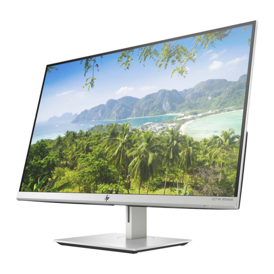
- Page 1 Maintenance and Service Guide U27 4k model L95468 SUMMARY This guide provides information about spare parts, removal and replacement of parts, diagnostic tests, problem troubleshooting, and more.
- Page 2 Devices, Inc. Bluetooth is a trademark owned sure to read “Important Safety Information”. by its proprietor and used by HP Inc. under license. NVIDIA is a trademark and/or registered trademark of NVIDIA Corporation in the U.S. and other countries. USB Type-C and USB-C are registered trademarks of USB Implementers Forum.
-
Page 3: Table Of Contents
Table of Contents 1 Getting started ................................1 Important safety information ..........................1 Important service information and precautions ....................1 RoHS (2002/95/EC) requirements .......................... 2 General descriptions .............................. 2 Firmware updates ..............................2 Before returning the repaired product to the customer ..................2 2 Monitor features ................................ -
Page 5: Getting Started
Getting started Read this chapter to learn about safety information and where to find additional HP resources. Important safety information Carefully read the cautions and notes within this document to minimize the risk of personal injury to service personnel. The cautions and notes are not exhaustive. Proper service methods are important to the safe, reliable operation of equipment. -
Page 6: Rohs (2002/95/Ec) Requirements
Level 2: Circuit board or standard parts replacement Firmware updates Firmware updates for the monitor are available at support.hp.com. If no firmware is posted, the monitor does not need a firmware update. Before returning the repaired product to the customer Perform an AC leakage current check on exposed metallic parts to be sure the product is safe to operate without the potential of electrical shock. -
Page 7: Monitor Features
Energy saver feature to meet requirements for reduced power consumption NOTE: For safety and regulatory information, refer to the Product Notices provided in your documentation kit. To access the latest user guide, go to http://www.hp.com/support, and follow the instructions to find your product. Then select User Guides. -
Page 8: Rear Components
Rear components To identify the components on the rear of the monitor, use this illustration and table. Table 1-1: Rear components and their descriptions Component Function Connect HDMI cables to the HDMI connectors on HDMI port source devices. Connects a DisplayPort cable to the DisplayPort DisplayPort connector connector on the source device. -
Page 9: Locating The Serial Number And Product Number
Depending on the product, the serial number and product number are located on a label on the rear of the monitor or on a label under the front bezel of the monitor head. You might need these numbers when contacting HP for support. For worldwide models (except India):... -
Page 10: Illustrated Parts Catalog
WIRELESS)ASS'Y REAR SUPPORT-R(ABS 94-HB/J13417B5)(ENCORE2-27F) REAR SUPPORT-L(ABS 94-HB/J13417B5)(ENCORE2-27F) MAC. SCREW-MI M3.0*4.0L, BLK-Ni MAC. SCREW-MRF M3.0*6.0L, BLK-Ni MAIN BD ASS'Y HP Beacon U27 4K Wireless (LM270WR3- RSAL1) HP Miracast WIFI Module PCBA 90*52mm LA46HD225-1H FOR DVT SHIELDING (SECC 0.5T)(HP U27 4k WIRELESS) PIFA Antenna 1.37RF for WLAN 802.11 a/b/g L64AT014-... -
Page 11: How To Order Parts
DISPLAY BD ASS'Y HP Beacon NECK(AL/Silver(SP-1430))(HP U27 4k WIRELESS)FULFIL BASE(ABS 94-HB/Silver(SP-1430))(HP U27 4k WIRELESS)FULFIL HDMI(2.0) CABLE 150mm (1P*#30+EAHM)*5+4C*#30+AEB AL 85% WH FFC 6P(0.5mm) 110mm(3FOLD+PRO)60V G/F (A8+A8) HF WH FFC 30P(0.5mm) 200mm(3FOLD+PRO+3M)60V G/F W/CONN*2+AL(AA) HF WH FFC 8P(0.5mm) 530mm(4FOLD+PRO)60V G/F (A8+A12/V-CUT) HF WH FFC 20P(0.5mm) 380mm(3FOLD+PRO)60V G/F... - Page 12 And it will be lower height than the surface of the rear cover DisplayPort &DC power: If use the DisplayPort connector (2041441-1) or the DC power connector (732-5935-ND), the layout of the PCB (printed wire board) needs to be modified. The pin distance is different compares to original connector, and it cannot fit I/O (input/output) hole.
- Page 13 You can purchase cables from the HP part store at https://partsurfer.hp.com/Search.aspx. NOTE: HP continually improves and changes product parts. For complete and current information about supported parts for your computer, go to http://partsurfer.com, select your country or region, and then follow the on-screen instructions.
-
Page 14: Removal And Replacement Procedures
Removal and replacement procedures Adherence to these procedures and precautions is essential for proper service. Preparation for disassembly Use this information to properly prepare to disassemble and reassemble the monitor. 1) Read the “Important safety information” and “Important service information and precautions” sections in the “Getting started”... - Page 15 1. Lay the display on soft desk and push the button of stand to unlock the stand, then pull out the stand form the monitor head. Push up the black button 2. Twist out the screw and separate base and stand. Twist out the screw EL-MF877-00 Page 11...
- Page 16 Strip the screws from rear cover, then move rear cover follow the below way. 4. Remove the acetate tapes and aluminum tape from the LVDS/ LED/Antenna cable.
- Page 17 5. Pull out the HDMI/LVDS/ LED/ 20 pin FFC/Antenna cable to panel. 6. Strip sixteen screws from the rear cover 、shielding and wifi board. EL-MF877-00 Page 13 Template Revision C Last revalidation date 13-April-2020 HPI instructions for this template are available at EL-MF877-01...
- Page 18 Remove two thermal Pad from MB. 8. Strip four screws from the shielding. remove 1PCS Thermal Pad,1PCS mylar and 1PCS Take out MB board from the shielding and aluminum tape. Remove 1PCS gasket block and 1PCS heat sink from miracast board...
-
Page 19: Connector Repair
Connector repair This procedure includes HDMI and DisplayPort connectors. The connectors are on the main board (board part number R352718220150 The connectors identifiers are as follows: Connector Location HDMI P200 DisplayPort P300 DC Power Audio In Audio out USB B type USB A type UP2/UP3/UP4 P200... -
Page 20: Hdmi Connector P200
HDMI connector P200 Repair the HDMI connector: 1) Use a soldering iron and a desoldering pump to remove as much solder as possible from the pin. 2) Use a hot air gun to melt the solder on the pins. 3) Lift the P200 connector from the PCB. 4) Place the new component on the PCB. -
Page 21: Dp Connector P300
DP connector P300 Repair the DP connector: 1) Use a soldering iron and a de-soldering pump to remove as much solder as possible from the pin. 2) Use a hot air gun to melt the solder on the pins. 3) Lift the P300 connector from the PCB. 4) Place the new component on the PCB. -
Page 22: Function Test
Function test After repair, be sure to confirm that all functions are working. Table 4-1: Function test Test item Operating description Operating description Tool used Tool used HDMI test Confirm whether image displays and sound plays correctly on Computer or DVD player the monitor. - Page 23 the input Image appears Brightness is too low. Open the OSD menu and blurred, select Brightness to adjust indistinct, or too the brightness scale as dark. needed. Check Video Monitor video cable is disconnected. Connect the appropriate Cable is displayed video signal cable between on screen.
-
Page 24: Index
Index components RC removal, 10 rear, 4 rear components, 4 connector repair, 15 removal features, 3 RC, 10 removal and replacement procedures, 10 firmware updates, 2 function test, 18 returning to customer, 2 how to order parts, 7 RoHS (2002/95/EC) requirements, 2 illustrated parts catalog, 6 safety information, 1 menu button location, 4... - Page 25 EL-MF877-00 Page 21 Template Revision C Last revalidation date 13-April-2020 HPI instructions for this template are available at EL-MF877-01...