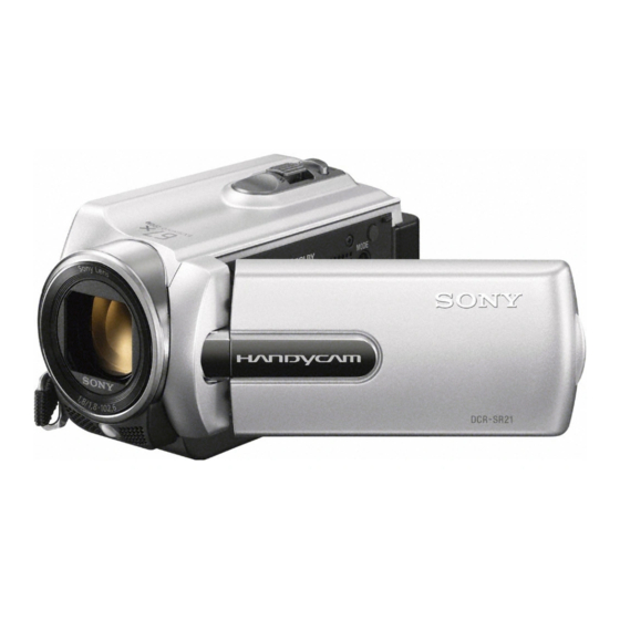
Sony DCR-SR21 Service Manual
Digital video camera recorder
Hide thumbs
Also See for DCR-SR21:
- User manual (101 pages) ,
- Operating manual (112 pages) ,
- Operating manual (116 pages)
Table of Contents
Advertisement
Quick Links
DCR-SR21/SR21E/SX21/SX21E
SERVICE MANUAL
Ver. 1.2 2012.05
Revised-2
Replace the previously issued
SERVICE MANUAL 9-834-601-32
with this Manual.
SERVICE NOTE (Check the following note before the service.)
– ENGLISH –
1-1. POWER SUPPLY DURING REPAIRS
1-2. PRECAUTION ON REPLACING THE VC-611 (F) / (H) BOARD
1-3. SELF-DIAGNOSIS FUNCTION
The components identified by
Les composants identifiés par
mark 0 or dotted line with mark
une marque 0 sont critiques pour
0 are critical for safety.
la sécurité.
Replace only with part number
Ne les remplacer que par une piè-
specified.
ce portant le numéro spécifié.
DCR-SR21/SR21E/SX21/SX21E_L2
9-834-601-33
Canadian Model
North European Model
Australian Model
Chinese Model
Argentine Model
Brazilian Model
Photo: DCR-SR21/Black
DIGITAL VIDEO CAMERA RECORDER
Ver.
Date
2
LEVEL
1.0
2011.08
1.1
2011.08
US Model
1.2
2012.05
AEP Model
UK Model
E Model
Sony Corporation
Revision History
History
Contents
Official Release
Revised-1
• Deletion of Canadian model in SR21 and Australian model in SX21E.
Page 2,
2-4
(A1 11-186)
Revised-2
• Correction of ACCESSORIES.
Page
2-9
(A2 12-075)
983460133.pdf
S.M. Rev.
issued
—
—
Yes
Yes
2012E08-1
© 2012.05
Published by Sony Techno Create Corporation
Advertisement
Table of Contents

Summary of Contents for Sony DCR-SR21
- Page 1 0 sont critiques pour 0 are critical for safety. la sécurité. Replace only with part number Ne les remplacer que par une piè- specified. ce portant le numéro spécifié. 2012E08-1 DCR-SR21/SR21E/SX21/SX21E_L2 © 2012.05 Sony Corporation 9-834-601-33 Published by Sony Techno Create Corporation...
-
Page 2: Specifications
DC 8.4 V (AC Adaptor) pack) DC 8.4 V (AC Adaptor) DCR-SR21E: 80 GB Mass (approx.): 170 g (6.0 oz) excluding the DCR-SR21: 80 GB Mass (approx.): 170 g (6.0 oz) excluding the Average power consumption: During camera Average power consumption: During camera “Memory Stick PRO Duo”... -
Page 3: Safety Check-Out
ARE CRITICAL TO SAFE OPERATION. REPLACE THESE COMPO- CRITIQUES POUR LA SÉCURITÉ DE FONCTIONNEMENT. NE REM- NENTS WITH SONY PARTS WHOSE PART NUMBERS APPEAR AS PLACER CES COMPOSANTS QUE PAR DES PIÈCES SONY DONT SHOWN IN THIS MANUAL OR IN SUPPLEMENTS PUBLISHED BY LES NUMÉROS SONT DONNÉS DANS CE MANUEL OU DANS LES... -
Page 4: Service Note
This ID has not been written in a new board for service, and therefore it must be entered after the board replacement. engineer engineer 31 ..Reload the tape. 31 ..Reload the tape. Start the Adjust Manual in the Adjust Station and execute the “USB SERIAL No. INPUT”. 32 ..Turn on power again. 32 ..Turn on power again. DCR-SR21/SR21E/SX21/SX21E_L2... - Page 5 Fault of writing to or erasing the flash memory. Inspect the flash memory (IC7801 on the VC-611 (F) /(H) board). Note 1 : Start the Adjust Manual in the Adjust Station and refer to the “DESTINATION DATA WRITE”. DCR-SR21/SR21E/SX21/SX21E_L2 1-2E...
-
Page 6: Repair Parts List
SX21/SX21E 3 Cabinet (G )Assy Front View Front View Right View Right View Bottom View Bottom View q; VC-611 (F)/(H) Board 1 F Panel Assy 7 Cabinet (R) Section • PD-426 Board • FP-1479 Flexible Board Link ACCESSORIES ASSEMBLY DCR-SR21/SR21E/SX21/SX21E_L2... -
Page 7: Note For Repair
• When remove a connector, don’t pull at wire of connector. It is possible that a wire is snapped. • When installing a connector, don’t press down at wire of connector. It is possible that a wire is snapped. • Do not apply excessive load to the gilded flexible board. DCR-SR21/SR21E/SX21/SX21E_L2... - Page 8 PANEL ASSY (S), F (SILVER) (Note 1) 3-080-204-21 SCREW, TAPPING, P2 A-1790-716-A CABINET (G (244)) ASSY (Note 2) A-1840-020-A CABINET (246) ASSY (B), TOP (BLACK) Note 2: Refer to "Assembly-1: Installation Cautions of DC-IN Harness". A-1840-021-A CABINET (246) ASSY (S), TOP (SILVER) DCR-SR21/SR21E/SX21/SX21E_L2...
- Page 9 (front 244) F panel assy 4-209-700-01 HOLDER, HDD 1-882-553-11 FP-1291 FLEXIBLE BOARD 2-635-562-31 SCREW (M1.7) Note 2: Direction of Installation of 11 Style Damper (1) as shown in the figure. 4-194-556-01 DAMPER (1), 11STYLE (Note 2) 3-080-204-21 SCREW, TAPPING, P2 DCR-SR21/SR21E/SX21/SX21E_L2...
- Page 10 Note 2: Refer to "Assembly-7: Installation Cautions of the 1-489-184-11 SWITCH BLOCK, CONTROL (PS24400) (SX21/SX21E) 2-635-562-31 SCREW (M1.7) Control Switch Block (PS24400) (SX21/SX21E)". (Note 2) 3-080-204-21 SCREW, TAPPING, P2 1-489-184-21 SWITCH BLOCK, CONTROL (PS24400) (SR21/SR21E) 4-209-702-01 CABINET (244), PS (SX21/SX21E) 4-209-703-01 CABINET (248), PS (SR21/SR21E) DCR-SR21/SR21E/SX21/SX21E_L2...
-
Page 11: Lens Section
MICROPHONE UNIT (Note 4) Note 4: Refer to "Assembly-5: Installation Cautions of Mic Unit.". 1-788-870-11 OPTICAL FILTER BLOCK (Note 2) 3-878-748-01 RUBBER (1340), SEAL 2-635-562-31 SCREW (M1.7) A-1790-893-A CD-801 BOARD, COMPLETE 2-660-401-01 SCREW (M1.7), NEW TRU-STAR, P2 3-080-204-21 SCREW, TAPPING, P2 DCR-SR21/SR21E/SX21/SX21E_L2... -
Page 12: Battery Panel Section
SCREW (M1.7) 4-209-729-01 SHEET METAL (244), BT (SX21/SX21E) 2-660-401-01 SCREW (M1.7), NEW TRU-STAR, P2 4-209-730-01 SHEET METAL (248), BT (SR21/SR21E) 1-822-470-61 JACK, DC (including BH901 and J901) (SX21/SX21E) 1-822-470-71 JACK, DC (including BH901 and J901) (SR21/SR21E) 4-209-728-01 PANEL, BT DCR-SR21/SR21E/SX21/SX21E_L2... -
Page 13: Cabinet (R) Section
COVER (M 246), HINGE 2-635-562-31 SCREW (M1.7) X-2582-029-1 HINGE ASSY, SIMO STYLE 2-660-401-01 SCREW (M1.7), NEW TRU-STAR, P2 1-471-504-11 MAGNET (ND5X3.5X2.4-B) (Note 1) 3-078-890-11 SCREW, TAPPING 4-282-731-01 COVER (C 246), HINGE (BLACK) 3-080-204-21 SCREW, TAPPING, P2 2-655-581-01 SCREW 0+P2 M1.7 NEWTRU-STAR SG DCR-SR21/SR21E/SX21/SX21E_L2... - Page 14 * 4-290-837-11 “Handycam” Handbook (PDF) (ENGLISH) Operating Instructions (PDF) for printing. (SR21E/SX21E) (Note2) ・ The printed matter is not supplied. If required, please order it with * 4-290-837-21 “Handycam” Handbook (PDF) (FRENCH) the part number below. (SR21E/SX21E) (Note2) DCR-SR21/SR21E/SX21/SX21E_L2 2-9E...
- Page 15 12.7mm Valley fold Diode (NSPL500DS) Adhesive tape 5.7mm Mountain fold Bend Precaution the polarity. Mountain Marks fold Libs Anode Speaker Marks Harness Valley fold Kathode 2 times Diode (NSPL500DS) VC-611 Board Unite corners. DCR-SR21/SR21E/SX21/SX21E_L2...
- Page 16 Assembly-7: Installation Cautions of the Control Switch Block (PS24400) (SX21/SX21E) Control Switch Block (PS24400) Routing the flexible board as shown. Flexible Board of the Control Switch Block (PS24400) DCR-SR21/SR21E/SX21/SX21E_L2 3-2E...


