Advertisement
Cool
Low
Heat
MODE
Dry
High
Auto
ON/OFF
Fan only
[1]
SPECIFICATION ...........................................1-1
[2]
ELECTRICAL PARTS.................................... 1-1
[3]
WIRING DIAGRAM ....................................... 1-2
[4]
EXTERNAL DIMENSION .............................. 1-3
[5]
PART NAMES ............................................... 1-4
CHAPTER 2. ATTENTION WHEN REPAIRING
[1]
HOW TO REPAIR REFRIGERATION ........... 2-1
Parts marked with "
" are important for maintaining the safety of the set. Be sure to replace these parts with specified ones for maintaining the
safety and performance of the set.
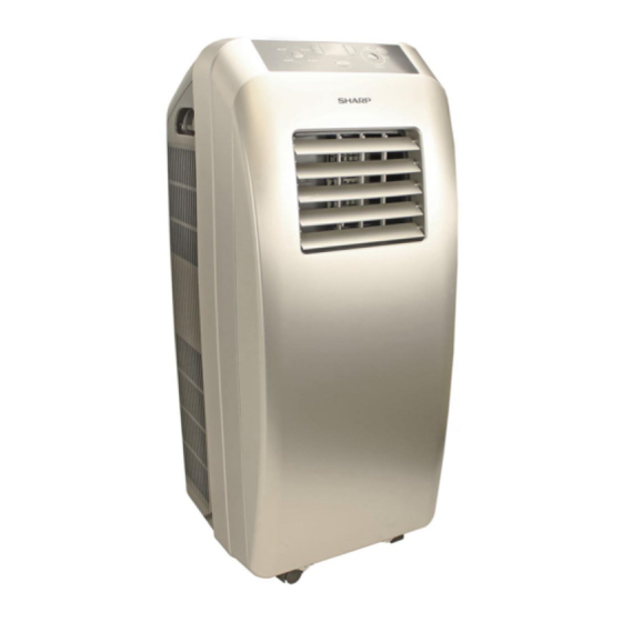
SERVICE MANUAL
PORTABLE AIR CONDITIONER
MODEL
In the interests of user-safety (Required by safety regulations in some countries) the set should
be restored to its original condition and only parts identical to those specified should be used.
CONTENTS
[1]
[2]
[1]
No. S1101CV10CTX
CV-10CTX-W
CV-10CTX-B
CV-10CTX-S
TROUBLESHOOTING........................... . ....... 3-1
FUNCTION............................................. . ....... 3-4
DISASSEMBLING PROCEDURE.......... . ....... 4-1
This document has been published to be used for
after sales service only.
The contents are subject to change without notice.
CV10CTX
Advertisement
Table of Contents

Related Manuals for Sharp CV-10CTX-W


Summary of Contents for Sharp CV-10CTX-W
-
Page 1: Table Of Contents
MODE High Auto ON/OFF Fan only CV-10CTX-W MODEL CV-10CTX-B CV-10CTX-S In the interests of user-safety (Required by safety regulations in some countries) the set should be restored to its original condition and only parts identical to those specified should be used. -
Page 2: Chapter 1. Product Specification [1] Specification
CV10CTX CHAPTER 1. PRODUCT SPECIFICATION [1] SPECIFICATION MODEL CV-10CTX-W CV-10CTX-B CV-10CTX-S Cooling Capacity BTU/h 10000 10000 10000 Electrical Data Phase Single Rated frequency Rated voltage Rated current Rated input 1250 1250 1250 BTU/Wh Noise level (Hi / Lo) dB (A) -
Page 3: Wiring Diagram
CV10CTX [3] WIRING DIAGRAM POWER BN(BK) TUBE TEMP. ROOM TEMP. TRANSFORMER SENSOR SENSOR BU(WH) WATER MOTOR YEGN(GN) TUBE ROOM TR-IN TR-OUT L(3) WATER(WATER1) COMP. C(T,U) K201 DISP2 MOTOR YEGN DISP2 COMP COMP(4) R(M,V) S(W,X) DISP1 ELECTRIC BOX DISP1 HIGH-WP YEGN WATER LEVEL MOTOR SWITCH... -
Page 4: External Dimension
CV10CTX [4] EXTERNAL DIMENSION Cool MODE SPEED Heat Auto High ON/OFF Fan only 15.5” Cool MODE Heat SPEED High Auto ON/OFF Fan only 13.4” Unit:inch... - Page 5 CV10CTX 3. Remote control 1. MODE Button:Press it to select operation mode(AUTO/COOL/DRY/FAN) 2. + Button : Press it to increase T-ONT-OFF AUTO temperature setting COOL SLEEP LOCK 3. Not available on this unit SPEED 4. TIMER Button: Press it set auto-on/auto- off timer ON/OFF MODE...
-
Page 6: Part Names
CV10CTX [5] PART NAMES 1. Front view 1 Control panel and display lamp 2 Remote control signal receiver window 3 Handel 4 Remote controller box 5 Air outlet 6 Vertical louvers 7 Horizontal louvers 8 Wheel 9 Air inlet 10 Grille 11 Air outlet 12 Air inlet 13 Power cord hook... -
Page 7: How To Repair Refrigeration
CV10CTX CHAPTER 2. ATTENTION WHEN REPAIRING [1] HOW TO REPAIR REFRIGERATION [1] HOW TO REPAIR REFRIGERATION Before sealed system work can be preformed a refrigerant recovery EPA and LOCALLY approved certification is required, additionally, EPA and LOCALLY approved refrigerant recovery equipment is required. 4. - Page 8 CV10CTX 6. Heating the tubing Direct the torch flame so that the larger tube receives most of the heat. Silver solder flows at 1200 F and silfos flows at 1300 F. OUTER CONE HOTTEST PART Heat all around the tubing. OF FLAME INNER CONE The flame is composed of two cones, a smaller inner cone (pale blue)
- Page 9 CV10CTX 8. Leaks Several methods are used to detect leaks in systems. ● Electronic Leak Detectors are very sensitive and are able to detect leaks down to 1/2 ounce per year. A good electronic leak detector is generally far better in locating very small leaks. ●...
-
Page 10: Chapter 3. Troubleshooting Guide [1] Troubleshooting
CV10CTX CHAPTER 3. TROUBLESHOOTING GUIDE [1] TROUBLESHOOTING 1. Failure for Temperature Sensor Main test point: ● If the outdoor environment temperature is in normal range ● If fan motor normally runs. ● If the radiating environment of indoor and outdoor unit is good Check the flow process of failure is: Energize and turn on the unit... - Page 11 CV10CTX 2. Failure for Switch of Water Level Main test point: ● If the defrosting tray is over-blow ● If the connection line of water level switch is good. ● If the water level switch is damaged. Check the flow process of failure is: Turn on the unit Display H8 Refer to the indication...
- Page 12 CV10CTX 3. Overcurrent Protection Start Normal fluctuation is within 10% of the rated voltage on the Is the supply voltage unstable with big fluctuation? Malfunction is eliminated. nameplate Is the supply voltage too low with overload? Adjust the supply voltage to maintain it within normal range Malfunction is eliminated.
-
Page 13: Function
CV10CTX [2] FUNCTION The temperature in this manual is expressed by Centigrade.If Fahrenheit is used, the switchover between them is Tf=TcX1.8+32. 4)Timer function 1.Temperature Parameters General Timer ◆ Indoor preset temperature (Tpreset) Timer ON can be set at unit OFF. If selected ON time is reached, ◆... -
Page 14: Chapter 4. Disassembling Procedure [1] Disassembling Procedure
CV10CTX CHAPTER 4. DISASSEMBLING PROCEDURE [1] DISASSEMBLING PROCEDURE "ACTUAL UNITS MAY VARY SLIGHTLY FROM THOSE PICTURES BELOW" CAUTION: ● DISCONNECT THE PORTABLE TYPE ROOM AIR CONDITIONER FROM THE POWER SUPPLY BEFORE ANY SERVICE. ● DISCONNECT THE EXHAUST HOSE FROM THE UNIT BEFORE ANY SERVICE.(SEE OPERATION MANUAL) ●... - Page 15 CV10CTX Steps Procedure 4.Remove rear board assy Remove the six screws fixing rear board, to rear board assy remove the rear board assy. panel sub-assy 5.Remove front panel sub-assy Remove the screws fixing the left, right and back side of the front panel, to remove the panel sub-assy.
- Page 16 CV10CTX Steps Procedure 8.Remove propeller cove r propeller cover Remove the screws fixing propeller cover, to remove the propeller cover. 9.Remove supporting board1 supporting board1 Remove the screw fixing supporting board to remove the board1. 10.Remove connection pipe Welding cut the joints on the connection pipe, to remove the connection pipe.
- Page 17 CV10CTX Steps Procedure 12.Remove air flue assy air flue assy Remove the four screws fixing air flue assy, to remove the air flue assy. 13.Remove upper propelle r Remove the four screws fixing upper propeller to upper propeller remove the upper propeller. 14.Remove upper centrifugal fan blade upper centrifugal Remove the screw nut and gasket fixing upper...
- Page 18 CV10CTX Procedure Steps 18.Remove motor water tray Take off the water tray, remove the three screws motor fixing motor, to remove the motor. supporting board 19.Remove water baffle and supporting board 2 3 water baffle Remove the screws fixing water baffle, to remove the water baffle.
-
Page 19: Parts Guide
In the interests of user-safety (Required by safety regulations in some countries) the set should be restored to its original condition and only parts identical to those specified should be used. CONTENTS CV-10CTX-W CV-10CTX-B CV-10CTX-S PACKAGE SUPPLIED ACCESSORIES Parts marked with "... - Page 20 Evaporator Assy [CV-10CTX-W CV-10CTX-S] 10 9JQ01006090 Evaporator Assy [CV-10CTX-B] 11 9JQ01406272 Electric Box Assy [CV-10CTX-W CV-10CTX-B CV-10CTX-S] 12 9JQ7671101601 Partition Pole (PC board) [CV-10CTX-W CV-10CTX-B CV-10CTX-S] 13 9JQ33000046 Capacitor CBB65 [CV-10CTX-W CV-10CTX-B CV-10CTX-S] 14 9JQ01406050 Electric Box Sub-Assy [CV-10CTX-W CV-10CTX-B CV-10CTX-S]...
- Page 21 Compressor and Fittings [CV-10CTX-W CV-10CTX-B CV-10CTX-S] 52 9JQ15006045 Motor Sub-assy(Flutter) [CV-10CTX-W CV-10CTX-B CV-10CTX-S] 53 9JQ10336003 Splash Water Flywheel [CV-10CTX-W CV-10CTX-B CV-10CTX-S] Motor holder (Shaded Pole Motor) [CV-10CTX-W CV-10CTX-B CV- 54 9JQ01706211 10CTX-S] 55 9JQ1501606201 Fan Motor [CV-10CTX-W CV-10CTX-B CV-10CTX-S] 56 9JQ76710291...
- Page 22 66 9JQ26116119 Flashing Board [CV-10CTX-W CV-10CTX-B CV-10CTX-S] 67 9JQ11126082 Fly Net [CV-10CTX-W CV-10CTX-B CV-10CTX-S] 68 9JQ26116114 Back Plate1(Single Wind Pipe) [CV-10CTX-W CV-10CTX-B CV-10CTX-S] 69 9JQ26116120 Baffle Plate(Air vent) [CV-10CTX-W CV-10CTX-B CV-10CTX-S] 70 9JQ26116132 Back Contact Card(Up) [CV-10CTX-W CV-10CTX-B CV-10CTX-S] 71 9JQ26116135...
- Page 23 PART PARTS CODE DESCRIPTION RANK MARK RANK [2] PACKAGE 78 9JQ52016090 Packaging Foam [CV-10CTX-W CV-10CTX-B CV-10CTX-S] 79 9JQ52016091 Packaging Foam [CV-10CTX-W CV-10CTX-B CV-10CTX-S] 80 9JQ51086105 Package Cushion [CV-10CTX-W CV-10CTX-B CV-10CTX-S] 81 9JQ51066125 Packaging Accessories [CV-10CTX-W CV-10CTX-B CV-10CTX-S] 82 9JQ63229939004 Inside Carton Box [CV-10CTX-W]...
- Page 24 Insect guard net Foam sael A 9JQ26116119 9JQ11126017 9JQ12126114 Foam seal B Screw(2) Bracket Power cord hook(2) Drain hose (adhesive) 9JQ70140554 9JQ02111151 9JQ7101600502[CV-10CTX-W] 9JQ05230013 9JQ121261141 9JQ7101600505[CV-10CTX-B] 9JQ71016005[CV-10CTX-S] Hose Clamp Hose clip(2) Rubber plug Battery(2) Manual Remote control 9JQ261160383 9JQ70810222 9JQ06816101 (AAA.
- Page 25 COPYRIGHT © 2011 BY SHARP CORPORATION ALL RIGHTS RESERVED. ALL RIGHTS RESERVED. No part of this publication may be reproduced, stored in retrieval systems, or transmitted in any form or by ALL RIGHTS RESERVED. any means, electronic, mechanical, photocopying, re-...