ABB M2306 User Manual
Lift control module
Hide thumbs
Also See for M2306:
- Online manual (28 pages) ,
- Product manual (29 pages) ,
- User manual (28 pages)
Table of Contents
Advertisement
Available languages
Available languages
Quick Links
Advertisement
Chapters
Table of Contents

Related Manuals for ABB M2306


Summary of Contents for ABB M2306
- Page 1 User manual M2306 & M2307, Lift control module Please select your language English Suomi Franç ais Norsk Polski Svenska Italiano Dansk Pусский Español 简体中文 Portuguê s Čeština Deutsch Slovenčina Nederlands...
- Page 2 VER:1.2 │ │ 29.07.2016 ABB-Welcome Pos : 2 /Di nA4 - Anleitung en Online/Inhalt/KN X/D oorEntr y/83220- AP- xxx/Titelbl att - 83220-AP- xxx - ABB @ 19\mod_1323249806476_15.doc x @ 111084 @ @ 1 Lift control module M2306 M2307 === Ende der Liste fü r T extmar ke Cover ===...
-
Page 3: Table Of Contents
Pos : 4 /Busch-J aeger (Neus truktur)/M odul-Str uktur/Online-Dokumentation/Inhal ts verz eic hnis (--> Fü r alle D okumente <--)/Inhalts verz eichnis @ 19\mod_1320649044386_15.doc x @ 109653 @ @ 1 Safety ......................3 Environment ....................3 ABB devices ................. 3 Technical data ....................4 Function ......................5 Connection .................... -
Page 4: Safety
ABB devices Pos : 13 /Busc h-J aeg er (Neustr uktur)/Modul- Struktur /Online-Dokumentati on/U mwel t (--> Fü r alle D okumente <--)/Hinweis e/Hi nweis - U mwelt - ABB El ektr ogeräte @ 19\mod_1323162745839_15.doc x @ 110867 @ @ 1 All packaging materials and devices from ABB bear the markings and test seals for proper disposal. -
Page 5: Technical Data
2 x 0.28 mm - 2 x 0.75 mm; Bus voltage 20-30 V DC Size 4 TE Protection IP 20 Operating -25 ° C - +55 ° C temperature M2306: 90 mm x 72 mm x 65 mm Size M2307: 216 mm x 110 mm x 45 mm... -
Page 6: Function
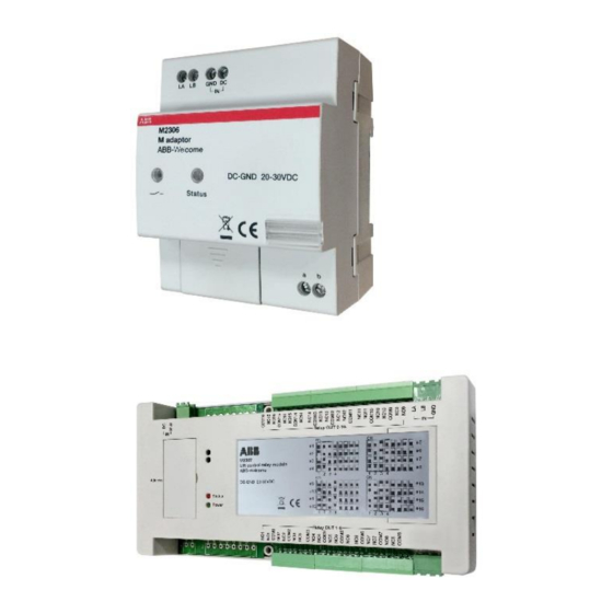
Pos : 22 /Busc h-J aeg er (Neustr uktur)/Modul- Struktur /Online-Dokumentati on/Übersc hriften (--> Fü r alle D okumente <--)/2. Ebene/G - L/Lastarten @ 20\mod_1326269704379_15.doc x @ 136905 @ 2 @ 1 The lift control modules include the M adaptor (M2306) and lift control relay module (M2307). These two devices together ensure that lift (elevator) only goes to authorized floor(s). -
Page 7: Connection
Pos : 30 /Busc h-J aeg er (Neustr uktur)/Modul- Struktur /Online-Dokumentati on/Übersc hriften (--> Fü r alle D okumente <--)/1. Ebene/A - F /Ansc hluss @ 19\mod_1309248278435_15.doc x @ 107413 @ 1 @ 1 Connection M2306 Pos : 31 /Busc h-J aeg er (Neustr uktur)/Modul- Struktur /Online-Dokumentati on/Ansc hluss/Di mmer /Ansc hlus s - 6591 U-101 @ 23\mod_1333093920008_15.doc x @ 207132 @ @ 1 Fig. - Page 8 - ON = Power on - OFF = Power off Setting LED - Blinks when working normally Address Set the module address The address range is 1-16.Only the left 4 bits are used. Power supply Connect with M2306 Connect with the lift controller...
- Page 9 ABB-Welcome Pos : 24 /Busc h-J aeg er (Neustr uktur)/Modul- Struktur /Online-Dokumentati on/Steuermodul e - Onli ne-D okumentation (--> F ü r all e D okumente <--)/++++++++++++ Seitenumbruc h ++++++++++++ @ 9\mod_1268898668093_0.doc x @ 52149 @ @ 1...
-
Page 10: Lift Control Relay Module Address By Binary Setting
ABB-Welcome Lift control relay module address by binary setting Fig. 3 Installer needs only read the labeling on the lift control module and adjust according to the given position. Only digits 1-2-3-4 are used. -
Page 11: Mounting / Installation
ABB-Welcome Mounting / Installation Pos : 34 /Busc h-J aeg er (Neustr uktur)/Modul- Struktur /Online-Dokumentati on/Sic herheit (--> Fü r alle Dokumente <--)/Warnhinweis e/Sic herheit - Ni eders pannungs- und 230 V-Leitungen @ 18 \mod_1302617821491_15.doc x @ 103465 @ @ 1... - Page 12 ABB-Welcome • Use suitable personal protective clothing. • Use only suitable tools and measuring devices. • Check the type of supply network (TN system, IT system, TT system) to secure the following power supply conditions (classic connection to ground, protective earthing, necessary additional measures, etc.).
-
Page 13: Mounting
The device must only be installed on mounting rails according to DIN E N 50022. It is highly recommended that M2306 be installed in the lift motor room on the top floor or the electrical riser, while M2307 should be installed in the lift cabin. -
Page 14: User Case
High building (no more than 16 floors) with one lift One M2306 and one M2307 Pos : 41 /Busc h-J aeg er (Neustr uktur)/Modul- Struktur /Online-Dokumentati on/Inbetri ebnahme/Di mmer/Inbetriebnahme - 6591 U-101 @ 19\mod_1311948781023_15.doc x @ 108300 @ 222 @ 1... - Page 15 ABB-Welcome Wiring with one M2306 and one M2307 Fig. 7...
-
Page 16: High Building (More Than 16 Floors) With One Lift
ABB-Welcome High building (more than 16 floors) with one lift one M2306 and multi (up to 16) M2307 Fig. 8: Topology... - Page 17 Fig. 9 Notes: 1.The first mini system controller (M2301) feeds one M2306 and one M2307. 2. An additional M2307 should be locally powered by one mini system controller. Eg. with (4) M2307 and (1) M2306, 4 mini system controllers are needed.
-
Page 18: High Building (More Than 16 Floors) With Two Lifts
ABB-Welcome High building (more than 16 floors) with two lifts one M2306 and multi M2307 support 2 lifts Fig. 10: Topology Note: The address code can not be repeated. -
Page 19: High Building (More Than 16 Floors) With Four Lifts
ABB-Welcome High building (more than 16 floors) with four lifts Two M2306 and multi M2307 support 4 lifts Fig. 11: Topology Pos: 42 /Busch-Jaeger (Neustruktur)/Modul-Struktur/Online-Dokumentation/Steuermodule - Online- Dokumentation (--> Für alle Dokumente <--)/++++++++++++ Seitenumbruch ++++++++++++ @ 9\mod_1268898668093_0.docx @ 52149 @ @ 1... -
Page 20: Operation
User scenario illustration of visitor target floor 5. The visitor 2. The resident presses the "unlock" button reaches the at any ABB-Welcome indoor station. 12th floor. 4. Within a set of time (default of 10 minutes), the visitor can only activate the 12th floor. -
Page 21: User Scenario Illustration Of Resident Target Floor
ABB-Welcome Pos : 43 /Busc h-J aeg er (Neustr uktur)/Modul- Struktur /Online-Dokumentati on/Übersc hriften (--> Fü r alle D okumente <--)/1. Ebene/A - F /Bedienung @ 11\mod_1279185541649_15.doc x @ 83043 @ 1 @ 1 Pos : 44 /Busc h-J aeg er (Neustr uktur)/Modul- Struktur /Online-Dokumentati on/Bedienung/Di mmer/Bedi enung - 6591 U-101 @ 23\mod_1333091293158_15.doc x @ 207069 @ @ 1 User Scenario Illustration of resident target floor 4. -
Page 22: Configuration Through Pc Software
Connected to PC During configuration, the lift control adaptor can be connected directly to the PC so that the installed software (ABB-Welcome PC Configuration Tool) can be used. Essentially, there is no need for local power supply during configuration. Upon completing configuration, click "Send the Configuration" to upload the configured file to the system. -
Page 23: Configuration
ABB-Welcome Configuration Basic Steps Step 1: Set basic parameters of the apartment using the ABB-Welcome configuration tool. Fig. 15 Function Select building number. Select floor number. Select apartment number. Set physical address (e.g., 13 means the IS address set by IS switches) Set user name Set logic address (e.g., 0703 means 7th floor, apartment number 3). - Page 24 ABB-Welcome Step 2: Select building, M2307 and configure parameters of each relay Fig. 16 Function Select building number Select M2307 number Click “Add” to add a new M2307 Select ON or OFF for connecting the relay Select NO or NC for output type...
- Page 25 Select outdoor station number Select Relay No. of M2307 Click “Add” to associate outdoor station with relay Send all parameters to M2306 Input password*. Default password is 123456. *Please write down this password. If password is forgotten, software must be reloaded.
- Page 26 Building number (same as step2) Select indoor station physical address Select relay number of M2307 Select outdoor station number (floor number of outdoor station installed) Click “Add” to associate indoor station with relay Send all parameters to M2306 Input password. Default password is 123456.
- Page 27 ABB-Welcome Optional steps: Step 5: Export all data from this project or import data for new project Fig. 19 Function Export all lift control configuration data to one read-only Excel file. (Export the lift control configuration of each building for future reference.)
- Page 28 ABB-Welcome Step 6: Save as one new project Fig. 20 Function Save as one new project: *.xml...
- Page 29 ABB-Welcome Step 7: Import existing project data to new outdoor station, guard unit and lift control Fig. 21 Function Open one existing project: *.xml...
- Page 30 We reserve the right to, at any time, make technical changes or changes in the content of this document without prior notice. The detailed specifications agreed to at the time of ordering applies to all orders. ABB accepts no responsibility for possible errors or incompleteness in this document.
- Page 31 VER:1.0 │ │ 20.10.2015 ABB-Welcome Поз. 2 /Di nA4 - Anleitungen Online/Inhal t/KN X/D oorEntr y/83220- AP- xxx/Titelbl att - 83220-AP- xxx - ABB @ 19\mod_1323249806476_15.doc x @ 111084 @ @ 1 Модуль управления лифтом M2306 M2307 === Ende der Liste fü r T extmar ke Cover ===...
- Page 32 Монтаж / установка ..................10 Требования к квалификации электрика ........10 Монтаж..................12 Пользовательский вариант ............... 13 Один M2306 и M2307 ..............13 Один M2306 и M2307 ..............15 До двух лифтов на здание ............17 До четырех лифтов на здание ..........18 Эксплуатация...
-
Page 33: Безопасность
Устройства ABB Поз. 13 /Bus ch-J aeg er (Neustr uktur)/Modul-Struktur/Online-Dokumentati on/U mwel t (--> Fü r alle Dokumente <--)/Hi nweis e/Hi nweis - U mwelt - ABB El ektr oger ä te @ 19\mod_1323162745839_15.doc x @ 110867 @ @ 1 Все... -
Page 34: Технические Данные
Напряжение на 20–30 В пост. тока шине Размер 4 TE Класс защиты IP20 Рабочая -25 ° C – +55 ° C температура M2306: 90 x 72 x 65 мм Размер M2307: 216 x 110 x 45 мм — 4 —... -
Page 35: Функция
Поз. 22 /Bus ch-J aeg er (Neustr uktur)/Modul-Struktur/Online-Dokumentati on/Ü bersc hriften (--> Fü r alle D okumente <--)/2. Ebene/G - L/Lastarten @ 20\mod_1326269704379_15.doc x @ 136905 @ 2 @ 1 В модули управления лифтом входят переходное устройство М (M2306) и модуль реле... -
Page 36: Соединение
Поз. 30 /Bus ch-J aeg er (Neustr uktur)/Modul-Struktur/Online-Dokumentati on/Ü bersc hriften (--> Fü r alle D okumente <--)/1. Ebene/A - F/Ansc hluss @ 19\mod_1309248278435_15.doc x @ 107413 @ 1 @ 1 Соединение M2306 Поз. 31 /Bus ch-J aeg er (Neustr uktur)/Modul-Struktur/Online-Dokumentati on/Ansc hl uss/Di mmer/Ansc hlus s - 6591 U-101 @ 23\mod_1333093920008_15.doc x @ 207132 @ @ 1 Рис. - Page 37 - Не горит - питание выключено Индикатор настройки - Вспыхивает во время нормальной работы Адрес Установка адреса модуля Диапазон адресов от 1 до 16, используются только 4 левые бита. Источник питания Подключить к модулю M2306 Подключить к контроллеру лифта — 7 —...
- Page 38 ABB-Welcome Различный режим работы в соответствии с настройками программного обеспечения ПК Поз. 24 /Bus ch-J aeg er (Neustr uktur)/Modul-Struktur/Online-Dokumentati on/Steuermodul e - Onli ne-D okumentation (--> F ü r all e D okumente <--)/++++++++++++ Seitenumbruch ++++++++++++ @ 9\mod_1268898668093_0.doc x @ 52149 @ @ 1 Если...
- Page 39 ABB-Welcome 5.2.2 Адрес модуля реле управления лифтом по двоичной настройке Рис. 3 Монтажнику необходимо только прочитать табличку на модуле управления лифтом и выполнить регулировку в соответствии с заданным положением. Используются только цифры 1, 2, 3, 4. — 9 —...
-
Page 40: Монтаж / Установка
ABB-Welcome Монтаж / установка Поз. 34 /Bus ch-J aeg er (Neustr uktur)/Modul-Struktur/Online-Dokumentati on/Sic herheit (--> Fü r all e Dokumente <--)/Warnhinweis e/Si cherheit - Ni eders pannungs- und 230 V-Leitung en @ 18\mod_1302617821491_15.doc x @ 103465 @ @ 1 Предупреждение! Электрическое... - Page 41 ABB-Welcome Примите меры от случайного включения. Убедитесь в отсутствии напряжения. Подключите заземление. Накрывайте соседние детали, находящие под напряжением, или устанавливайте для них ограждение. • Пользуйтесь подходящей защитной одеждой. • Используйте только подходящие инструменты и измерительные устройства. • Проверяйте тип электросети (TN-, IT-, TT-система), чтобы...
-
Page 42: Монтаж
Устройство необходимо устанавливать только на монтажные рейки в соответствии с DIN EN 50022. Модуль M2306 настоятельно рекомендуется для установки в помещении с двигателями лифта на верхнем этаже или электрического вертикально проложенного кабеля; в то время как модуль M2307 настоятельно рек омендуется... -
Page 43: Пользовательский Вариант
ABB-Welcome Пользовательский вариант Один M2306 и M2307 Высотное здание не более 16 этажей с одним лифтом Переходное устройство Поз. 41 /Bus ch-J aeg er (Neustr uktur)/Modul-Struktur/Online-Dokumentati on/Inbetri ebnahme/Di mmer /Inbetriebnahme - 6591 U-101 @ 19\mod_1311948781023_15.doc x @ 108300 @ 222 @ 1 Рис. - Page 44 ABB-Welcome Проводка с помощью одного модуля M2306 и M2307 Рис. 7 — 14 —...
- Page 45 ABB-Welcome Один M2306 и M2307 Высотное здание более 16 этажей с одним лифтом Переходное устройство Системный мини- контроллер (M2301) Рис. 8: Топология — 15 —...
- Page 46 ABB-Welcome Рис. 9 Примечания: 1. Первый системный мини-контроллер (M2301) питает M2306 и один M2307. 2. Любой дополнительный модуль M2307 должен питаться локально от одного системного мини-контроллера. Например, 4 M2307 + 1 M2306, всего, необходимо 4 системных мини-контроллера. — 16 —...
-
Page 47: До Двух Лифтов На Здание
ABB-Welcome До двух лифтов на здание Высотное здание более 16 этажей Переходное устройство Рис. 10: Топология Примечание: Код адреса не может повторяться. — 17 —... -
Page 48: До Четырех Лифтов На Здание
ABB-Welcome До четырех лифтов на здание Высотное здание более 16 этажей Переходное устройство Переходное устройство Рис. 11: Топология Поз. 42 /Busch-Jaeger (Neustruktur)/Modul-Struktur/Online-Dokumentation/Steuermodule - Online- Dokumentation (--> Für alle Dokumente <--)/++++++++++++ Seitenumbruch ++++++++++++ @ 9\mod_1268898668093_0.docx @ 52149 @ @ 1 Примечание: Код адреса не может повторяться. -
Page 49: Эксплуатация
ABB-Welcome Поз. 43 /Bus ch-J aeg er (Neustr uktur)/Modul-Struktur/Online-Dokumentati on/Ü bersc hriften (--> Fü r alle D okumente <--)/1. Ebene/A - F/Bedienung @ 11\mod_1279185541649_15.doc x @ 83043 @ 1 @ 1 Эксплуатация Поз. 44 /Bus ch-J aeg er (Neustr uktur)/Modul-Struktur/Online-Dokumentati on/Bedienung/Di mmer /Bedi enung - 6591 U-101 @ 23\mod_1333091293158_15.doc x @ 207069 @ @ 1 Рисунок... -
Page 50: Рисунок Пользовательского Сценария Нужного Для Жильца Этажа
ABB-Welcome Поз. 43 /Bus ch-J aeg er (Neustr uktur)/Modul-Struktur/Online-Dokumentati on/Ü bersc hriften (--> Fü r alle D okumente <--)/1. Ebene/A - F/Bedienung @ 11\mod_1279185541649_15.doc x @ 83043 @ 1 @ 1 Поз. 44 /Bus ch-J aeg er (Neustr uktur)/Modul-Struktur/Online-Dokumentati on/Bedienung/Di mmer /Bedi enung - 6591 U-101 @ 23\mod_1333091293158_15.doc x @ 207069 @ @ 1 Рисунок... -
Page 51: Конфигурация С Помощью Программного Обеспечения Пк
Во время конфигурации переходное устройство управления лифтом можно непосредственно подключить к ПК, на котором может использоваться установленное программное обеспечение (программа конфигурации ABB Welcome M на ПК). Другими словами, во время конфигурации локального источника питания не требуется. По завершению конфигурации нажмите кнопку Send the Configuration (Отправить... -
Page 52: Конфигурация
ABB-Welcome Конфигурация Основные шаги Шаг 1. Установка основных параметров подъезда с помощью программы конфигурации Welcome M Рис. 15 № Функция Выбрать номер здания. Выбрать номер этажа. Выбрать номер подъезда. Установить физический адрес (например 13 означает адрес АТ, установленный с помощью переключателей АТ) Задать... - Page 53 ABB-Welcome Шаг 2. Выбрать здание, модуль М2307 и настроить параметры каждого реле Рис. 16 № Функция Выбор номера здания. Выбор номера модуля М2307. Нажать кнопку Add (Добавить), чтобы добавить новый модуль М2307 Выбрать ON (ВКЛ.) или OFF (ВЫКЛ.) для подключения реле...
- Page 54 ABB-Welcome Шаг 3. Связать ВС с модулем M2307 Рис. 17 № Функция Номер здания (как в шаге 2) Выбрать номер ВС Выбрать номер реле модуля М2307 Нажать кнопку Add (Добавить), чтобы связать ВС с реле Передать все параметры в модуль М2306 Ввести...
- Page 55 ABB-Welcome Шаг 4. Связать АТ с модулем M2307 Рис. 18 № Функция Номер здания (как в шаге 2) Выбрать физический адрес АТ Выбрать номер реле модуля М2307 Выбрать номер ВС (номер этажа установленной ВС) Нажать кнопку Add (Добавить), чтобы связать АТ с реле...
- Page 56 ABB-Welcome Дополнительные шаги: Шаг 5. Экспортировать все данные этого проекта или импортировать данные для нового проекта Рис. 19 № Функция Экспортировать все конфигурационные данные управления лифтом в один файл *.xls (только для чтения) (Экспортировать конфигурацию управления лифтом каждого здания после того, как конфигурация будет передана для последующего...
- Page 57 ABB-Welcome Шаг 6. Сохранить в качестве одного нового проекта Рис. 20 № Функция Сохранить в качестве одного нового проекта: *.xml — 27 —...
- Page 58 ABB-Welcome Шаг 7. Открыть данные одного существующего проекта в новой ВС, станции безопасности и модуле управления лифтом Рис. 21 № Функция Открыть один существующий проект: *.xml — 28 —...