
Related Manuals for Beko BEKOMAT 33iU


Summary of Contents for Beko BEKOMAT 33iU
- Page 1 Original installation and operation manual BEKOMAT 33iU / 33iU CO ® > BM33iU > BM33iU CO 01-4244...
-
Page 2: Table Of Contents
BEKOMAT ® 33iU / 33iU CO Original installation and operation manual Table of contents 1. Notes about the documentation .....................5 1.1 Contact ............................5 1.2 Information about this installation and operation manual .............5 2. Safety ..............................6 2.1 Use .............................6 2.1.1 Intended use ............................6 2.1.2 Reasonably foreseeable inappropriate use ................. - Page 3 Original installation and operation manual BEKOMAT 33iU / 33iU CO ® 4. Technical data ..........................23 4.1 Operating parameters ......................23 4.2 Storage and transportation parameters ................24 4.3 Materials ..........................24 4.4 Dimensions ..........................24 4.5 Screw fastening torques ......................25 4.6 Installation dimensions ......................
- Page 4 BEKOMAT ® 33iU / 33iU CO Original installation and operation manual Table of contents 11. Consumables, accessories and spare parts ................55 11.1 Order information ........................ 55 11.2 Accessories ........................... 55 11.3 Spare parts..........................56 12. Decommissioning ........................57 12.1 Warning notices ........................57 12.2 Decommissioning work .......................
-
Page 5: Notes About The Documentation
This documentation contains all the necessary steps for use of the product and the accessories. 1.1 Contact Manufacturer Customer service and tools BEKO TECHNOLOGIES GmbH BEKO TECHNOLOGIES GmbH Im Taubental 7 | 41468 Neuss Im Taubental 7 | 41468 Neuss Tel. -
Page 6: Safety
• Only combine the product and accessories with the products and components named and recommended by BEKO TECHNOLOGIES in the manual. • Adhere to the prescribed maintenance schedule. Before using the product and the accessories, the operating company must make sure that all conditions and prerequisites for intended use are given. -
Page 7: Reasonably Foreseeable Inappropriate Use
Original installation and operation manual BEKOMAT 33iU / 33iU CO ® 2.1.2 Reasonably foreseeable inappropriate use Reasonably foreseeable inappropriate use is deemed to have occurred if the product or the accessories are used in any other way than that described in the chapter "Intended use". Reasonably foreseeable inappropriate use includes the use of the product or the accessories in a manner not intended by the manufacturer or supplier but which may result from foreseeable human behaviour. -
Page 8: Target Group And Personnel
BEKOMAT ® 33iU / 33iU CO Original installation and operation manual 2.3 Target group and personnel This manual addresses the personnel listed below who are involved with work on the product or the accessories. INFORMATION Personnel requirements! The personnel may not execute any actions on the product or the accessories when they are under the influence of drugs, medications, alcohol or other substances that may impair their ... -
Page 9: Explanation Of The Safety Symbols Used
Original installation and operation manual BEKOMAT 33iU / 33iU CO ® 2.4 Explanation of the safety symbols used The symbols used below indicate safety-relevant and important information which must be adhered to when handling the product and to ensure safe and optimum operation. Symbol Description / explanation General warning symbol (danger, warning, caution) -
Page 10: Safety And Warning Notices
BEKOMAT ® 33iU / 33iU CO Original installation and operation manual 2.5 Safety and warning notices This chapter provides an overview of all the important safety aspects for personal protection as well as for the safe and problem-free operation of the product and accessories. The following chapters list the dangers posed by this product and the accessories even with intended use. -
Page 11: Electric Voltage
Original installation and operation manual BEKOMAT 33iU / 33iU CO ® 2.5.3 Electric voltage Contact with live components may result in serious personal injuries or death. To ensure the safe handling of live components, observe the following points: • Set up a safety area around the working area during all installation and repair work. •... -
Page 12: Maintenance
• Dispose of electrical and electronic components through a specialist waste disposal company or return to BEKO TECHNOLOGIES. 2.5.7 Handling hazardous substances Contact with condensate containing substances which endanger health and the environment can pose a health hazard, causing irritation and/or damage to the eyes, skin and mucous membranes. In addition, polluted condensate must be ... -
Page 13: Use Of Spare Parts, Accessories Or Materials
Original installation and operation manual BEKOMAT 33iU / 33iU CO ® 2.5.8 Use of spare parts, accessories or materials The use of incorrect spare parts, accessories or materials, as well as auxiliary and operating materials, may result in death or serious injury. Malfunction and device failure as well as material damage can occur. •... -
Page 14: Product Information
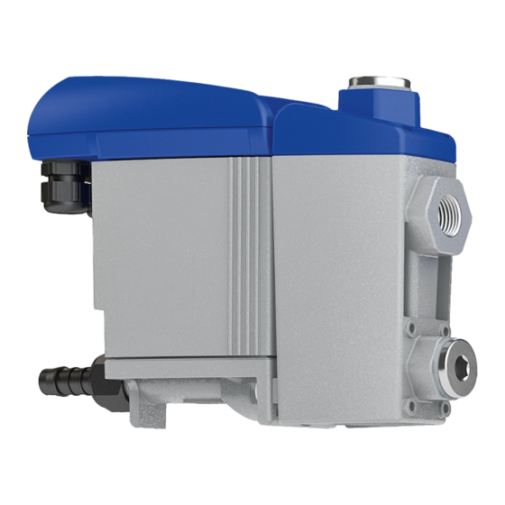
BEKOMAT ® 33iU / 33iU CO Original installation and operation manual 3. Product information 3.1 Product overview Item Description / explanation Item Description / explanation Condensate inlet (only when a venting line is Control unit, complete used at the same time) Control panel Condensate discharge Condensate inlet, vertical... -
Page 15: Exploded Drawing
Original installation and operation manual BEKOMAT 33iU / 33iU CO ® 3.2 Exploded drawing Item Description / explanation Item Description / explanation Screw M3.5 x 10 [13] O-ring 18.5 x 2 mm Top cover [14] Condensate collecting container Moulded seal [15] Flat gasket Sensor board... -
Page 16: Function Description
BEKOMAT ® 33iU / 33iU CO Original installation and operation manual 3.3 Function description Illustration Description / explanation The condensate flows via the vertical condensate inlet [C] or the horizontal condensate inlet [D] into the BEKOMAT and collects in the collecting container [K]. ® The filling level in the collecting tank [K] is continuously monitored by a capacitive sensor in the sensor tube [L]. -
Page 17: Modbus Function
Original installation and operation manual BEKOMAT 33iU / 33iU CO ® 3.4 Modbus function The BEKOMAT has an integrated Modbus which can be used to read out the operating parameters and device ® information. The BEKOMAT is operated using the client-server system with operating mode Modbus-RTU. ®... -
Page 18: Read Input Registers (0X04)
BEKOMAT ® 33iU / 33iU CO Original installation and operation manual 3.4.3.1 Read Input Registers (0x04) Modbus Contents Description / explanation Data type address 1116 Main Timer Hi-Word Operating hours counter [h] 1117 Main Timer Lo-Word 1102 Main Counter Hi-Word Counter for switching cycles 1103 Main Counter Lo-Word... -
Page 19: Read Device Identification (0X2B / 0X0E)
Item name Object (Modbus Description / explanation Examples Format specification) 0x00 VendorName Manufacturer BEKO TECHNOLOGIES ASCII BEKO material number circuit 0x01 ProductCode 04023034 ASCII board 0x02 MajorMinorRevision Software version numbers* APP V2.3.0 BBS V3.4.0 CFG V1.0.0 ASCII http://www.beko-technologies. 0x03... -
Page 20: Changing Interface Parameters
The software can be downloaded from the BEKO TECHNOLOGIES homepage (see “1.1 Contact” on page 5). To connect to a PC, BEKO TECHNOLOGIES recommends using the Integrator Hardware Kit (for ordering information, see chapter “11.2 Accessories” on page 55). -
Page 21: Error Messages
+1 ... +70 °C / +34 ... +158 °F IP67 4046924 24 VDC ± 10% <3 W 0,8 ... 16 barg / 12 ... 230 psig 14345535 Manufacturer: BEKO TECHNOLOGIES GMBH 4046924 14345535 Made in Germany Example illustration Item Description / explanation... -
Page 22: Scope Of Delivery
BEKOMAT ® 33iU / 33iU CO Original installation and operation manual 3.6 Scope of delivery The table below shows the scope of delivery of the BEKOMAT ® Illustration Description / explanation BEKOMAT 33iU / 33iU CO ® Original installation and operation manual Original Installations- und Betriebsanleitung BEKOMAT ®... -
Page 23: Technical Data
Original installation and operation manual BEKOMAT 33iU / 33iU CO ® 4. Technical data 4.1 Operating parameters BEKOMAT 33iU 33iU CO ® Ambient relative humidity 10 … 80 %, without condensation 2000 m Maximum operating height 2187.23 yd 0.8 … 16 bar(g) Minimum / maximum operating pressure 12 …... -
Page 24: Storage And Transportation Parameters
BEKOMAT ® 33iU / 33iU CO Original installation and operation manual 4.2 Storage and transportation parameters BEKOMAT 33iU 33iU CO ® Minimum / maximum temperature, +1 … +70 °C storage and transportation +34 … +158 °F 4.3 Materials BEKOMAT 33iU 33iU CO ® Aluminium Aluminium, hardcoated Housing... -
Page 25: Screw Fastening Torques
Original installation and operation manual BEKOMAT 33iU / 33iU CO ® 4.5 Screw fastening torques Item Description / explanation Fastening torques [Z1] Locking screw, condensate inlet 35 Nm +2 Nm (25.82 ft-lb +1.46 ft-lb) [Z2] Screws, mounting brackets (optional) 8 Nm +2 Nm (5.9 ft-lb +1.46 ft-lb) [Z3] Hose connection, condensate discharge 3 …... -
Page 26: Installation Dimensions
BEKOMAT ® 33iU / 33iU CO Original installation and operation manual 4.6 Installation dimensions Illustration Description / explanation Allow sufficient assembly space above the top cover at the place of installation so that the LEDs are visible and the TEST button can be pressed. 4.7 Terminal diagram Illustration GND / 0V RS485 - B RS485 - A +24 V... -
Page 27: Transport And Storage
5.1 Transport After transporting and removing the packaging material, inspect the product for possible transport damage. If you find such damage, notify the carrier company, BEKO TECHNOLOGIES or one of its agents immediately. Transport the product as follows: • Only transport the product in its original packaging. -
Page 28: Assembly
BEKOMAT ® 33iU / 33iU CO Original installation and operation manual 6. Assembly 6.1 Warning notices DANGER Use of incorrect spare parts, accessories or materials! The use of incorrect spare parts, accessories or materials, as well as auxiliary and operating materials, may result in death or serious injury. -
Page 29: Assembly Conditions
Original installation and operation manual BEKOMAT 33iU / 33iU CO ® 6.2 Assembly conditions Wrong Right Description / explanation > 3% Continuous slope > 3 % in hoses • When using hoses as the feed line, ensure a continuous slope > 3 %. •... - Page 30 BEKOMAT ® 33iU / 33iU CO Original installation and operation manual Wrong Right Description / explanation Manifold design • The cross-section of the manifold must be at least equal to the sum of the individual cross- sections of the connected feed lines. •...
-
Page 31: Assembly Work
Original installation and operation manual BEKOMAT 33iU / 33iU CO ® Wrong Right Description / explanation Discharge from pressurised pipes • Divert the flow of gas to provide a deflecting surface to discharge the fluid components in the gas. 6.3 Assembly work For assembly work to be carried out, the following prerequisites must be fulfilled and the preparatory tasks must have been completed. Prerequisites Tools Material Protective equipment • Spanner or adjustable end wrench •... - Page 32 BEKOMAT ® 33iU / 33iU CO Original installation and operation manual Assembly work Illustration Description / explanation Horizontal connection of the condensate inlet line 1. Remove the plugs [17, 10] on the condensate inlet [D] and condensate discharge [F]. Vertical connection of the condensate inlet line 1.
- Page 33 Original installation and operation manual BEKOMAT 33iU / 33iU CO ® Assembly work Illustration Description / explanation Recommendation: To ensure easy maintenance of the product, install a shut- off valve [X2] in the condensate inlet line [X1]. 3. For the condensate inlet line [X1], apply sealant to the end of a pressure-resistant pipe and screw this in at the condensate inlet [C].
-
Page 34: Electrical Installation
BEKOMAT ® 33iU / 33iU CO Original installation and operation manual 7. Electrical installation 7.1 Warning notices DANGER Use of incorrect spare parts, accessories or materials! The use of incorrect spare parts, accessories or materials, as well as auxiliary and operating materials, may result in death or serious injury. -
Page 35: Connection Work
Original installation and operation manual BEKOMAT 33iU / 33iU CO ® NOTE Electromagnetic interference! Electromagnetic faults caused by high-voltage cables, switchgears and high-frequency switching components, in particular speed-controlled and frequency-controlled drives (VSD/ VFD) can interfere with the operation of electronic devices and communication between electronic devices. • Mount electronic devices far away from high voltage cables, switching systems and high- frequency switching components. - Page 36 BEKOMAT ® 33iU / 33iU CO Original installation and operation manual Connection work - single device Illustration Description / explanation 3. Unscrew the counter nut [6] from the right cable gland [G]. 4. Remove the plugs [7] from the counter nut [6]. 50 mm (1.97 in) 6 mm...
-
Page 37: Connecting Multiple Modbus Devices (Series Connection)
Original installation and operation manual BEKOMAT 33iU / 33iU CO ® Connection work - single device Illustration Description / explanation 11. Set the top cover [2] in place and insert the screws [1]. 12. Tighten the screws [1] with a torque of 0.9 Nm +0.5 Nm (0.66 ft-lb +0.37 ft-lb). - Page 38 BEKOMAT ® 33iU / 33iU CO Original installation and operation manual Connection work - series connection Illustration Description / explanation 6. Fit the counter nuts [6] over the connection cable [X5] and insert connection cable [X6]. 7. Insert the connection cable [X5] into the left cable gland [H].
-
Page 39: Commissioning
Original installation and operation manual BEKOMAT 33iU / 33iU CO ® 8. Commissioning 8.1 Warning notices DANGER Operation outside the permissible limit range! Operation of the product and accessories outside the permissible limits and operating parameters, unauthorised intervention and modifications may result in death or serious injury. • Adhere to the limits and operating parameters specified on the type plate and in the manual. •... -
Page 40: Commissioning Work
BEKOMAT ® 33iU / 33iU CO Original installation and operation manual 8.2 Commissioning work Illustration Description / explanation 1. Connect the voltage supply. 0 The BEKOMAT carries out the power-on self-test. ® 2. Slowly pressurise the system (e.g. by slowly opening the recommended shut-off valve [X2] in the condensate inlet line [X1]). -
Page 41: Operation
Original installation and operation manual BEKOMAT 33iU / 33iU CO ® 9. Operation 9.1 Warning notices DANGER Operation outside the permissible limit range! Operation of the product and accessories outside the permissible limits and operating parameters, unauthorised intervention and modifications may result in death or serious injury. • Adhere to the limits and operating parameters specified on the type plate and in the manual. •... -
Page 42: Operating States
BEKOMAT ® 33iU / 33iU CO Original installation and operation manual 9.2 Operating states Illustration Description / explanation Disconnected Alarm TEST Power Service • All LEDs are off Switch on / power-on self-test Alarm • All LEDs are on for 1 second TEST Power Service •... - Page 43 Original installation and operation manual BEKOMAT 33iU / 33iU CO ® Illustration Description / explanation Discharge procedure (TEST button pressed briefly) Alarm • The red ALARM LED is off TEST Power Service • The green POWER LED is on (100 % brightness) while the solenoid valve is cycling n = ∞...
-
Page 44: Maintenance
BEKOMAT ® 33iU / 33iU CO Original installation and operation manual 10. Maintenance 10.1 Warning notices DANGER Pressurised system! Danger of death or serious personal injury through contact with quickly or suddenly escaping fluids or through bursting system parts. • All maintenance and repair work on the system must be carried out in the depressurised state and with the system secured against unintentional pressurisation. -
Page 45: Maintenance Schedule
Mild detergent • Cotton or disposable cloth • BEKO TECHNOLOGIES Service-Unit • BEKO TECHNOLOGIES set of seals 10.3.1 Changing the Service-Unit Exchange work Illustration Description / explanation 1. Interrupt the condensate feed via the condensate inlet line [X1] (e.g. by closing the recommended shut-off valve [X2]). - Page 46 BEKOMAT ® 33iU / 33iU CO Original installation and operation manual Exchange work Illustration Description / explanation 2. Press the TEST button briefly multiple times. Alarm TEST 0 The BEKOMAT is depressurised ® Power Service 0 The condensate remaining in the BEKOMAT ® drained 3. Remove the hose connection [9] with the hose [X3]. 4.
- Page 47 Original installation and operation manual BEKOMAT 33iU / 33iU CO ® Exchange work Illustration Description / explanation 5. Release the control unit [A] by pressing the locking hook [X7]. 6. Remove the control unit [A]. 7. Press the TEST button [A] on the control unit and hold it for at least 5 seconds.
- Page 48 BEKOMAT ® 33iU / 33iU CO Original installation and operation manual Exchange work Illustration Description / explanation 10. Undo the cross-slot screws [11] on the condensate collecting container [14] and remove. 11. Pull the Service-Unit [12] away from the collecting container [14] as shown.
- Page 49 Original installation and operation manual BEKOMAT 33iU / 33iU CO ® Exchange work Illustration Description / explanation 13. If a design shell [8] is attached, carefully lift the design shell [8] to the marked positions using a flat head screwdriver. 14. Carefully remove the design shell [8]. 15. Undo the 4 hexagon socket head cap screws [20] of the condensate collecting container cover [19].
- Page 50 BEKOMAT ® 33iU / 33iU CO Original installation and operation manual Exchange work Illustration Description / explanation 21. Place the condensate collecting container cover [19] on the condensate collecting container [14] and insert the 4 hexagon socket head cap screws [20]. 22.
- Page 51 Original installation and operation manual BEKOMAT 33iU / 33iU CO ® Exchange work Illustration Description / explanation 26. Attach the demounted design shell [8] to the new Service-Unit [12]. 27. Fit the new Service-Unit [12] into the bracket of the condensate collecting container [14] as shown and press onto the condensate collecting container [14] .
- Page 52 BEKOMAT ® 33iU / 33iU CO Original installation and operation manual Exchange work Illustration Description / explanation 29. Check that the sealing mat [23] and the contact springs [26] are clean, dry and free of foreign objects. 30. Insert the sensor of the control unit [A] into the sensor tube opening.
-
Page 53: Functional Test
Original installation and operation manual BEKOMAT 33iU / 33iU CO ® Exchange work Illustration Description / explanation 34. Fit the hose connection [9] with the hose [X3]. 35. Carry out a leakage test on all screw fittings. 36. Carefully open the condensate feed via the condensate inlet lines [X1] (e.g. by opening the recommended shut-off valve [X2]). -
Page 54: Visual Inspection
10.3.4 Leakage test The leakage test is a non-destructive test method and is used to prove leak tightness in vacuum and overpressure systems. The leakage test can be carried out in different ways. BEKO TECHNOLOGIES provides no recommendations for selecting a testing process. The operator of the pressurised system is responsible for the selection and specification of the test method to be used, which should be executed in corresponding to with valid standards and regulations (e.g. -
Page 55: Consumables, Accessories And Spare Parts
Material number and designation of the accessory or spare part • Required quantity of accessories or spare parts to be delivered The contact data for the BEKO TECHNOLOGIES customer services responsible are listed in chapter “1.1 Contact” on page 5. 11.2 Accessories... -
Page 56: Spare Parts
BEKOMAT ® 33iU / 33iU CO Original installation and operation manual 11.3 Spare parts Illustration Description / explanation Material no. Service-Unit 4023633 Design shell 4010167 Set of seals 4024397 56 | 68... -
Page 57: Decommissioning
Original installation and operation manual BEKOMAT 33iU / 33iU CO ® 12. Decommissioning 12.1 Warning notices DANGER Pressurised system! Danger of death or serious personal injury through contact with quickly or suddenly escaping fluids or through bursting system parts. • All work on the system must be carried out in the depressurised state and with the system secured against unintentional pressurisation. -
Page 58: Decommissioning Work
BEKOMAT ® 33iU / 33iU CO Original installation and operation manual 12.2 Decommissioning work Illustration Description / explanation 1. Interrupt the condensate feed via the condensate inlet line [X1] (e.g. by closing the recommended shut-off valve [X2]). 2. Press the TEST button briefly multiple times. 0 The BEKOMAT is depressurised ® Alarm TEST 0 The condensate remaining in the BEKOMAT ®... -
Page 59: Dismantling
Original installation and operation manual BEKOMAT 33iU / 33iU CO ® 13. Dismantling 13.1 Warning notices DANGER Pressurised system! Danger of death or serious personal injury through contact with quickly or suddenly escaping fluids or through bursting system parts. • All work on the system must be carried out in the depressurised state and with the system secured against unintentional pressurisation. - Page 60 BEKOMAT ® 33iU / 33iU CO Original installation and operation manual Dismantling work Illustration Description / explanation 1. Remove the hose [X3] from the hose connection [9] and disassemble. 2. Remove the condensate inlet line [X1] and recommended shut-off valve [X2] from the condensate inlet [C, D] and disassemble.
-
Page 61: Disposal
Original installation and operation manual BEKOMAT 33iU / 33iU CO ® 14. Disposal 14.1 Warning notices NOTE Inappropriate disposal! Inappropriate disposal of parts, components, operating and auxiliary materials as well as cleaning media can cause environmental damage. • Dispose of all components, parts, operating and auxiliary materials as well as cleaning media professionally and in accordance with regional legal specifications and regulations. -
Page 62: Disposal Of Operational Materials And Components
BEKOMAT ® 33iU / 33iU CO Original installation and operation manual 14.2 Disposal of operational materials and components Ensure the following prerequisites are met before disposal: Preparatory tasks The BEKOMAT has been decommissioned. ® The BEKOMAT is disassembled. ® The BEKOMAT is clean and free from all media residues. -
Page 63: Troubleshooting
Possible causes Troubleshooting n = ∞ Alarm TEST Power Service • Negative power-on self-test • Contact BEKO TECHNOLOGIES customer 0 The electronics unit is service (see “1.1 Contact” on page 5) defective Alarm TEST Power Service • Read off the operating voltage on the type plate and check it •... -
Page 64: Appendices
BEKOMAT ® 33iU / 33iU CO Original installation and operation manual 16. Appendices 16.1 Approval certificates and declarations of conformity Symbol Description / explanation CE marking The CE marking indicates that a product fulfils all the EU directives applicable for this product and that basic safety and health requirements were met during manufacturing of the product. The product may be sold on the European market. FCC marking The FCC marking indicates that a product fulfils the requirements of the Federal Communications ... -
Page 65: Declaration Of Conformity
Original installation and operation manual BEKOMAT 33iU / 33iU CO ® 16.2 Declaration of Conformity 65 | 68... - Page 66 BEKOMAT ® 33iU / 33iU CO Original installation and operation manual BEKO TECHNOLOGIES GMBH Im Taubental 7 41468 Neuss GERMANY Phone: +49 2131 988-0 www.beko-technologies.com EU Declaration of Conformity We hereby declare that the product named below complies with the stipulations of the relevant directives and technical standards.
-
Page 67: Notes
Original installation and operation manual BEKOMAT 33iU / 33iU CO ® 17. Notes 67 | 68... - Page 68 Tel. +81 44 328 76 01 service.it@beko-technologies.com info@beko-technologies.jp BEKO TECHNOLOGIES S. de R.L. de C. BEKO TECHNOLOGIES CORP. BEKO Technologies, S de R.L. de C.V. 900 Great Southwest Pkwy SW Blvd. Vito Alessio Robles 4602 Bodega 10 US - Atlanta, GA 30336 Zona Industrial Tel.