Sony HT-DDW760 Operating Instructions Manual
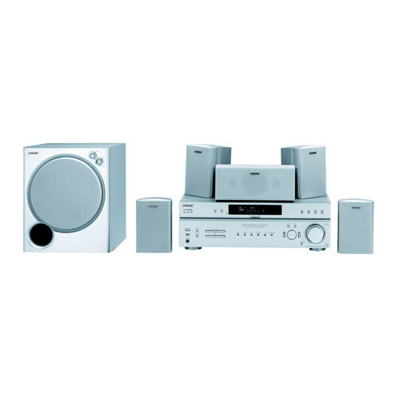
5 x 80 w receiver - satellite speaker combination with dolby digital, dolby pro logic ii and dts decoder.
Hide thumbs
Also See for HT-DDW760:
- Operating instructions manual (45 pages) ,
- Speakers connection (2 pages) ,
- Specifications (2 pages)

Related Manuals for Sony HT-DDW760


Summary of Contents for Sony HT-DDW760
- Page 1 4-252-086-13(1) Home Theatre System Operating Instructions HT-DDW760 ©2004 Sony Corporation...
- Page 2 TO PREVENT ELECTRIC SHOCK, MATCH WIDE BLADE OF PLUG TO WIDE SLOT, FULLY INSERT. Except for customers in Europe NERGY mark. As an E Sony Corporation has determined that this product meets the E ® guidelines for energy efficiency. ®...
-
Page 3: About This Manual
About This Manual • The instructions in this manual are for model HT-DDW760. Check your model number by looking at the lower right corner of the front panel. In this manual, HT-DDW760 models of area code CEL is used for illustration purposes unless stated otherwise. •... -
Page 4: Table Of Contents
Table of Contents Getting Started 1: Check how to hookup your components... 5 1a: Connecting components with digital audio output jacks ... 7 1b: Connecting components with multi channel output jacks... 9 (Models of area code CEL, CEK only) 1c: Connecting components with only analog audio jacks ... -
Page 5: 1: Check How To Hookup Your Components
Getting Started 1: Check how to hookup your components Steps 1a through 1c beginning on page 7 describe how to hook up your components to this receiver. Before you begin, refer to “Connectable components” below for the pages which describe how to connect each component. -
Page 6: Required Cords
Required cords The hookup diagrams on the subsequent pages assume the use of the following optional connection cords (A to F) (not supplied unless indicated). A Audio cord White (L) Red (R) B Audio/video cord Yellow (video) White (L/audio) Red (R/audio) C Video cord Yellow Notes... -
Page 7: 1A: Connecting Components With Digital Audio Output Jacks
1a: Connecting components with digital audio output jacks Hooking up a DVD player or satellite tuner For details on the required cords (A 1 Connect the audio jacks. OUTPUT DIGITAL COAXIAL DIGITAL OPTICAL VIDEO 2 DVD IN COAXIAL FRONT OUTPUT DIGITAL OPTICAL Note... -
Page 8: Dvd Player
2 Connect the video jacks. DIGITAL OPTICAL VIDEO 2 DVD IN COAXIAL FRONT MULTI CH IN Satellite tuner OUTPUT VIDEO ANTENNA VIDEO IN VIDEO IN CENTER AUDIO IN AUDIO IN SURROUND WOOFER MD/TAPE VIDEO 2 OUTPUT OUTPUT VIDEO DVD player TV monitor INPUT VIDEO... -
Page 9: 1B: Connecting Components With Multi Channel Output Jacks
1b: Connecting components with multi channel output jacks (Models of area code CEL, CEK only) 1 Connect the audio jacks. If your DVD player is equipped with multi channel output jacks, you can connect it to this receiver’s MULTI CH IN jacks to enjoy the multi channel sound. Alternatively, the multi channel input jacks can be used to connect an external multi channel decoder. - Page 10 2 Connect the video jacks. DIGITAL OPTICAL VIDEO 2 DVD IN COAXIAL FRONT MULTI CH IN DVD player OUTPUT VIDEO ANTENNA VIDEO IN VIDEO IN CENTER AUDIO IN AUDIO IN SURROUND WOOFER MD/TAPE VIDEO 2 TV monitor INPUT VIDEO MONITOR VIDEO OUT VIDEO IN VIDEO OUT...
-
Page 11: 1C: Connecting Components With Only Analog Audio Jacks
1c: Connecting components with only analog audio jacks Hooking up audio components For details on the required cords (A DIGITAL OPTICAL VIDEO 2 DVD IN COAXIAL CD player F), see page 6. – ANTENNA VIDEO IN VIDEO IN CENTER AUDIO IN AUDIO IN FRONT SURROUND... - Page 12 Hooking up video components If you connect your TV to the MONITOR VIDEO OUT jack, you can watch the video from the selected input (page 20). For details on the required cords (A DIGITAL OPTICAL VIDEO 2 DVD IN COAXIAL FRONT –...
-
Page 13: 2: Connecting The Antennas
2: Connecting the antennas Connect the supplied AM loop antenna and FM wire antenna. DIGITAL OPTICAL VIDEO 2 DVD IN COAXIAL FRONT SURROUND MULTI CH IN The shape of the connector varies depending on the area code. Notes • To prevent noise pickup, keep the AM loop antenna away from the receiver and other components. •... -
Page 14: 3: Connecting Speakers
3: Connecting speakers Connect your speakers to the receiver. This receiver allows you to use a 5.1 channel speaker system. To fully enjoy theater-like multi channel surround sound requires five speakers (two front speakers, a center speaker, and two surround speakers) and a sub woofer (5.1 channel). Example of 5.1 channel speaker system configuration Front speaker (Left) Sub woofer... - Page 15 Required cords A Speaker cords (supplied) (–) Surround speaker Surround speaker (Right) MONITOR VIDEO OUT AUDIO WOOFER INPUT Sub woofer B Monaural audio cord (supplied) Black Center speaker (Left) SURROUND CENTER FRONT SPEAKERS Front speaker (Right) Front speaker (Left)
-
Page 16: 4: Connecting The Ac Power Cord
4: Connecting the AC power cord Setting the voltage selector for the receiver and sub woofer If your receiver and sub woofer has a voltage selector on the rear panel, check that the voltage selector is set to the local power supply voltage. If not, use a screwdriver to set the selector to the correct position before connecting the AC power cord to a wall outlet. -
Page 17: 5: Setting Up The Speakers
Performing initial setup operations Before using the receiver for the first time, initialize the receiver by performing the following procedure. This procedure can also be used to return settings you have made to their factory defaults. Use the buttons on the receiver for the operation. Press ?/1 to turn off the receiver. - Page 18 DIST. X.X m (XX ft.) (Center speaker distance) Initial setting: 3.0 m (10 ft.) Lets you set the distance from your listening position to the center speaker. Center speaker distance should be set from a distance equal to the front speaker distance (A on page 17) to a distance 1.5 meters (5 feet) closer to your listening position (B on page 17).
-
Page 19: 6: Setting Up The Sub Woofer
6: Setting up the sub woofer Listening to the sub woofer POWER indicator Before playing the program source, set the volume to minimum on the receiver. Turn on the receiver. Press input buttons (e.g., DVD) to select the program source (e.g., DVD player). -
Page 20: Amplifier Operation
Amplifier Operation Selecting the component Press input buttons to select the input. To select the Satellite tuner DVD player MD or tape deck CD player Built-in tuner (FM/AM) TUNER FM/AM The selected input appears in the display. Turn on the component and start playback. -
Page 21: Listening To Fm/Am Radio
Listening to FM/AM radio You can listen to FM and AM broadcasts through the built-in tuner. Before operation, make sure you have connected the FM and AM antennas to the receiver (see page 13). The tuning scale differs depending on the area code as shown in the following table. -
Page 22: Storing Fm Stations Automatically
Storing FM stations automatically — AUTOBETICAL (Models of area code CEL, CEK only) This function lets you store up to 30 FM and FM RDS stations in alphabetical order without redundancy. Additionally, it only stores the stations with the clearest signals. If you want to store FM or AM stations one by one, see “Presetting radio stations”. -
Page 23: Using The Radio Data System (Rds)
Tuning to preset stations Press TUNER FM/AM repeatedly to select the FM or AM band. The last received station is tuned in. Press PRESET TUNING + or PRESET TUNING – repeatedly to select the preset station you want. Each time you press the button, you can select the preset station as follows: tA1yA2y...yA0yB1yB2y...yB0T tC0y...yC2yC1T... - Page 24 Notes • If there is an emergency announcement by government authorities, “ALARM” flashes in the display. • When the message consists of 9 characters or more, the message scrolls across the display. • If a station does not provide a particular RDS service, “NO XXXX”...
-
Page 25: Changing The Display
Changing the display Changing the information in the display You can check the sound field etc. by changing the information in the display. Press DISPLAY repeatedly. Each time you press DISPLAY, the display will change cyclically as follows. Index name of the input t Selected input t Sound field currently applied When the tuner is selected... -
Page 26: About The Indications In The Display
About the indications in the display L F E SP SLEEP OPT COAX SL S SR A SW: Lights up when the audio signal is output from the SUB WOOFER jack. B LFE: Lights up when the disc being played back contains the LFE (Low Frequency Effect) channel and the LFE channel signal is actually being reproduced. -
Page 27: Enjoying Surround Sound
Enjoying Surround Sound Using only the front speakers and sub woofer — 2CH STEREO In this mode, the receiver outputs the sound from the front left/right speakers and sub woofer only. When multi channel surround formats are input, the signals are downmixed to 2 channel with bass frequencies being output from the sub woofer. -
Page 28: Selecting A Sound Field
Sound fields with marks use DCS technology. DCS is the concept name of the surround technology for home theater developed by Sony. DCS uses the DSP (Digital Signal Processor) technology to reproduce the sound characteristics of an actual cinema cutting studio in Hollywood. -
Page 29: Selecting A Sound Field For Music
C.ST.EX C (CINEMA STUDIO EX C) Reproduces the sound characteristics of the Sony Pictures Entertainment scoring stage. This mode is ideal for watching musicals or films where orchestra music is featured in the soundtrack. About CINEMA STUDIO EX modes CINEMA STUDIO EX modes are suitable for watching motion picture DVDs (etc.), with... -
Page 30: Advanced Adjustments And Settings
Advanced Adjustments and Settings Switching the audio input mode for digital components — INPUT MODE You can switch the audio input mode for components which have digital audio input jacks. Press input buttons to select the input. Press INPUT MODE repeatedly to select the audio input mode. -
Page 31: Resetting Sound Fields To The Initial Settings
x CTR XXX dB (Center speaker level) x SUR.L. XXX dB (Surround speaker (left) level) x SUR.R. XXX dB (Surround speaker (right) level) x S.W. XXX dB (Sub woofer level) Initial setting: 0 dB You can adjust from –10 dB to +10 dB in 1 dB steps. COMP. -
Page 32: Adjusting The Tone
Adjusting the tone You can adjust the tonal quality (bass, treble level) of the front speaker using the TONE menu. Start playing a source encoded with multi channel surround effects (DVD, etc.). Press MAIN MENU repeatedly to select “ TONE ”. Press repeatedly to select the parameter you want to adjust. - Page 33 x DUAL XXX (Digital broadcast language selection) Lets you select the language you want to listen to during digital broadcast. This feature only functions for Dolby Digital sources. • M/S (Main/Sub) Sound of the main language will be output through the front left speaker and sound of the sub language will be output through the front right speaker simultaneously.
-
Page 34: Other Operations
Other Operations Naming preset stations and inputs You can enter a name of up to 8 characters for preset stations and inputs selected with input buttons, and display it in the receiver’s display. To index a preset station Press TUNER FM/AM repeatedly to select the FM or AM band, then tune in the preset station you want to create an index name for (page 23). -
Page 35: Using The Sleep Timer
Using the Sleep Timer You can set the receiver to turn off automatically at a specified time. Use the remote for the operation. Press ALT to light up the button. Press SLEEP while the power is on. Each time you press SLEEP, the display changes cyclically as follows: 2-00-00 t 1-30-00 t 1-00-00 t 0-30-00 t OFF... - Page 36 Recording on a video tape You can record from a VCR, a TV or a DVD using the receiver. You can also add audio from a variety of audio sources when editing a video tape. See the operating instructions of your VCR or DVD player if you need help.
-
Page 37: Operations Using The Remote Rm-Pp760
Operations Using the Remote RM-PP760 You can use the remote RM-PP760 to operate the components in your system. Before you use your remote Inserting batteries into the remote Insert R6 (size-AA) batteries with the + and – properly oriented in the battery compartment. When using the remote, point it at the remote sensor on the receiver. - Page 38 Remote Operations Button ALT wd Remote ANGLE 7 DVD player ANT 9 AUDIO 7 TV/VCR/ DVD player AV MENU VCR/ Satellite tuner/ DVD player AV1 4 and Remote AV2 3 AV ?/1 wl TV/VCR/ CD player/ VCD player/ LD player/ DVD player/ MD deck/ DAT deck...
- Page 39 SUBTITLE DVD player Changes the subtitles. SYSTEM Receiver/TV/ Turns off the receiver STANDBY VCR/Satellite and other Sony audio/ (Press AV tuner/ video components. ?/1 wl and CD player/ ?/1 e; at VCD player/ the same LD player/...
-
Page 40: Selecting The Command Mode Of The Remote
Remote Operations Button H q; VCR/ CD player/ VCD player/ LD player/ DVD player/ MD deck/ DAT deck/ Tape deck X qa VCR/ CD player/ VCD player/ LD player/ DVD player/ MD deck/ DAT deck/ Tape deck x wa VCR/ CD player/ VCD player/ LD player/... -
Page 41: Programming The Remote
Furthermore, you can also program the remote for Sony components that the remote is unable to control. Note that the remote can only control components that accept infrared wireless control signals. - Page 42 Use the numeric codes in the tables below to control non-Sony components and also Sony components that the remote is normally unable to control. Since the remote signal that a...
- Page 43 TELEFUNKEN 751, 752 TOSHIBA 747, 755, 756 ZENITH * If an AIWA VCR does not work even though you enter the code for AIWA, enter the code for Sony instead. To control a DVD player Maker Code(s) SONY 401, 402, 403...
-
Page 44: Additional Information
Do not use any type of abrasive pad, scouring powder or solvent such as alcohol or benzine. If you have any question or problem concerning your receiver, please consult your nearest Sony dealer. -
Page 45: Troubleshooting
Troubleshooting If you experience any of the following difficulties while using the receiver, use this troubleshooting guide to help you remedy the problem. There is no sound or only a very low-level sound no matter which component is selected. • Check that the speakers and components are connected securely and correctly. -
Page 46: Remote Control
MENU after pressing the input button. Irregular current is output from the speakers. The receiver will automatically turn off after a few seconds. Check the speaker connection and turn on the power again. If this problem persists, consult your nearest Sony dealer. on the... -
Page 47: Specifications
If the problem persist Consult your nearest Sony dealer. Reference sections for clearing the receiver’s memory To clear All memorized settings... - Page 48 1) Measured under the following conditions: Area code SP, CEL, CEK AU, E51 2) Depending on the sound field settings and the source, there may be no sound output. Inputs (Analog) MULTI CH IN*, CD, Sensitivity: 800 mV MD/TAPE, VIDEO 1, 2, Impedance: 50 kiloohms Inputs (Digital) DVD (Coaxial)
- Page 49 Speaker section Front speakers (SS-MSP760L/ SS-MSP760R) Center speaker (SS-CNP760) Surround speakers (SS-MSP760SL/ SS-MSP760SR) Front/center speakers Full range, magnetically shielded Surround speakers Full range Speaker units 80 mm cone type Enclosure type Bass reflex Rated Impedance 6 ohms Dimension (w/h/d) (Approx.) Front/surround speakers 102 ×...
-
Page 50: List Of Button Locations And Reference Pages
List of button locations and reference pages How to use pages 50 and 51 Use this page to find the location of buttons that are mentioned in the text. Main unit ALPHABETICAL ORDER A - L A.F.D. (button/indicator) 9 (27, 28, 29, 45) CD wg (20) DIMMER 3 (25) - Page 51 9 q; qa qfqd...
-
Page 52: Index
Indexing. See Naming Labeling. See Naming LEVEL menu 30 Naming 34 Preset stations how to 22 how to tune 23 Sony Corporation Printed in Malaysia RDS 23 Recording on a video tape 36 on an audio tape or MD 35 Selecting component 20 –...