Table of Contents
Advertisement
Quick Links
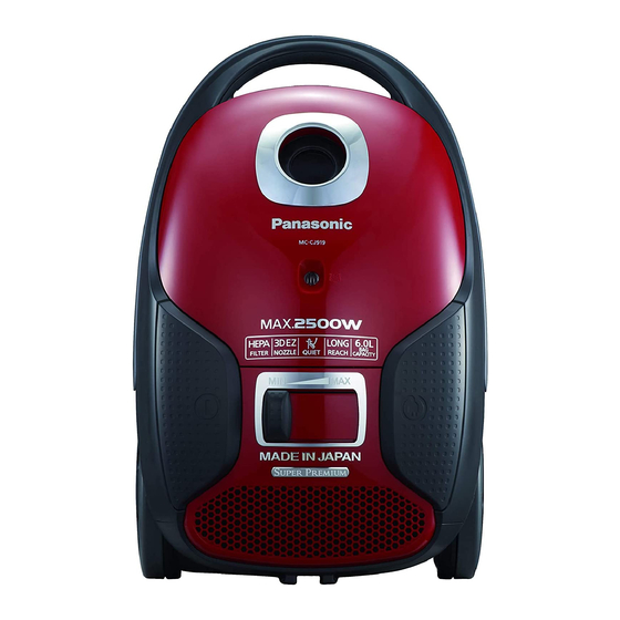
MC-CJ919-R249
Model No.
MC-CJ917-K249
Model No.
MC-CJ917-W249
Model No.
MC-CJ915-R249
Model No.
MC-CJ915-W249
Model No.
MC-CJ913-K249
Model No.
MC-CJ913-Y249
Model No.
MC-CJ911-R249
Model No.
Product Color : (R) Red (K) Black (W) White (Y) Yellow
Destination :
Iran
© Panasonic Corporation 2017 Unauthorized copy-
ing and distribution is a violation of law.
Order Number VCB1702003CE
Vacuum Cleaner
Advertisement
Table of Contents

Related Manuals for Panasonic MC-CJ919-R249


Summary of Contents for Panasonic MC-CJ919-R249
- Page 1 MC-CJ915-W249 Model No. MC-CJ913-K249 Model No. MC-CJ913-Y249 Model No. MC-CJ911-R249 Model No. Product Color : (R) Red (K) Black (W) White (Y) Yellow Destination : Iran © Panasonic Corporation 2017 Unauthorized copy- ing and distribution is a violation of law.
-
Page 2: Table Of Contents
TABLE OF CONTENTS PAGE PAGE 1 Specifications ------------------------------------------------------3 2 Location of Controls and Components--------------------4 3 Troubleshooting Guide------------------------------------------5 4 Disassembly and Assembly Instructions -----------------8 4.1. Disassembly of the Dust Cover Assy -----------------8 4.2. Disassembly of the Dust Bag Holder------------------9 4.3. Disassembly of Body Cover Assy, Switch Pedal, Cord Rewind Button---------------------------- 10 4.4. -
Page 3: Specifications
1 Specifications Model No. MC-CJ919 MC-CJ917 MC-CJ915 MC-CJ913 MC-CJ911 Power source 220V -240V 50/60 Hz Max. input 2500 W 2300 W 2100 W 2000 W 1900 W Nominal input 1700 -2100 W 1600 -2000 W 1550 -1900 W 1500 -1800 W 1450 -1700 W Dimensions (W x L x H) 320 mm x 500 mm x 265 mm... -
Page 4: Location Of Controls And Components
2 Location of Controls and Components... -
Page 5: Troubleshooting Guide
3 Troubleshooting Guide CONDITION CHECKPOINT FIGURE CHECK METHOD REMEDY The Motor CORD REEL • Check the continuity at both • If there is no continuity, replace doesn’t rotate. UNIT ends of the Plug and both ends the Cord Reel Unit, or the Rail RAIL BASE of the Lead Wire Terminal of Base Unit. - Page 6 CONDITION CHECKPOINT FIGURE CHECK METHOD REMEDY TRIAC (on the • Check the Triac by conducting • If there is a problem, replace P.C.B. Assy) the following inspection. the P.C.B. Assy. ON/OFF • Check the continuity by press- • If there is a problem, replace SWITCH ing the On/Off Switch.
- Page 7 CONDITION CHECKPOINT FIGURE CHECK METHOD REMEDY 1. The suction DUST BAG MC-CJ919/ MC-CJ917/ MC-CJ915/ Check for clogging with dust. Remove dust. power is low. FILTER MC-CJ913 • Dust Bag • Replace any broken Dust Bag, 2. The Motor EXTENSION • Filter (in the Dust Box) Filter, and/or Hose Unit.
-
Page 8: Disassembly And Assembly Instructions
4 Disassembly and Assembly Instructions Important: Always turn the vacuum cleaner is power off before replacing components. Remove the power cord and plug from the mains. * Attention (1) When disassembling the vacuum cleaner, check the connections and wiring (pulling) of each component, and ensure that everything is restored correctly once repairs are complete. -
Page 9: Disassembly Of The Dust Bag Holder
Disassembly of the Dust Bag 4.2. Holder 1. Remove the Dust Bag Holder by inserting a slotted screwdriver into the mount of the Dust Bag Holder on the Lower Body Unit. Caution (There is a Spring inside) * When replacing the Dust Bag Holder, disassemble and replace the Spring mounted inside. -
Page 10: Disassembly Of Body Cover Assy, Switch Pedal, Cord Rewind Button
4.3. Disassembly of Body Cover Assy, Switch Pedal, Cord Rewind Button 1. Remove the Filter Case 2. Remove 3 screws and disassemble the Body Cover Assy... -
Page 11: Disassembly Of Upper Body, Handle Cover, And Guide Lever
4.4. Disassembly of Upper Body, 3. Disassemble the Switch Pedal/Cord Rewind Button toward the direction of the arrow Handle Cover, and Guide Lever Caution: (Spring is placed inside.) *Be careful not to lose the Spring. 1. Disassemble the Body Cover Assy and Switch Pedal as described in (4.3). - Page 12 3. Slide the Switch, and push it inward at the position 5. Disassembly of Handle Cover shown in the figure. Disassemble the Handle Cover from the Upper Body. 6. Disassembly of Guide Lever Slide and disassemble the Guide Lever to the direc- tion of the arrow.
-
Page 13: Disassembly Of Motor Case Set
4.5. Disassembly of Motor Case Set 4.6. Disassembly of Cord Reel Unit 1. Disassemble the Rear Cover to the direction of the 1. Release the pretension of the Cord Reel Unit slowly arrow, and disassemble the Motor Case Set pulling by holding on the Power Plug and pressing on the upward. -
Page 14: Disassembly Of Rail Base Unit
4.7. Disassembly of Fan Motor Unit Disassembly of Rail Base Unit 4.8. 1. Remove screw and disassemble the Rail Base Unit from 1. Disassemble the Swivel Cap and remove 3 screws. the Motor Case Set. 2. Remove the faston terminals on the Rail Base Unit. 2. - Page 15 3. Disassemble the Noise Suppressor Unit 5. Remove 2 screws and disassemble the Motor Support 4. Disassemble the Motor Support Rubber (Rear) Front 6. Remove the Motor Support Rubber (Front)
-
Page 16: Disassembly Of P.c.b. Assy
4.9. Disassembly of P.C.B. Assy 1. Disassembly of Volume (a part of P.C.B. Assy) Disassemble the Volume by widening the tab of the Motor Case Unit using a slotted screwdriver. 2. Disassemble the P.C.B. Holder by pressing on the 3. Remove the faston terminals and disassemble the P.C.B. -
Page 17: Replacement Of Blower Cover
4.10. Replacement of Blower Cover 1. Assemble the Spring (for Blower Cover) onto the Blower Cover 2. Assemble by inserting the shaft of the Blower Cover into the boss hole. -
Page 18: Wiring Connection Diagram
5 Wiring Connection Diagram... -
Page 19: Exploded View And Replacement Parts List
6 Exploded View and Replacement Parts List 6.1. MC-CJ919/ MC-CJ917 6.1.1. EXPLODED VIEW (ATTACHMENTS) 6.1.2. PARTS LIST (ATTACHMENTS) Safety Ref. No. Part No. Part Name & Description Pcs/Set Remarks AMV84PB80S0J HOSE UNIT (HOSE) MC-CJ919/ MC-CJ917 AMC24P-0R0V HOSE SUPPORTER AMV92PB80V0J CONNECTION PIPE AMV98PB80V0J CURVED WAND (SUCTION REGULATOR) -
Page 20: Mc-Cj915
6.2. MC-CJ915 6.2.1. EXPLODED VIEW (ATTACHMENTS) 6.2.2. PARTS LIST (ATTACHMENTS) Safety Ref. No. Part No. Part Name & Description Pcs/Set Remarks AMV75PB60V0J HOSE C UNIT (HOSE) MC-CJ915/ MC-CJ913/ MC-CJ911 AMC24P-0R0V HOSE SUPPORTER AMV92PB80V0J CONNECTION PIPE AMV98PB80V0J CURVED WAND (SUCTION REGULATOR) AMV99P9U000J EXTENSION WAND ASSY (TELESCOPIC WAND) -
Page 21: Mc-Cj913
6.3. MC-CJ913 6.3.1. EXPLODED VIEW (ATTACHMENTS) 6.3.2. PARTS LIST (ATTACHMENTS) Safety Ref. No. Part No. Part Name & Description Pcs/Set Remarks AMV75PB60V0J HOSE C UNIT (HOSE) MC-CJ915/ MC-CJ913/ MC-CJ911 AMC24P-0R0V HOSE SUPPORTER AMV92PB80V0J CONNECTION PIPE AMV98PB80V0J CURVED WAND (SUCTION REGULATOR) AMC99P-HP0 EXTENSION WAND ASSY (TELESCOPIC WAND) -
Page 22: Mc-Cj911
6.4. MC-CJ911 6.4.1. EXPLODED VIEW (ATTACHMENTS) 6.4.2. PARTS LIST (ATTACHMENTS) Safety Ref. No. Part No. Part Name & Description Pcs/Set Remarks AMV75PB60V0J HOSE C UNIT (HOSE) MC-CJ915/ MC-CJ913/ MC-CJ911 AMC24P-0R0V HOSE SUPPORTER AMV92PB80V0J CONNECTION PIPE AMV98PB80V0J CURVED WAND (SUCTION REGULATOR) AMC40P-QN0 EXTENSION WAND MC-CJ911... -
Page 23: Exploded View (Body)
6.5. EXPLODED VIEW (BODY) -
Page 24: Parts List (Body)
DUST COVER ASSY MC-CJ915-R249 AMV93KB60WBJ DUST COVER ASSY MC-CJ915-W249 AMV93KB70KBJ DUST COVER ASSY MC-CJ917-K249 AMV93KB70WBJ DUST COVER ASSY MC-CJ917-W249 AMV93KB80RBJ DUST COVER ASSY MC-CJ919-R249 XTN4+20BFJ SCREW AMV0YAB40R0J BODY COVER ASSY MC-CJ911-R249 AMV0YAB50K0J BODY COVER ASSY MC-CJ913-K249 AMV0YAB50Y0J BODY COVER ASSY MC-CJ913-Y249 AMV0YAB60R0J... - Page 25 Safety Ref. No. Part No. Part Name & Description Pcs/Set Remarks AMV46ZB8000J PARTITION BOARD AMV01ZB8000J INSTRUCTION BOOK AMV61ZB4000J INDIVIDUAL CARTON MC-CJ911 AMV61ZB5000J INDIVIDUAL CARTON MC-CJ913 AMV61ZB6000J INDIVIDUAL CARTON MC-CJ915 AMV61ZB7000J INDIVIDUAL CARTON MC-CJ917 AMV61ZB8000J INDIVIDUAL CARTON MC-CJ919 AMV10ZB8000J BODY BAG...